Table of Contents
Advertisement
Quick Links
Advertisement
Table of Contents

Related Manuals for OPTI-UPS DS-D33


Summary of Contents for OPTI-UPS DS-D33
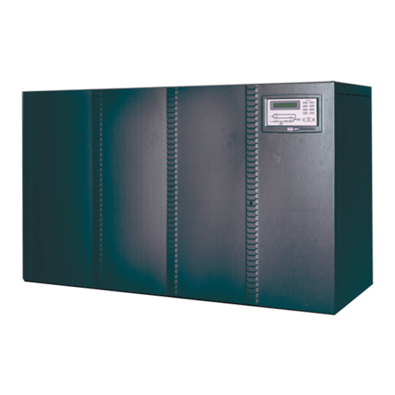
- Page 1 OPTI-UPS User’s Guide Durable Series Models DS-D33 www.opti-ups.com...
-
Page 2: Table Of Contents
Contents Page 1. SYSTEM OVERVIEW ................1-1 1.1. Construction of the UPS ..............1-1 1.2. Features and Advantages..............1-5 1.3. Rectifier ....................1-8 1.4. Inverter ....................1-9 1.5. Static Switch ..................1-10 1.6. Maintenance Bypass Switch .............. 1-11 1.7. Dimension & Drawings ..............1-12 1.8. - Page 3 Contents Page 5.5. Menu 4 – Historical Event Menu ............5-5 5.6. Menu 5 – Parameter Setting Menu............5-6 5.7. Menu 6 – Rectifier Data Menu ............5-7 5.8. Menu 7 – Output Data Menu ............... 5-8 5.9. Menu 8 – Other Data Menu ..............5-8 5.10.
- Page 4 CAUTION ! ☆ Hazardous voltage exits inside the UPS (includes the connection terminals), cable connection and maintenance should be done by professional or qualified personnel. ☆ The UPS has its own internal battery source (battery). The output terminals may be live even when the UPS is not connected to the AC supply.
-
Page 5: System Overview
SYSTEM OVERVIEW 1.1. Construction of the UPS General Topology: The UPS system is composed of input breakers, input filter & protection network, rectifier, battery bank, inverter, static switch, bypass breaker, isolation transformer and output filter. The basic topology is shown in the diagram above. Under normal AC mode, energy from the AC source is converted to DC power and supply to the inverter and charge the battery to its full capacity all the time, ready to support the output load in case of AC source failure. - Page 6 Besides, the knowledge of choosing the best and most suitable UPS can be easy or can be difficult, it depends on whether you know the key points or not. The most obvious specification is the power, it depends on how large is your load. Usually, an allowance of 50% more power must be added to the current power you needed, both for tolerance and future expansion.
- Page 7 Back-up Mode: Since the battery is connected directly to the DC bus, when the AC failure, the battery change immediately from receiver to donor, supply energy to the inverter instead of receiving energy from the rectifier. The output AC is not interrupted. Therefore, the load connected to the output is protected.
- Page 8 Maintenance Bypass Mode: In case of UPS maintenance or battery replacement, and the load cannot be interrupted, the user can turn off the inverter, close the bypass breaker and then open the rectifier and reserve breakers. The AC output will not be interrupted during manual bypass transfer procedure.
-
Page 9: Features And Advantages
1.2. Features and Advantages (a) Reliable input protection: Circuit breakers is put in each individual input loop to ensure power can continue through the other loop in case of breaker trip caused abnormal condition in either rectifier or load. (b) Input surge protection: MOV (surge protector) is added at the input, provide sufficient protection to both UPS and the load from any lightning or surge caused by neighboring large loads. - Page 10 (g) P&P Modular design: The power circuit is separated into several modules plugged into slots in the UPS, which is easy to pull out, permit quick maintenance and easier trouble shooting. Therefore, it can be regarded as plug and play modules. (h) Cold start function: the UPS can be started without AC source, that is, can be started with battery only, because current limit circuitry is added.
- Page 11 (n) Intelligent battery test: Battery is tested after every boost charge of battery (either initiated by battery discharge or by one month has elapsed) without stopping the rectifier to prevent the risk of output AC failure in case of battery bad.
-
Page 12: Rectifier
1.3. Rectifier The main function of a rectifier is to convert the AC input to DC power, supply it to the inverter; the inverter then converts the DC power to AC power to the load. Our UPS use the DC power to charge the battery as well, which is the most efficient way of charging. -
Page 13: Inverter
PH ASE SH IFT TRANSFO RMER RECTIFIER O UTPUT BREAK ER INDUCTO R INPUT CAPACITO R 12-PULSE FULL CONTROL RECTIFIER In order to further improve the power factor and reduce harmonic current drawn by the rectifier, our UPS from 100KVA and above use the 12-pulse full controlled rectifier. -
Page 14: Static Switch
The inverter is composed of IGBT, inductor, capacitor, snubber, control circuitry and protection circuitry. It can convert the DC power from the DC bus to AC power supply to the output load. Our UPS use IGBT technology which can switched to frequency beyond audible range, therefore no audible noise. -
Page 15: Maintenance Bypass Switch
The static switch is composed of two pairs of back-to-back connected SCR. It can transfer the load from reserve to inverter or from inverter to reserve without dead time at the output. Therefore, it is a very important portion of a UPS. Detection circuitry is added to the control circuit to achieve zero dead time transfer. -
Page 16: Dimension & Drawings
1.7. Dimension & Drawings 20KVA ~ 60KVA OUTLINE DRAWING 1-12... - Page 17 20KVA ~ 60KVA INTERIOR DRAWING 1-13...
- Page 18 80KVA ~ 160KVA OUTLINE DRAWING 1-14...
- Page 19 80KVA ~ 160KVA INTERIOR DRAWING 1-15...
- Page 20 200KVA ~ 320KVA OUTLINE DRAWING 1-16...
- Page 21 200KVA ~ 320KVA INTERIOR DRAWING 1-17...
- Page 22 INTER-PCB DIAGRAM 1-18...
- Page 23 WARN ING INVE RTE R ON RESERVE AC FAIL RECT AC FAIL HIGH DC INVE RTER SS RESERVE FREQ F AIL SHORT CIRCUIT BATTERY LO W RESE RVE FAIL BAT LOW BATTERY LO W FUSE/OVE R TEMP SD SHUTDO WN INVE RTER FAIL RECT AC F AIL SHUTDO WN...
-
Page 24: Front Panel
The front panel is located at the front of the PCB holder. It gathers the real time information of the UPS and shows them clearly to the user. It also provides switches for controlling and setting the UPS. So, through this panel, the UPS can be not only a stand alone machine supplying the load but closely related to the user. - Page 25 RESERVE AC FAIL – reserve AC magnitude is out of range. RESERVE FREQ FAIL – reserve frequency is out of range. BATTERY LOW – DC bus (or battery) is lower than 320VDC, low battery shutdown is approaching. BATTERY LOW SHUTDOWN – inverter shutdown due to DC bus (or battery) is lower than 295VDC (lower than the acceptable DC voltage of the inverter.
- Page 26 BAT LOW – the LED will lit as long as the DC voltage is lower than 320VDC. BAT LOW STOP – the LED will lit as long as the DC voltage is lower than 295VDC, inverter on is prohibited. FAULT – the inverter is shutdown due to abnormal conditions such as overload, short circuit, high DC, fuse over temperature, bypass breaker on or emergent stop.
- Page 27 EMERGENT STOP - beep continuously The buzzer will also beep once every time the inverter is switched on or off to acknowledge the user his key is valid and accepted. E. Bypass LED: This LED will lit when the maintenance bypass breaker is closed. When the maintenance bypass breaker is closed, the inverter cannot be switched on and will stop immediately even when inverter is already running.
- Page 28 M. Up key: This is a LCD control key. It is for moving the cursor one item upward when items are being selected or for changing the number/character forward when data or parameter of the UPS is being set. N. Down key: This is a LCD control key. It is for moving the cursor one item downward when items are being selected or for changing the number/ character backward when data or parameter of the UPS is being set.
-
Page 29: Technical Specification
TECHNICAL SPECIFICATION 2.1. 20KVA ~ 60KVA UPS 3-Phase Input / 3-Phase Output TECHNICAL SPECIFICATION RECTIFIER 220V∆ / 380V∆ / 460V∆, 208VY / INPUT VOLTAGE 380VY / 400VY / 415VY INPUT RANGE 307 – 520V INPUT FREQUENCY 50 / 60 Hz +/- 7% INPUT POWER FACTOR NORMAL INPUT CURRENT(A) MAXIMUM INPUT CURRENT(A) - Page 30 INVERTER DC INPUT RANGE 285 – 415VDC WAVE FORM SINUSOID 208 / 380 / 400 / 415 VY 3 PHASE OUTPUT VOLTAGE WITH NEUTRAL OUTPUT POWER FACTOR VOLTAGE REGULATION 100% + / - 1 % UNBALANCE LOAD FREQUENCY LOCK RANGE 45 –...
- Page 31 OVERALL CHARACTERISTICS OVERALL EFFICIENCY 91.5% OPERATING ENVIRONMENT: 0 – 40℃ ( 32 – 104℉ ) - TEMPERATURE - HUMIDITY 0% - 90% ( NON–CONDENSING ) - ALTITUDE <1500 M ABOVE SEA LEVEL MAXIMUM HEAT DISSIPATION(KW) WEIGHT(Kg) DIMENSION: - HEIGHT(mm) 1600 - WIDTH(mm) - DEPTH(mm) - AUDIBLE NOISE...
-
Page 32: 80Kva ~ 160Kva Ups 3-Phase Input / 3-Phase Output
2.2. 80KVA ~ 160KVA UPS 3-Phase Input / 3-Phase Output TECHNICAL SPECIFICATION RECTIFIER 220V∆ / 380V∆ / 460V∆, 208VY / INPUT VOLTAGE 380VY / 400VY / 415VY INPUT RANGE 307 – 520V INPUT FREQUENCY 50 / 60 Hz +/- 7% INPUT POWER FACTOR NORMAL INPUT CURRENT(A) MAXIMUM INPUT CURRENT(A) - Page 33 INVERTER DC INPUT RANGE 285 – 415VDC WAVE FORM SINUSOID 208 / 380 / 400 / 415 VY 3 PHASE OUTPUT VOLTAGE WITH NEUTRAL OUTPUT POWER FACTOR VOLTAGE REGULATION + / - 1 % 100% UNBALANCE LOAD FREQUENCY LOCK RANGE 45 –...
- Page 34 OVERALL CHARACTERISTICS 92.5% OVERALL EFFICIENCY 92.5% OPERATING ENVIRONMENT: 0 - 40℃ ( 32 - 104℉ ) - TEMPERATURE - HUMIDITY 0% - 90% ( NON–CONDENSING ) - ALTITUDE <1500 M ABOVE SEA LEVEL MAXIMUM HEAT DISSIPATION(KW) WEIGHT(Kg) 1180 1450 DIMENSION: - HEIGHT(mm) 1600 - WIDTH(mm)
-
Page 35: 20Kva ~ 50Kva Ups 3-Phase Input / 1-Phase Output
2.3. 20KVA ~ 50KVA UPS 3–Phase Input / 1-Phase Output TECHNICAL SPECIFICATION RECTIFIER 220V∆ / 380V∆ / 460V∆, 208VY / INPUT VOLTAGE 380VY / 400VY / 415VY INPUT RANGE 307 – 520V INPUT FREQUENCY 50 / 60 Hz +/- 7% INPUT POWER FACTOR NORMAL INPUT CURRENT(A) MAXIMUM INPUT CURRENT(A) - Page 36 INVERTER DC INPUT RANGE 285 – 415VDC WAVE FORM SINUSOID OUTPUT VOLTAGE 220 / 230 / 240 V, 1p2w or 1p3w OUTPUT POWER FACTOR VOLTAGE REGULATION + / - 1 % 0-100% LOAD FREQUENCY LOCK RANGE 45 – 55 Hz / 55 – 65 Hz OUTPUT FREQUENCY 50 / 60 Hz + / - 0.1 Hz (FREE RUNNING)
- Page 37 OVERALL CHARACTERISTICS OVERALL EFFICIENCY 91.5% OPERATING ENVIRONMENT: 0 - 40℃ ( 32 - 104℉ ) - TEMPERATURE - HUMIDITY 0% - 90% ( NON–CONDENSING ) - ALTITUDE <1500 M ABOVE SEA LEVEL MAXIMUM HEAT DISSIPATION(KW) WEIGHT(Kg) DIMENSION: - HEIGHT(mm) 1600 - WIDTH(mm) - DEPTH(mm) - AUDIBLE NOISE...
- Page 38 2.4. 200KVA ~ 320KVA UPS 3-Phase Input / 3-Phase Output TECHNICAL SPECIFICATION RECTIFIER 220V∆ / 380V∆ / 460V∆, 208VY / 380VY INPUT VOLTAGE / 400VY / 415VY INPUT RANGE 307 – 520V INPUT FREQUENCY 50 / 60 Hz +/- 7% INPUT POWER FACTOR NORMAL INPUT CURRENT(A) MAXIMUM INPUT CURRENT(A)
- Page 39 INVERTER DC INPUT RANGE 285 – 415VDC WAVE FORM SINUSOID 380 / 400 / 415 V 3 PHASE WITH OUTPUT VOLTAGE NEUTRAL OUTPUT POWER FACTOR VOLTAGE REGULATION + / - 1 % 0-100% LOAD FREQUENCY LOCK RANGE 45 – 55 Hz / 55 – 65 Hz OUTPUT FREQUENCY 50 / 60 Hz + / - 0.1 Hz (FREE RUNNING)
- Page 40 OVERALL CHARACTERISTICS OVERALL EFFICIENCY OPERATING ENVIRONMENT: 0 - 40℃ ( 32 - 104℉ ) - TEMPERATURE - HUMIDITY 0% - 90% ( NON–CONDENSING ) - ALTITUDE <1500 M ABOVE SEA LEVEL MAXIMUM HEAT 11.5 16.3 17.4 DISSIPATION(KW) WEIGHT(Kg) 2500 2700 3000 3100 DIMENSION:...
-
Page 41: Installation
3. INSTALLATION 3.1. Site & Environment Consideration The main function of the UPS is to provide an safe, clean independent electrical supply to the load so that it is free from any random variations, disturbances or interruptions of the utility Mains, provide a constant power supply which is perfectly regulated in both voltage and frequency. - Page 42 (e) It is necessary to guarantee the temperature and humidity values of the site into which the UPS will be installed should be within the range allowed by the specification. The UPS is capable of continuous normal operation within a temperature range of 0℃(32℉) to 40℃(104℉).
- Page 43 (h) Walls, ceilings, floors or anything near to the UPS should be preferably constructed of non-combustible materials. The portable fire extinguisher should be accessible nearby in case of hazard. (i) Avoid accumulating litter or trash of any sort in or around the UPS system. The floor area surrounding the UPS should be kept clean so that metallic powder and filings are not sucked into the unit thus causing a short circuit and damage to the system.
-
Page 44: Unpacking
3.2. Unpacking Carefully take off all the packaging material of the UPS, then carefully locate the UPS onto site which has selected with all the points in section 3.1 kept in mind. The UPS had past the production testing and QC checking all the electrical and mechanical characteristics in detail prior to shipment from the factory, therefore the UPS should be in proper conditions upon receipt. -
Page 45: Cable Selection
3.3. Cable Selection The following tables list all the information between KVA of the UPS and the size and rating of the cables. Inadequate cable size or over sized breaker will incur risk of fire or damage of insulation. Therefore, please look up the following tables to determine the input circuit breaker rating and the size of cable for input, output and battery connections. - Page 46 230/400V 3Φ 230/400V 3Φ 230/400V 3Φ 230/400V 3Φ 60*2 80*2 230/400V 3Φ 100*2 125*2 230/400V 3Φ 150*2 200*2 CABLE SIZE FOR OUTPUT OUTPUT In(A) R/S/T(mm N(mm 230/400V 3Φ 230/400V 3Φ 230/400V 3Φ 230/400V 3Φ 230/400V 3Φ 230/400V 3Φ 230/400V 3Φ 230/400V 3Φ...
- Page 47 FUSE RATING & CABLE SIZE FOR BATTERY ☆ THE BATTERY VOLTAGE IS 295 – 410V Imax(A) FUSE(A) CABLE(mm 125*2 38*2 160*2 50*2 200*2 80*2 200*2 80*2 200*4 80*4 200*4 80*4...
-
Page 48: Terminal Connection
3.4. Terminal Connection Although different KVA of the UPS may have different cable connection terminal, all our standard UPS connection terminal alignment falls into one of the following types: RESERVE RECTIFIER BATTERY INPUT INPUT OUTPUT INPUT 3 PHASE INPUT / 3 PHASE OUTPUT TERMINAL WITH TWO SOURCE RECTIFIER &... - Page 49 For single phase output UPS, the current is very much larger in single phase terminal, therefore the terminal looks bigger than it is needed. RESERVE RECTIFIER BATTERY INPUT INPUT OUTPUT INPUT 3 PHASE INPUT / 1 PHASE OUTPUT TERMINAL WITH TWO SOURCE RECTIFIER &...
-
Page 50: Operations
OPERATIONS After all cables have been connected, the UPS is ready to operate once power source is available at the input terminal. Before turn on any switch or breaker, check once again the following points listed below: (a) Check the input voltage if it conforms with the UPS’s rated input voltage. -
Page 51: Shutdown Procedure
~ ~ ~ ~ ~ ~ ~ MIMIC DISPLAY UNDER NORMAL OPERATION (d) Push inverter on switch – To on the inverter, the inverter on switch and the control switch must be pressed simultaneously. The inverter will start working and inverter output will be established in 4 sec. The load will be automatically transferred to the inverter 3 sec. -
Page 52: From Inverter To Bypass Procedure
(b) Open the battery breaker – If you want to shutdown all the power of the UPS, continue to open the battery breaker. Now the DC bus is only supported by the rectifier. (c) Open the rectifier breaker – Open the rectifier breaker will then further take the power source away from the DC bus;... -
Page 53: From Bypass To Inverter Procedure
(b) Open the battery breaker – You have to shutdown the power inside the UPS; therefore, continue to open the battery breaker. (c) Open the rectifier breaker – Open the rectifier breaker will then further take the power source away from the DC bus; therefore, the DC bus will start to drop slowly. - Page 54 (c) Close the rectifier breaker - The rectifier will be automatically started if the power source connected is correct. The DC voltage will slowly rise up (15 – 30sec.) until the designated voltage is reached, and will keep the value anyhow. Now, the DC is already ready for the inverter.
-
Page 55: Lcd Display
LCD DISPLAY The LCD can display information much more than LED can do. In order to make the display sharp and readable, the LCD is back-lighted by LEDs. But since we want to further prolong the life time of the LED, the CPU will cut off the power of the LED 3 minutes after the last key of either UP, DOWN or ENTER is pressed. -
Page 56: Menu 1 - Select Menu
Serial number is set by factory for the convenience of maintenance personnel who may need to take down the serial no. of the UPS he has attended. The identification no. is set only when external module connect to more than one UPS, each UPS must have a unique number to identify itself, and it should be set by installation technical personnel after installation. -
Page 57: Menu 2 - Status / Warning Menu
The number can be changed upward or downward by the UP( ↑ ) or the DOWN(↓) key, and can be confirmed by the ENTER(←┘) key. The password is a 4 digit number. The selection will continue if correct password is entered, or will go back to MENU 0 the MAIN MENU if no correct password is entered after 3 trials. -
Page 58: Menu 3 - Real Time Data Menu
The inverter should be shut off under short circuit. Since the CPU detect it is short circuit, in order to avoid unnecessary tripping and hurting of the breaker, the static switch remains in conducting the inverter (will not transfer to reserve). List below are all the warning conditions that can be displayed (they are arranged in order of priority, start with the highest priority): 1st row : BYPASS ON / RECT AC FAIL / RECTIFIER PHASE ERROR /... -
Page 59: Menu 4 - Historical Event Menu
It is a select menu jump from MENU 1 when the REAL TIME DATA is selected. The cursor (→) is used to select what type of real time data the user what to view, such as RECTIFIER DATA, RESERVE DATA, OUTPUT DATA, OTHER DATA etc. -
Page 60: Menu 5 - Parameter Setting Menu
The abnormal conditions can be displayed are listed below: HIGH DC SHUTDOWN / SHORT CIRCUIT! / FUSE/OVERHEAT / OVERLOAD SHUTDOWN / EMERGENT STOP / INVERTER ABNORMAL / BYPASS ON SHUTDOWN Besides, on the top right corner the screen, the UPS run time is displayed in year/month for the reference of the user or maintenance personnel to estimate the time for maintenance. -
Page 61: Menu 6 - Rectifier Data Menu
The second item can be set is the BUZZER ON/OFF, when it is selected ‘BUZZER ON/OFF’ will be displayed, where the ‘ON’ will blink if the buzzer status is on, and the ‘OFF’ will blink if the buzzer status is off. The intended status can be changed by UP ( ↑... -
Page 62: Menu 7 - Output Data Menu
5.8. Menu 7 – Output Data Menu < > O U T P U T D A T A O U T P U T F R E Q U E N C Y = X X L O A D : R = X X X S = X X X T = X X X R - N = X X X... -
Page 63: Menu 9 - Reserve Data Menu
< > O T H E R D A T A T E M P E R A T U R E = X X V O L T A G E = X X X V d c D I S C H A R G E C U R R E N T = X X X A The UP (↑) or DOWN (↓) key has no function in this menu. - Page 64 This menu jumps from MENU 5 the PARAMETER SETTING menu when the item BOOST CHARGE is selected. The user can change the charger parameters through this menu. The cursor (→) can be moved upward by the UP (↑) key, and can be moved downward by the DOWN (↓) key.
-
Page 65: Menu 11 - Data Time Setting Menu
When CHARGE CURRENT is selected, the values that can be selected will be shown (LO/ME/HI). When the battery is boost charged by whatever the reason, the charging current will be limited by a value according the setting in this row. The current value (or the being aimed at) will flash for indication and is confirmed by the ENTER (←┘) key. -
Page 66: Menu 12 - Other Setting Menu
- YEAR : 1998 – 2097 - MONTH : 01-12 - DAY : 01 – 31 (internal calendar will correct it if 31 is entered to a 30day month) - HOUR : 0 – 23 - MINUTE : 0 - 59 - DAY OF THE WEEK : MON, TUE, WED, THU, FRI, SAT, SUN The value can be increased upward by the UP (↑) key, and can be decreased downward by the DOWN (↓) key. - Page 67 See the figure above. Once either one of the items is selected, the values of that item are cleared, and wait for new values to be entered. The values to be entered are either alphabets or numbers except the ID (only numbers are allowed). The values that can be entered are restricted to certain values according to which item are being set, the values are listed below: - TITLE : □, A –...
-
Page 68: Interface Connections
INTERFACE CONNECTIONS All interfaces are connected from 3R PCB. See the figure as below. 6.1. Dry Contacts 8 terminals of dry contact are provided. These terminals are normal open, when event happens the terminal will conduct. Maximum contact rating is 16A/250VAC(16A/30VDC). - Page 69 FAULT – Short when UPS encounter fault condition such as high dc shutdown, short circuit, fuse/over-heat, overload shutdown, emergent stop, inverter abnormal, bypass on shutdown, and is latched until manual reset (off switch) or 30 sec. after fault condition removal SS –...
-
Page 70: External Shutdown
6.2. External Shutdown 2 pairs of terminals CNR 16 are provided for external shutdown. 10mA is needed for turning the internal photo-coupler on. User can use this terminal to shutdown the UPS when emergent condition happens such as fire, short circuit etc. 6.3. -
Page 71: Options
OPTIONS This chapter supplies a brief introduction to all the options that is available. Similar products from other manufacturer will not fit into the UPS. Besides, the installation of options need professional settings, trained personnel is required during installation. 7.1. Battery Cabinet The battery cabinet is designed with the same size and outlook as the UPS for convenience of installation and same size and outlook when several cabinets of UPS and battery are align together. -
Page 72: Emergent Stop Switch
7.2. Emergent Stop Switch A stop switch is available as option installed outside and nearby the UPS for stopping the UPS output in case of emergency such as electrical shock, burning of the load or any emergent conditions you want to stop the AC output immediately. When the emergent stop switch button is pushed, the inverter will stop running and the static switch remains at inverter, therefore there will be no AC supply to the output. -
Page 73: Auto Dialing Module - Upscall
7.5. Auto Dialing Module – UPSCALL™ In case of abnormal situation occur, the UPSCALL will automatically dial to specified phone numbers to inform the person in charge to take prompt action. The module, being with built-in 23A12V battery, consumes power only when in the process of dialing so as to be operated under AC source failure. -
Page 74: Redundancy
REDUNDANCY Redundancy can be roughly divided in two types: serial (hot standby) redundancy and parallel (active) redundancy. DS-C33 series adopts mainly the serial redundancy. 8.1. Serial Redundancy ONE TO ONE SERIAL REDUNDANCY The serial (hot standby) redundancy consist of two UPS with one UPS’s (UPS1) connect to the reserve/bypass input of the other UPS (UPS2). - Page 75 The two UPSs are running in normal mode currently under normal conditions. When one of them has problem, the load will still has protection from inverter and battery. If UPS1 fail and UPS2 is running normally, the load is unaffectedly supplied from UPS2.
- Page 76 ONE TO TWO SERIAL REDUNDANCY NOTE: It is easy and simple to connect our UPS in serial redundancy.
- Page 77 8.2. Parallel Redundancy In order to provide more capacity for loads and backup time, we can use the parallel redundancy operation. (Please refer to the following diagram.) Only 1 UPS can be connected in the parallel redundancy operation. Parallel Control PCB has been integrated into CPU, so there is no extra control unit needed.
-
Page 78: Help
HELP Abnormal Description & Checkpoint Solution The rectifier breaer has not switch on. Switch on the rectifier (1) AC input is breaker. right, but rectifier does Connect the right AC The input voltage is not correct (out of the not operate and source. - Page 79 Abnormal Description & Checkpoint Solution There is external wiring error of R.S.T Correct the external wiring (4) The voltage phase and N. G. instead of UPS unit system. difference itself,. between NEUTRAL and GROUND become abnormally higher﹖ Apart from INVERTER SS LED in left Do trouble shooting (5) The side of the front panel, there is other ones...
- Page 80 Abnormal Description & Checkpoint Solution The fuses positioned behind PCB holder Replace the fuses or install (6) Fans cannot have been blown or are not installed well. them well. work while UPS is on. Abnormal voltage output in R phase. Refer to PCB LED Detecting Guide and check the 3T PCB of R phase.
- Page 81 Abnormal Description & Checkpoint Solution Bypass breaker has been closed (switched Open the bypass breaker (10) The on). then the inverter will restore inverter shut running automatically. down during running while The output is short-circuited, including Clear the short circuit at the the FAULT the load itself.
- Page 82 Abnormal Description & Checkpoint Solution DC BUS voltage becomes abnormal Take out the P&P module 2 (11) during transferring. DCV value can be and make sure the SCR Transferring read in LCD menu. drive connection is OK. failure between 3P PCB has problem. Refer to PCB LED reserve and Detecting Guide.
- Page 83 Abnormal Description & Checkpoint Solution CPU inserting error in 3A or 3R PCB Insert the CPU into right (14) All LED socket. in the front panel light up. Communication cables are connected Correct the wiring. (15) improperly. Communicatio n interface is Communication software is not installed Reinstall the software.
Need help?
Do you have a question about the DS-D33 and is the answer not in the manual?
Questions and answers