Table of Contents
Advertisement
Quick Links
B064-016-04-IP, B064-016-02-IP, B064-032-02-IP, B064-032-04-IP
FCC Information
This is an FCC Class A product. In a domestic environment this product may cause radio interference in which case the user may be required to
take adequate measures.
This equipment has been tested and found to comply within the limits of a Class A digital device, pursuant to Part 15 of the FCC Rules. These
limits are designed to provide reasonable protection against harmful interference when the equipment is operated in a commercial environment.
This equipment generates, uses and can radiate radio frequency energy and, if not installed and used in accordance with the instruction manual,
may cause harmful interference to radio communications. Operation of this equipment in a residential area is likely to cause harmful interference
in which case the user will be required to correct the interference at his own expense.
RoHS
This product is RoHS compliant.
Package Contents
This package consists of:
(1) B064-016-02-IP, B064-016-04-IP, B064-
032-02-IP or B064-032-04-IP KVM
Switch
(1) USB – PS/2 Console Cable Kit
Note: Follow these instructions to ensure proper operation and prevent damage to this device and its connected equipment.
Owner's Manual
NetDirector Cat5 IP
KVM Switches
(1) RJ45 to DB9 Adapter
(1) Grounding Wire
(1) Power Cord
Tripp Lite World Headquarters
1111 W. 35th Street, Chicago, IL 60609 USA
(773) 869-1234 • www.tripplite.com
Copyright © 2008 Tripp Lite. All rights reserved. All trademarks are the property of their respective owners.
Models:
1
(1) Rack Mount Kit
(1) Foot Pad Set (4 pcs.)
(1) CD (including Owner's Manual and
Device Files)
Advertisement
Table of Contents
Troubleshooting

Subscribe to Our Youtube Channel
Related Manuals for Tripp Lite B064-016-02-IP


Summary of Contents for Tripp Lite B064-016-02-IP
-
Page 1: Kvm Switches
(1) USB – PS/2 Console Cable Kit Note: Follow these instructions to ensure proper operation and prevent damage to this device and its connected equipment. Copyright © 2008 Tripp Lite. All rights reserved. All trademarks are the property of their respective owners. NetDirector Cat5 IP... -
Page 2: Table Of Contents
Table of Contents Table of Contents . . . . . . . . . . . . . . . . . . . . . . . . . . . . . . . . . . . . . . . .2 Introduction . - Page 3 Table of Contents RADIUS Settings........47 LDAP / LDAPS Authentication and Authorization Settings .
-
Page 4: Introduction
B064-032-04-IP) users can access the KVM switch at the same time. Features • Directly connect up to 16 (B064-016-04-IP or B064-016-02-IP) or 32 (B064-032-02-IP or B064-032-04-IP) computers/servers • Add additional computers/servers in a two-level cascade installation • Two 10/100/1000 Mbps network connections for redundant LAN or two IP operation •... -
Page 5: Remote Console Computers
Introduction Remote Console Computers • Browsers must support 128-bit SSL encryption. • For the browser-based Java Applet and AP Java Client, the latest version of Sun’s Java Runtime Environment (JRE) V6, Update 3 or higher must be installed. • For the Log Server, you must have the Microsoft Jet OLEDB 4.0 or higher driver installed. •... -
Page 6: Browsers
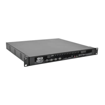
• Press the Port Up button to switch from the current port to the next port on the installation. Note: The figure shows the front panel of a B064-032-04-IP. The B064-032-02-IP, B064-016-02-IP and B064-016-04-IP contain all the same front-panel features as the B064-032-04-IP, except the B064-016-04-IP and B064-016-02-IP come with 16 ports instead of 32. - Page 7 Cat5e/6 cable connects between these ports and the SIUs to connect computer/servers to the KVM switch. Note: The figure above shows the rear panel of a B064-032-04-IP or B064-032-02-IP. The B064-016-04-IP and B064-016-02-IP differ in that it only has a single block of 16 KVM ports.
-
Page 8: Hardware Setup
• To help protect your system from sudden, transient increases and decreases in electrical power, it is recommended that you plug your devices into a Tripp Lite surge suppressor, line conditioner, or uninterruptible power supply (UPS). • Position system cables and power cables carefully to ensure that nothing rests on any cables. -
Page 9: Stacking
Hardware Setup Rack Mounting Safety Instructions • Before working on the rack, make sure that the stabilizers are secured to the rack, extended to the floor, and that the full weight of the rack rests on the floor. Install front and side stabilizers on a single rack or front stabilizers for joined multiple racks before working on the rack. •... -
Page 10: Two Stage Installations
8. Use the included grounding wire to ground the unit. Connect one end of the wire to the grounding terminal, and the other end of the wire to a suitable grounded object. 9. Plug the included power cord into the KVM switch’s Power Socket, and then into a Tripp Lite Surge Suppressor, Uninterruptible Power Supply (UPS) or PDU. -
Page 11: Hardware Setup
Two Stage Installations (continued) 5. Plug the power cord that came with the cascaded KVM switch into its Power Socket, and then into a Tripp Lite Surge Suppressor, Uninterruptible Power Supply (UPS) or PDU. 6. Repeat these steps for any other Second Stage units you wish to connect. -
Page 12: Super Administrator Setup
Super Administrator Setup The B064-Series KVM Switches supports three types of users, as shown in the table below: User Type Description Super Administrators have full access to all Ports and Devices in the KVM installation. They can manage all aspects of the Super Administrator installation. -
Page 13: Nic Settings
Super Administrator Setup NIC Settings The B064-Series KVM Switch is designed with two network interfaces. The NIC Setting section of the Network tab allows you to assign a single IP Address and DNS Server for both network interfaces, or to assign a separate address for each. Redundant NIC If Redundant NIC is enabled (the default), both interfaces use the IP address assigned to Network Adapter 1. -
Page 14: Changing The Super Administrator Login
Super Administrator Setup NIC Settings AP Windows Client For computers running Windows, the B064-Series KVM Switch’s IP address can be determined using the AP Windows Client that comes on the B064-Series KVM Switch CD. When you run the program it searches the network segment for B064-Series KVM Switch devices, and displays the results in a dialog box similar to the one below: Changing the Super Administrator Login... -
Page 15: Accessing The B064-Series Kvm Switch
Accessing the B064-Series KVM Switch The B064-Series KVM Switches can be accessed in the following ways: via local console, an internet browser, the AP Windows Client and/or the AP Java Client. Operating the KVM switch and configuring its settings is done the same regardless of how you connect to the B064-Series KVM Switch;... -
Page 16: Ap Windows Client Login
Accessing the B064-Series KVM Switch AP Windows Client Login In some cases, the Administrator may not want the B064-Series KVM Switches to be available via browser. The Windows AP Client allows Windows systems users access to the KVM switch without having to go through a browser. -
Page 17: The Tools Menu
Accessing the B064-Series KVM Switch The Tools Menu Tools Menu operations are performed after you connect to the B064-Series KVM Switch, but before you switch to remote view. There is only one option in the Tools Menu; Hotkey Setup. (See page 19 for details) AP Java Client Login In those cases in which the Administrator does not want the B064- Series KVM Switch to be available via browser and the remote user is... -
Page 18: The Osd Main Page
The OSD Main Page After you have successfully logged into the B064-Series KVM Switch, the OSD Main Page appears. This chapter describes the functionality of the OSD Main Page. The OSD Main Page When the OSD Main Page appears, the Port Access page is displayed. There is an icon bar across the top of the page, as well as a hidden Control Panel at the upper or lower center of the screen that becomes visible when you mouse over it:... -
Page 19: The Control Panel
The OSD Main Page The Control Panel The Control Panel consists of three rows: a row of icons at the top, with two text rows below. The Control Panel is only available when accessing the KVM switch remotely, and will not be accessible via the local console. -
Page 20: Video Options
The OSD Main Page Hotkey Setup (continued) The following steps will enable you to reconfigure the default Hotkey combinations: 1. Highlight the Action you wish to change and click Start. 2. Key in the Function keys (one at a time). The key names appear in the key field as you press them. 3. -
Page 21: Gamma Adjustment
The OSD Main Page Video Options (continued) The settings in the Video Options screen are given in the table below: Action Description Screen Position Adjust the horizontal and vertical position of the remote computer window by clicking the Arrow buttons. Auto-Sync Click Auto-Sync to have the vertical and horizontal offset values of the remote screen automatically detected and synchronized with the local screen. -
Page 22: The Message Board
The OSD Main Page The Message Board The B064-Series KVM Switch supports multiple user logins, which can possibly give rise to access conflicts. To alleviate this problem, a message board feature has been provided, allowing users to communicate with each other: The Button Bar The buttons on the Button Bar are toggles. -
Page 23: The On-Screen Keyboard
The OSD Main Page The On-Screen Keyboard The B064-Series KVM Switch supports an on-screen keyboard, available in multiple languages, with all the standard keys for each supported language. Click this icon to display the on-screen keyboard: To change languages, click the drop-down arrow on the on-screen keyboard next to the currently selected language and select the new language: Mouse Pointer Type... - Page 24 The OSD Main Page Manual Mouse Synchronization Windows Note: In order for the local and remote mice to synchronize, you must use the generic mouse driver supplied with the MS operating system. If you have a third party driver installed - such as one supplied by the mouse manufacturer - you must remove it.
-
Page 25: Port Access
Port Access When you log in to the KVM Switch, the OSD comes up with the Port Access page displayed. The page is organized into two main areas. All the ports that a user is permitted to access are listed in the Port Selection panel at the left of the page. -
Page 26: The Port Selection List
Port Access The Port Selection List • Users only see the switches and ports they have been given access to. • Ports and cascaded KVM switches are located under their parent switches. Click the Plus (+) in front of a switch to expand the tree and see the ports underneath it. -
Page 27: Port Properties
Port Access Port Naming (continued) 2. Key in a name for the port (or change/delete a previous one). The maximum number of characters allowed for a port name is 19. You can use any combination of letters, numbers, and symbols on the typewriter keys of keyboards with PC US English layout. 3. -
Page 28: Scan
Port Access Scan The Scan function automatically switches among all the ports that are accessible to the currently logged on user at regular intervals, allowing their activity to be monitored automatically. (See Auto Scanning on page 61 for details) Panel Array Mode Panel Array Mode is another way to monitor port activity without having to manually switch between ports. -
Page 29: Favorites
Port Access Favorites This is similar to a Bookmarks feature. Ports that you frequently visit can be saved in a list on this page. Simply open this page and select the port instead of hunting for it in the tree view. This feature is especially handy for larger, cascaded installations. Note: Each Favorites Bookmark that you create is a folder that you can add multiple ports to. -
Page 30: User Settings
Port Access User Settings The User Settings page allows users to set up their own individual working environments. The B064-Series KVM Switch stores a separate record for each user profile, and sets up the working environment according to the Username that was used to access the KVM switch. -
Page 31: Filter
Port Access Filter Filter allows you to search for particular events by date or by specific words or strings. When you access this function, the log filter dialog box displays at the bottom of the page: A description of the items is given in the table, below: Item Description Priority... -
Page 32: The Main Panel - Switches
Port Access The Main Panel – Switches If a switch is chosen in the Port Selection List, the Main panel looks similar to the one shown below: The main panel consists of three columns: Name, Config and View The Name column lists all of the users and groups that have been created. -
Page 33: The Status Panel
Port Access The Status Panel The Status panel provides information about the online status of a selected port, and the Server Interface Unit being used to connect it to a computer/server: Note: This panel is inactive when a KVM switch is selected in the Port Selection list. -
Page 34: User Management
User Management The User Management page allows Super Administrators and Administrators to create, modify and delete users and groups, as well as assign attributes to them. The User Management icon will not show up in User’s OSD screens, as they do not have access to this feature. The User Management Main Page The page is organized into two main areas. - Page 35 User Management Users - Adding Users (continued) 3. Enter the information for the user that you are adding. A description of each of the fields is given in the table below: Field Description Username Enter a username with a minimum of 6 and a maximum of 16 characters. Password Enter a password with a minimum of 8 and a maximum of 16 characters.
-
Page 36: Users - Modifying Users
User Management Users - Adding Users (continued) At this point you can do any of the following: • Assign the new user to a group by selecting the Groups tab in the user’s notebook. (See Assigning Users to a Group from the User’s Notebook on page 38 for details) •... -
Page 37: Groups - Modifying Groups
User Management Groups – Creating Groups (continued) 3. Enter the information for the Group that you are adding. A description of each of the fields in the Group notebook tab is given in the table below: Field Description Group Name Enter in a name for the Group you are adding here. -
Page 38: Assigning Users To A Group Via The User's Notebook
User Management Assigning Users to a Group via the User’s Notebook To assign a user to a group from the User’s notebook, do the following: 1. Select the user’s name from the User List or select the user’s name from the Main Panel and click Modify. Note: Super Administrators can not be assigned to a group, as they already have access to the entire installation. -
Page 39: Assigning Users To A Group Via The Group's Notebook
User Management Assigning Users to a Group via the Group’s Notebook To assign a user to a group from the Group notebook, do the following: 1. Select the group’s name in the Group list or select the group’s name in the Main Panel and click Modify. 2. -
Page 40: Device Assignment
User Management Device Assignment When a user logs into the B064-Series KVM Switch, the OSD comes up with the Port Access page displayed. All the ports that the user is permitted to access are listed in the Port Selection list on the left side of the page. Access permissions for those ports and the devices connected to them are assigned on a port-by-port basis from the User or Group list of the User Management page. -
Page 41: Device Management
Firmware Version This item displays the current firmware version number. You can reference it to see if there are newer versions available on the Tripp Lite website. IP Address 1 This item displays the IP address of the first network interface. -
Page 42: Ip Installer
Device Management IP Installer The IP Installer is an external Windows-based utility for assigning IP addresses to the B064-Series KVM Switch. The IP Installer searches the network for B064-Series KVM Switches and then displays them in a dialog box that allows you to configure the IP address of the unit. (See IP Installer on page 13 for details) The IP Installer section of the Network tab allows you to set different access rights for the IP Installer. -
Page 43: Security
Device Management Security The Security page contains settings that allow you to control access to the B064-Series KVM Switch. • IP and MAC Filters control access to the B064-Series KVM Switch based on the IP and/or MAC addresses of the computers attempting to access the system. -
Page 44: Mac Filtering
Device Management MAC Filtering To add a MAC filter: 1. Click Add. A dialog box similar to the one below appears: 2. Type in the desired MAC address and click OK. 3. Repeat these steps for any additional MAC addresses you want to filter. -
Page 45: Miscellaneous
Device Management Miscellaneous • The Clear Port Names button will delete all of the names that have been created for the ports of the B064-Series KVM Switch. Clicking on this button will first display a prompt that asks you if you are sure you want to clear all the port names. -
Page 46: Service
Device Management Service The Service page is composed of two panels: Access Ports and Log Server: Access Ports If a firewall is being used, the Administrator can specify the port numbers that the firewall will allow. If an invalid port number (or no port number) is specified, you may be blocked from accessing the B064-Series KVM Switch by the firewall. -
Page 47: Radius Settings
Device Management RADIUS Settings To allow authentication and authorization for the B064-Series KVM Switch through a RADIUS server, do the following: 1. Check the Enable check box in the RADIUS section. 2. Fill in the IP addresses and port numbers for the Preferred and Alternate RADIUS servers. 3. -
Page 48: Create A Start Menu Shortcut Entry
Device Management LDAP Configuration — Active Directory Install the Windows 2003 Support Tools 1. On your Windows Server CD, open the Support 2. In the right panel of the dialog box that comes up, double click SupTools.msi. 3. Follow along with the Installation Wizard to complete the procedure. Install the Active Directory Schema Snap-in 1. - Page 49 Device Management Extend and Update the Active Directory Schema Step 2 - Extend the Object Class With the New Attribute: a) Open Control Panel Administrative Tools Directory Schema. b) In the left panel of the screen that comes up, select Classes. c) In the right panel, right-click person: d) Select Properties;...
- Page 50 Device Management Extend and Update the Active Directory Schema d) Right-click on the user’s name and select Properties . e) On the Attribute Editor page of the dialog box that appears, select Permission from the list. Character Meaning Grants the user administrator privileges, allowing the user to configure the system. Allows the user to access the system via the Windows Client program.
-
Page 51: Openldap Server
Device Management Extend and Update the Active Directory Schema h) Click OK. When you return to the Attribute Editor page, the permission entry now reflects the new permissions: OpenLDAP Server OpenLDAP is an Open source LDAP server designed for UNIX platforms. A Windows version can be downloaded from: http://download.bergmans.us/openldap/openldap-2.2.29/openldap-2.2.29-db-4.3.29-openssl-0.9.8awin32_Setup.exe. -
Page 52: Openldap Server Configuration
Device Management OpenLDAP Server Configuration The main OpenLDAP configuration file, slapd.conf, has to be customized before launching the server. The modifications to the configuration file will do the following: • Specify the Unicode data directory. The default is ./ucdata. • Choose the required LDAP schemas. The core schema is mandatory. -
Page 53: Dit Creation
Device Management DIT Creation The LDAP Data Interchange Format (LDIF) is used to represent LDAP entries in a simple text format (please refer to RFC 2849). The figure below illustrates an LDIF file that creates the DIT for the B064- Series KVM Switch directory tree (shown in the figure, above). -
Page 54: Date/Time
Device Management Date/Time The Date/Time dialog page sets the B064-Series KVM Switch’s time parameters: Set the parameters according to the information below. Time Zone • To establish the time zone that the B064-Series KVM Switch is located in, choose the appropriate time zone from the drop-down list. - Page 55 Device Management OOBC (continued) Connection Setup Example (Windows XP) To set up a dial-in connection to the B064-Series KVM Switch under Windows XP, do the following: 1. From the Start menu, select Control Panel 2. When the Welcome to the New Connection Wizard dialog box appears, click Next to move on. 3.
-
Page 56: Maintenance
Maintenance The Maintenance function is used to upgrade the B064-Series KVM Switch’s firmware, as well as the firmware of the Server Interface Units (SIUs) used to connect its ports to the installed devices. Note: Super Administrators are the only users who are guaranteed access to the Maintenance section of the KVM. Administrators and Users can only access this function if they are given permission. -
Page 57: Upgrading The Firmware
Maintenance Upgrading the Firmware Follow the procedure below to upgrade the B064-Series KVM Switch firmware and the server interface units connected to its ports. Note: You can upgrade the firmware from any computer connected to the internet, even computers that are directly connected to the KVM switch. -
Page 58: B064-Series Kvm Switch Firmware Upgrade Recovery
Maintenance B064-Series KVM switch Firmware Upgrade Recovery Should the B064-Series KVM Switch firmware upgrade procedure fail, and the switch becomes unusable, the following firmware upgrade recovery procedure will resolve the problem: 1. Power off the switch. 2. Press and hold the Reset Switch on the front of the unit while powering the switch back on. This causes the switch to use the factory installed firmware version, rather than the version that you were attempting to upgrade the switch to. -
Page 59: Port Operation
Port Operation After you have successfully logged in (see Logging In, beginning on page 15), the B064-Series KVM Switch OSD Main Page appears with the Port Access tab selected: Note: Upon logging into the B064-Series KVM Switch, you will notice a control panel that appears at the top center of the screen. The control panel will automatically disappear after a few seconds;... -
Page 60: Panel Array Mode
Port Operation Panel Array Mode Clicking the Panel Array icon on the OSD Toolbar invokes Panel Array Mode. Under this mode, the OSD divides your screen into a grid of panels: Panel Array Toolbar The Panel Array Toolbar is located at the top center of the screen and provides shortcut navigation and control of the panel array. As with the control panel, the panel array toolbar will disappear after a few seconds. -
Page 61: Multiuser Operation
The B064-Series KVM Switches are designed to allow multiple users to simultaneously access the connected computers/servers. • The B064-032-02-IP and B064-016-02-IP are designed with two buses, which supports two simultaneous users. When multiple users are logging on at the same time, the first, third, fifth, etc., users to log in are all on the first bus. The second, fourth, sixth, etc., users to log in are all on the second bus. -
Page 62: Skip Mode
Port Operation Skip Mode Skip Mode allows you to switch ports in order to monitor the computers via the keyboard. As opposed to Auto Scan Mode, you can dwell on a particular port for as long or as little as you like. To access Skip Mode, you must first open up the OSD Toolbar by hitting the hotkey [Scroll Lock or Ctrl] twice. -
Page 63: The Log Server
The Log Server The Windows-based Log Server is an administrative utility that records all the events that take place on selected B064-Series KVM Switch units and writes them to a searchable database. This chapter describes how to install and configure the Log Server. Installation 1. -
Page 64: Configure
The Log Server Configure The Configure menu consists of three functions; Add, Edit and Delete. Select the Add function when you need to add a new B064-Series KVM Switch to the list of units that the Log Server records events for. Note: You must first add a B064-Series KVM Switch via the Add function before the Log Server can start recording its events. -
Page 65: Search
The Log Server Search Search allows you to search for events containing specific words or strings. When you access this function, a screen similar to the one below appears: A description of the items from the Search screen is given in the table below: Item Description Search Options... -
Page 66: Options
The Log Server Options The Options menu consists of only one function; Network Retry. Network Retry Network Retry allows you to set the number of seconds that the Log Server should wait before attempting to connect in the event that the previous connection attempt failed. -
Page 67: The Log Server
The Log Server The List Panel The List panel contains the following fields: Field Description Recording Determines whether the Log Server records log events for the corresponding B064-Series KVM Switch. If the Recording check box is checked, the field displays Recording, and log events are recorded. If the Recording check box is not checked, the field displays Paused, and log events are not recorded. -
Page 68: Appendix
Appendix General Operation Troubleshooting Problem Action Erratic Operation Reset the unit by pressing and holding the Reset button on the front of the unit for longer than three seconds. I can’t access the B064-Series KVM If the B064-Series KVM Switch is behind a router, the router’s Port Forwarding (also referred to as Switch, even though I have specified the Virtual Server) feature must be configured. -
Page 69: Panel Array Mode Troubleshooting
Appendix Panel Array Mode Troubleshooting Problem Action The video resolution is of low quality. The video quality decreases as you decrease the number of panels. Increase the number of panels that are displayed to improve video. When multiple remote users are logged The first user to invoke Panel Array Mode should set it to display at least four panels. -
Page 70: Specifications
5 Seconds Screen Blanker 0 Minutes (disabled) Beeper Accessible Ports F (Full) For all Users on all Ports B064-016-02-IP B064-016-04-IP Pushbutton, OSD and Hotkey (2) PS/2 Female and (2) USB Female Connectors (16) RJ45 Female (2) RJ45 Female (1) RJ45 Female IEC-320-C14 (3) USB 1.1 A Female... - Page 71 3-Year Limited Warranty TRIPP LITE warrants its products to be free from defects in materials and workmanship for a period of three (3) years from the date of initial purchase. TRIPP LITE’s obligation under this warranty is limited to repairing or replacing (at its sole option) any such defective products. To obtain service under this warranty, you must obtain a Returned Material Authorization (RMA) number from TRIPP LITE or an authorized TRIPP LITE service center.
- Page 72 Tripp Lite World Headquarters 1111 W. 35th Street, Chicago, IL 60609 USA (773) 869-1234 • www.tripplite.com 200811137 93-2852...
Need help?
Do you have a question about the B064-016-02-IP and is the answer not in the manual?
Questions and answers