Table of Contents
Advertisement
Quick Links
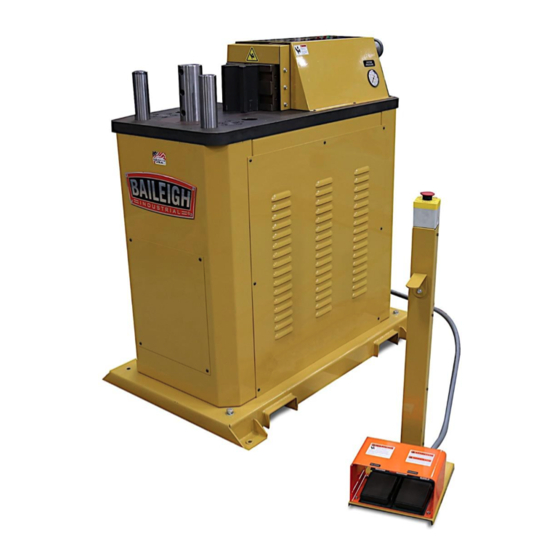
OPERATOR'S MANUAL
HORIZONTAL PRESS BRAKE
MODEL: HPB-20
Baileigh Industrial Holdings LLC P.O.
Box 531
Manitowoc, WI 54221-0531 Phone:
920.684.4990
Fax: 920.684.3944
baileigh-sales@jpwindustries.com
REPRODUCTION OF THIS MANUAL IN ANY FORM WITHOUT WRITTEN APPROVAL OF BAILEIGH INDUSTRIAL
HOLDINGS LLC IS PROHIBITED. Baileigh Industrial Holdings LLC, Inc. does not assume and hereby disclaims any
liability for any damage or loss caused by an omission or error in this Operator's Manual, resulting from accident,
negligence, or other occurrence.
Edition 1 02/2022
Advertisement
Table of Contents

Related Manuals for Baileigh HPB-20


Summary of Contents for Baileigh HPB-20
- Page 1 REPRODUCTION OF THIS MANUAL IN ANY FORM WITHOUT WRITTEN APPROVAL OF BAILEIGH INDUSTRIAL HOLDINGS LLC IS PROHIBITED. Baileigh Industrial Holdings LLC, Inc. does not assume and hereby disclaims any liability for any damage or loss caused by an omission or error in this Operator’s Manual, resulting from accident, negligence, or other occurrence.
-
Page 2: Table Of Contents
Table of Contents THANK YOU & WARRANTY ..................1 INTRODUCTION ......................3 GENERAL NOTES ......................3 SAFETY INSTRUCTIONS ....................4 SAFETY PRECAUTIONS ....................7 Dear Valued Customer: ....................7 TECHNICAL SPECIFICATIONS ..................9 TECHNICAL SUPPORT ....................9 UNPACKING AND CHECKING CONTENTS ..............10 TRANSPORTING AND LIFTING .................. -
Page 3: Thank You & Warranty
THANK YOU & WARRANTY Thank you for your purchase of a machine from Baileigh Industrial Holdings LLC. We hope that you find it productive and useful to you for a long time to come. Inspection & Acceptance. Buyer shall inspect all Goods within ten (10) days after receipt thereof. Buyer’s payment shall constitute final acceptance of the Goods and shall act as a waiver of the Buyer’s rights to inspect or reject the... - Page 4 Baileigh Industrial Holdings LLC makes every effort to ensure that our posted specifications, images, pricing and product availability are as correct and timely as possible. We apologize for any discrepancies that may occur. Baileigh Industrial Holdings LLC reserves the right to make any and all changes deemed necessary in the course of business including but not limited to pricing, product specifications, quantities, and product availability.
-
Page 5: Introduction
INTRODUCTION The quality and reliability of the components assembled on a Baileigh Industrial Holdings LLC machine guarantee near perfect functioning, free from problems, even under the most demanding working conditions. However, if a situation arises, refer to the manual first. If a solution cannot be found, contact the distributor where you purchased our product. -
Page 6: Safety Instructions
IMPORTANT PLEASE READ THIS OPERATORS MANUAL CAREFULLY It contains important safety information, instructions, and necessary operating procedures. The continual observance of these procedures will help increase your production and extend the life of the equipment. SAFETY INSTRUCTIONS LEARN TO RECOGNIZE SAFETY INFORMATION This is the safety alert symbol. - Page 7 SAVE THESE INSTRUCTIONS. Refer to them often and use them to instruct others. PROTECT EYES Wear safety glasses or suitable eye protection when working on or around machinery. PROTECT AGAINST NOISE Prolonged exposure to loud noise can cause impairment or loss of hearing.
- Page 8 BEWARE OF PINCH POINTS AND CRUSH HAZARD Keep hands and fingers from between the punch and die when bending materials to avoid possible injury. NEVER place your hands, fingers, or any part of your body in the die area of this machine. EMERGENCY STOP BUTTON In the event of incorrect operation or dangerous conditions, the machine can be stopped immediately by pressing the E-STOP button.
-
Page 9: Safety Precautions
All Baileigh machines should be used only for their intended use. • Baileigh does not recommend or endorse making any modifications or alterations to a Baileigh machine. Modifications or alterations to a machine may pose a substantial risk of injury to the operator or others and may do substantial damage to the machine. - Page 10 7. Dressing material edges. Always chamfer and deburr all sharp edges. 8. Do not force tool. Your machine will do a better and safer job if used as intended. DO NOT use inappropriate attachments in an attempt to exceed the machine’s rated capacity. 9.
-
Page 11: Technical Specifications
For specific application needs or future machine purchases contact the Sales Department at: baileigh-sales@jpwindustries.com, Phone: 920.684.4990, or Fax: 920.684.3944. Note: The photos and illustrations used in this manual are representative only and may not depict the actual color, labeling or accessories and may be intended to illustrate technique only. -
Page 12: Unpacking And Checking Contents
UNPACKING AND CHECKING CONTENTS Your Baileigh machine is shipped complete. Separate all parts from the packing material and check each item carefully. Make certain all items are accounted for before discarding any packing material. WARNING: SUFFOCATION HAZARD! Immediately discard any plastic bags and packing materials to eliminate choking and suffocation hazards to children and animals. -
Page 13: Transporting And Lifting
TRANSPORTING AND LIFTING NOTICE: Lifting and carrying operations should be carried out by skilled workers, such as a truck operator, crane operator, etc. If a crane is used to lift the machine, attach the lifting chain carefully, making sure the machine is well balanced. Follow these guidelines when lifting with truck or trolley: •... -
Page 14: Installation
INSTALLATION IMPORTANT: Consider the following when looking for a suitable location to place the machine: • Overall weight of the machine. • Weight of material being processed. • Sizes of material to be processed through the machine. • Space needed for auxiliary stands, worktables, or other machinery. •... -
Page 15: Anchoring The Machine
Anchoring the Machine • Once positioned, anchor the machine to the floor, as shown in the diagram. Use bolts and expansion plugs or sunken tie rods that connect through and are sized for the holes in the base of the stand. •... -
Page 16: Getting To Know Your Machine
GETTING TO KNOW YOUR MACHINE... - Page 17 Item Description Function Keyed pins which may be used for any manner Secondary Bend Pins of bending, counter bending, or support of other tooling. Main Bend Pin Keyed pin used to hold the bending punch. 40° wedge retained by the main bend pin used Bend Punch to create the desired bend angle with a generally square internal bend corner.
-
Page 18: Assembly And Setup
Item Description Function Stops all functions including the hydraulic Emergency Stop Switch pump operation. Pressing the Forward pedal extends the Ram Forward Foot Pedal bending cylinder. Pressing the Reverse pedal retracts the Ram Reverse Foot Pedal bending cylinder. Displays the operating pressure at the moment Hydraulic System Pressure Gauge of viewing. -
Page 19: Electrical
ELECTRICAL CAUTION: HAVE ELECTRICAL UTILITIES CONNECTED TO THE MACHINE BY A CERTIFIED ELECTRICIAN! Check if the available power supply is the same as listed on the machine nameplate. WARNING: Make sure the grounding wire (green) is properly connected to avoid electric shock. DO NOT switch the position of the green grounding wire if any electrical plug wires are switched during hookup. - Page 20 • Improper connection of the equipment-grounding conductor can result in risk of electric shock. The conductor with insulation having an outer surface that is green with or without yellow stripes is the equipment-grounding conductor. If repair or replacement of the electric cord or plug is necessary, do not connect the equipment-grounding conductor to a live terminal.
-
Page 21: Operation
OPERATION CAUTION: Always wear proper eye protection with side shields, safety footwear, and leather gloves to protect from burrs and sharp edges. When handling large heavy materials make sure they are properly supported. CAUTION: Keep hands and fingers clear of the punch and die. Stand off to the side of the machine to avoid getting hit with the material as it is being bent and formed. -
Page 22: Bending Allowance
BENDING ALLOWANCE To bend sheet metal accurately, you will need to consider the total length of each bend. This is referred to as bend allowance. Subtract the bend allowance from the sum of the outside dimensions of the workpiece to obtain the actual overall length or width of the piece. Because of differences in sheet metal hardness, and whether the bend is made with the grain or against it, exact allowances must sometimes be made by trial and error. -
Page 23: Machine Adjustments
MACHINE ADJUSTMENTS When making adjustments on the HPB-20, reference the following: Handwheels (#13): 1. The left handwheel controls the forward limit/bend degrees. a. To increase forward limit/bend degrees, turn the left handwheel counterclockwise (CCW). b. To decrease forward limit/bend degrees, turn the left handwheel clockwise (CW). -
Page 24: Lubrication And Maintenance
LUBRICATION AND MAINTENANCE WARNING: Make sure the electrical disconnect is OFF before working on the machine. Maintenance should be performed on a regular basis by qualified personnel. Always follow proper safety precautions when working on or around any machinery. • Check daily for any unsafe conditions and fix immediately. •... -
Page 25: Hydraulic System
Hydraulic System The hydraulic oil is the primary medium for transmitting pressure and also must lubricate the running parts of the pump. After installation of the machine and before machine startup, bring the oil level up to 90% of capacity. A shortage of hydraulic oil can cause hydraulic system breakdown and damage to major mechanical parts due to overheating. -
Page 26: Cabinet Assembly Parts Diagram
CABINET ASSEMBLY PARTS DIAGRAM... -
Page 27: Electrical Panel Assembly Parts Diagram
ELECTRICAL PANEL ASSEMBLY PARTS DIAGRAM... -
Page 28: Top Plate Assembly Parts Diagram
TOP PLATE ASSEMBLY PARTS DIAGRAM... -
Page 29: Top Plate/Cabinet Assembly Parts Diagram
TOP PLATE/CABINET ASSEMBLY PARTS DIAGRAM... -
Page 30: Cylinder Assembly Parts Diagram
CYLINDER ASSEMBLY PARTS DIAGRAM... -
Page 31: Sensor Assembly Parts Diagram
SENSOR ASSEMBLY PARTS DIAGRAM... -
Page 32: Guard Assembly Parts Diagram
GUARD ASSEMBLY PARTS DIAGRAM... -
Page 33: Tooling Assembly Parts Diagram
TOOLING ASSEMBLY PARTS DIAGRAM... -
Page 34: Pendant Assembly Parts Diagram
PENDANT ASSEMBLY PARTS DIAGRAM... -
Page 35: Parts List
Parts List Item Part No. Description Qty. HP20-6001-V2 MAIN TOP PLATE HP20-6004 ANGLE BRACKET HP20-6002 MASTER BLOCK HP20-6005 BOTTOM PLATE HP20-7006 SECONDARY BEND PIN HP20-7005 PRIMARY BEND PIN HP20-5001 HORIZONTAL PRESS CABINET HP20-6009 MASTER KEY HPT-40-VEE BEND NOSE HPT-2.0-2.5 DIE V BLOCK HP20-6010 WEAR PLATE... - Page 36 Item Part No. Description Qty. HP20-6052 PLATE SUPPORT HP20-6054 GUARD SPACER HP20-6055 CENTER POINTER HP20-6056 STOP POINTER HP20-7018 SENSOR SHAFT HP20-7019 GUIDE SHAFT PP-2144 PROXIMITY SENSOR HP20-6049 SCREW BLOCK PP-1385 1/2 LIGHT DUTY BEARING PP-0037 1/2" CLAMP COLLAR HP20-6060 SWITCH TRIGGER HP20-6053 HOME SWITCH ACTUATOR HP20-6059...
- Page 37 Item Part No. Description Qty. BSM-0205 M5 X .8 X 8 PPMS BSM-0132 M5 X 0.8 X 10 PPMS BS-0323 5/8-11X4 THREADED ROD M350-7A071 LEVELING FOOT BS-0223 5/8-11 HEX NUT BSM-0058 M10 X 1.5 X 20 HX FLG BSM-0067 M12 X 1.75 X 30 HEX FLG BSM-0068 M12 X 1.75 X 40 HEX FLG BSM-0141...
- Page 38 Item Part No. Description Qty. RP-6010 E-STOP UPRIGHT RP-6011 E-STOP UPRIGHT COVER PP-2063 E-STOP BOX RP-6009 PENDANT BASE PP-1143 FOOT PEDAL PP-0022 1/2" SEAL TIGHT ELBOW PP-2064 1/2 SEAL TIGHT TUBE PP-1099 (RED) CONTACTOR PP-1220 (GREEN TAB) PP-1098 EMERGENCY STOP BUTTON BSM-0045 M6 X 1.0 X 14 HX FLNG BSM-0121...
-
Page 39: Electrical Diagram
ELECTRICAL DIAGRAM... - Page 40 BAILEIGH INDUSTRIAL HOLDINGS LLC 1625 D , WI 54220 UFEK RIVE ANITOWOC : 920. 684. 4990 F : 920. 684. 3944 HONE www.baileigh.com...
Need help?
Do you have a question about the HPB-20 and is the answer not in the manual?
Questions and answers