Table of Contents
Advertisement
Quick Links
OPERATOR'S MANUAL
METAL FORMING SHRINKER STRETCHER
MODEL: MSS-14H (B8860)
REPRODUCTION OF THIS MANUAL IN ANY FORM WITHOUT WRITTEN APPROVAL OF BAILEIGH INDUSTRIAL
HOLDINGS LLC IS PROHIBITED. Baileigh Industrial Holdings LLC, Inc. does not assume and hereby disclaims any
liability for any damage or loss caused by an omission or error in this Operator's Manual, resulting from accident,
negligence, or other occurrence.
Rev. 07/2019
© 2019 Baileigh Industrial Holdings LLC
Advertisement
Table of Contents

Related Manuals for Baileigh Hare&Forbes MSS-14H


Summary of Contents for Baileigh Hare&Forbes MSS-14H
- Page 1 REPRODUCTION OF THIS MANUAL IN ANY FORM WITHOUT WRITTEN APPROVAL OF BAILEIGH INDUSTRIAL HOLDINGS LLC IS PROHIBITED. Baileigh Industrial Holdings LLC, Inc. does not assume and hereby disclaims any liability for any damage or loss caused by an omission or error in this Operator’s Manual, resulting from accident, negligence, or other occurrence.
-
Page 2: Table Of Contents
Table of Contents INTRODUCTION ......................1 GENERAL NOTES ......................1 SAFETY INSTRUCTIONS ....................2 SAFETY PRECAUTIONS ....................4 Dear Valued Customer: ....................4 TECHNICAL SPECIFICATIONS ..................6 UNPACKING AND CHECKING CONTENTS ..............6 Cleaning ........................7 TRANSPORTING AND LIFTING ..................7 INSTALLATION ....................... -
Page 3: Introduction
INTRODUCTION The quality and reliability of the components assembled on a Baileigh Industrial Holdings LLC machine guarantee near perfect functioning, free from problems, even under the most demanding working conditions. However, if a situation arises, refer to the manual first. If a solution cannot be found, contact the distributor where you purchased our product. -
Page 4: Safety Instructions
IMPORTANT PLEASE READ THIS OPERATORS MANUAL CAREFULLY It contains important safety information, instructions, and necessary operating procedures. The continual observance of these procedures will help increase your production and extend the life of the equipment. SAFETY INSTRUCTIONS LEARN TO RECOGNIZE SAFETY INFORMATION This is the safety alert symbol. - Page 5 SAVE THESE INSTRUCTIONS. Refer to them often and use them to instruct others. PROTECT EYES Wear safety glasses or suitable eye protection when working on or around machinery. HYDRAULIC HOSE FAILURE Exercise CAUTION around hydraulic hoses in case of a hose or fitting failure.
-
Page 6: Safety Precautions
Baileigh does not recommend or endorse making any modifications or alterations to a Baileigh machine. Modifications or alterations to a machine may pose a substantial risk of injury to the operator or others and may do substantial damage to the machine. - Page 7 7. Dressing material edges. Always chamfer and deburr all sharp edges. 8. Do not force tool. Your machine will do a better and safer job if used as intended. DO NOT use inappropriate attachments in an attempt to exceed the machines rated capacity. 9.
-
Page 8: Technical Specifications
TECHNICAL SPECIFICATIONS Mild Steel Capacity 14 ga. Aluminum Capacity 12 ga. Movement Hydraulic Down/Close, Pneumatic Up/Open Throat Depth 6" (152mm) Stand Included Electrical Power 240V, 50hz, 15A Motor 2hp (1.5kw) Air Supply 80-120psi (5.5-8.2bar) Shipping Weight 300 lbs. Shipping Dimensions 60"... -
Page 9: Cleaning
Your Baileigh machine is shipped complete. Separate all parts from the packing material and check each item carefully. Make certain all items are accounted for before discarding any packing material. WARNING: SUFFOCATION HAZARD! Immediately discard any plastic bags and packing materials to eliminate choking and suffocation hazards to children and animals. -
Page 10: Installation
NOTICE: Lifting and carrying operations should be carried out by skilled workers, such as a truck operator, crane operator, etc. If a crane is used to lift the machine, attach the lifting chain carefully, making sure the machine is well balanced. Follow these guidelines when lifting with truck or trolley: •... -
Page 11: Anchoring The Machine
• Remove scrap and waste materials regularly, and make sure the work area is free from obstructing objects. • If long lengths of material are to be fed into the machine, make sure that they will not extend into any aisles. •... -
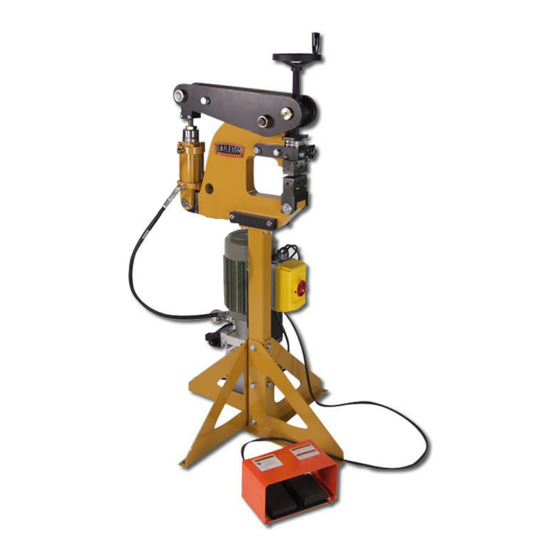
Page 12: Getting To Know Your Machine
GETTING TO KNOW YOUR MACHINE Item Description Function Foot Pedal Press the pedal to clamp the jaws together Down Solenoid Energized when clamping Extends with hydraulic pressure when clamping. Cylinder Retracts with pneumatic pressure. Gap Adjustment Increases or decrease the jaw gap. Stretch or shrink material ON/OFF Switch Starts and stops the motor. -
Page 13: Assembly And Set Up
ASSEMBLY AND SET UP WARNING: For your own safety, DO NOT connect the machine to the power source until the machine is completely assembled and you read and understand the entire instruction manual. Tooling Installation: This set up show how the tools should be installed for shrinking. - Page 14 In this view it shows the top die assemblies removed so you can see the jaw orientation. The jaws with serrations are to be used for shrinking. In this view it will shows how to remove the jaw caps. Insert a screwdriver into the machined slot to break the magnetic force.
- Page 15 Once the force from the magnet is released, grab onto the assembly and remove. In this view it shows the jaws installed for stretching. Note that the markings “U” are now pointing together, This is the reversing of the jaws from shrinking.
-
Page 16: Jaws
Here you will see both top and bottom mechanisms installed for stretching. Both show the “U” pointing at each other Also notice that the screw heads (A) point away from the material gap (B). Here is a completed setup for stretching. JAWS •... -
Page 17: Electrical
ELECTRICAL CAUTION: HAVE ELECTRICAL UTILITIES CONNECTED TO MACHINE BY A CERTIFIED ELECTRICIAN! Check if the available power supply is the same as listed on the machine nameplate. WARNING: Make sure the grounding wire (green) is properly connected to avoid electric shock. DO NOT switch the position of the green grounding wire if any electrical plug wires are switched during hookup. - Page 18 • Improper connection of the equipment-grounding conductor can result in risk of electric shock. The conductor with insulation having an outer surface that is green with or without yellow stripes is the equipment-grounding conductor. If repair or replacement of the electric cord or plug is necessary, do not connect the equipment-grounding conductor to a live terminal.
-
Page 19: Operation
OPERATION WARNING: DO NOT step on the foot pedal without having work material between the jaws. The jaws may chip or break causing injury from flying objects. CAUTION: Always wear proper eye protection with side shields, safety footwear, and leather gloves to protect from burrs and sharp edges. Keep hands and fingers clear of the dies. -
Page 20: Material Selection
Try using the tool with a sample piece of metal to get a feel for how it operates. Place the material in the middle of the jaw box and step down on the foot pedal to form the metal. Work the leading edge of the material first to break down the initial resistance of the metal. -
Page 21: Lubrication And Maintenance
LUBRICATION AND MAINTENANCE WARNING: Make sure the electrical disconnect is OFF before working on the machine. Maintenance should be performed on a regular basis by qualified personnel. Always follow proper safety precautions when working on or around any machinery. • Check daily for any unsafe conditions and fix immediately. •... -
Page 22: Parts Diagram
PARTS DIAGRAM... -
Page 26: Parts List
Parts List Item Part Number Description Qty. ME-M100-6A026 Stand Tube M100-6A025 M100 Leg Brace M12 X 1.75 X 20 Hex Flange ME-PS16-6A009 Stand Adaptor ME-PS16-6A001 Main Frame M10 X 1.5 X 20 Hex Flange M10 X 1.5 X 40 Hex Flange ME-M125-6A010-V3 Motor Mounting Plate M8 X 1.25 X 14... - Page 27 Item Part Number Description Qty. STD. 1"-14 Lock Nut PS16-7A009 Adjusting Shaft PP-0170 5.0 Handwheel Replacement Tooling Set PP-1163 PS16 Cylinder Assembly PS16-7A006 Adjusting Nut PS16-7A007 Lock Nut ME-PS16-6A007 Clevis End M8 X 1.25 X 40 SHCS PP-0056 1.0 Id X 1.5 Od X .125 THK PP-0035 1"...
-
Page 28: Tooling Block Parts Diagram
Tooling Block Parts Diagram Tooling Block Parts List Item Part Number Description Qty. PS16-6A010 Lower Tool Block PS16-6A015 Upper Tool Block PS16-6A011 Pivot Key PS16-6A012 Capture Plate PP-1177 Magnet PP-1178 Polyurethane STD. 1/4 X 3/8 Split Pin STD. .164-32 X 1/8 Set Screw STD. -
Page 29: Electrical Schematic
ELECTRICAL SCHEMATIC... - Page 30 General Machinery Safety Instructions Machinery House requires you to read this entire Manual before using this machine. 1. Read the entire Manual before starting 14. Use correct amperage extension cords. machinery. Machinery may cause serious injury if Undersized extension cords overheat and lose not correctly used.
- Page 31 Hydraulic/Pneumatic Shrinker Stretcher Safety Instructions Machinery House requires you to read this entire Manual before using this machine. 1. Maintenance. 9. Power Outage. Make sure the Hydraulic/ In the event of a power failure Pneumatic Shrinker Stretcher is turned off and during use of the machine, turn off all swtiches disconnect from the air before any inspection, to avoid possible sudden start up once power is...
Need help?
Do you have a question about the Hare&Forbes MSS-14H and is the answer not in the manual?
Questions and answers