Table of Contents
Advertisement
Quick Links
OPERATOR'S MANUAL
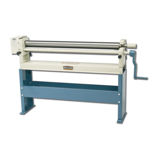
MANUAL SLIP ROLL
MODEL: SR-5016M
Baileigh Industrial Holdings LLC
P.O. Box 531
Manitowoc, WI 54221-0531
Phone: 920.684.4990
Fax: 920.684.3944
sales@baileigh.com
REPRODUCTION OF THIS MANUAL IN ANY FORM WITHOUT WRITTEN APPROVAL OF BAILEIGH INDUSTRIAL
HOLDINGS LLC IS PROHIBITED. Baileigh Industrial Holdings LLC, Inc. does not assume and hereby disclaims any
liability for any damage or loss caused by an omission or error in this Operator's Manual, resulting from accident,
negligence, or other occurrence.
Rev. 07/2020
© 2020 Baileigh Industrial Holdings LLC
Advertisement
Table of Contents

Subscribe to Our Youtube Channel
Related Manuals for Baileigh SR-5016M


Summary of Contents for Baileigh SR-5016M
- Page 1 REPRODUCTION OF THIS MANUAL IN ANY FORM WITHOUT WRITTEN APPROVAL OF BAILEIGH INDUSTRIAL HOLDINGS LLC IS PROHIBITED. Baileigh Industrial Holdings LLC, Inc. does not assume and hereby disclaims any liability for any damage or loss caused by an omission or error in this Operator’s Manual, resulting from accident, negligence, or other occurrence.
-
Page 2: Table Of Contents
Table of Contents THANK YOU & WARRANTY ..................1 INTRODUCTION ......................3 GENERAL NOTES ......................3 SAFETY INSTRUCTIONS ....................4 SAFETY PRECAUTIONS ....................6 Dear Valued Customer: ....................6 TECHNICAL SPECIFICATIONS ..................8 TECHNICAL SUPPORT ....................8 UNPACKING AND CHECKING CONTENTS ..............9 TRANSPORTING AND LIFTING .................. -
Page 3: Thank You & Warranty
THANK YOU & WARRANTY Thank you for your purchase of a machine from Baileigh Industrial Holdings LLC. We hope that you find it productive and useful to you for a long time to come. Inspection & Acceptance. Buyer shall inspect all Goods within ten (10) days after receipt thereof. Buyer’s payment shall constitute final acceptance of the Goods and shall act as a waiver of the Buyer’s rights to inspect or... - Page 4 We apologize for any discrepancies that may occur. Baileigh Industrial Holdings LLC reserves the right to make any and all changes deemed necessary in the course of business including but not limited to pricing, product specifications, quantities, and product availability.
-
Page 5: Introduction
INTRODUCTION The quality and reliability of the components assembled on a Baileigh Industrial Holdings LLC machine guarantee near perfect functioning, free from problems, even under the most demanding working conditions. However, if a situation arises, refer to the manual first. If a solution cannot be found, contact the distributor where you purchased our product. -
Page 6: Safety Instructions
IMPORTANT PLEASE READ THIS OPERATORS MANUAL CAREFULLY It contains important safety information, instructions, and necessary operating procedures. The continual observance of these procedures will help increase your production and extend the life of the equipment. SAFETY INSTRUCTIONS LEARN TO RECOGNIZE SAFETY INFORMATION This is the safety alert symbol. - Page 7 SAVE THESE INSTRUCTIONS. Refer to them often and use them to instruct others. PROTECT EYES Wear safety glasses or suitable eye protection when working on or around machinery. PROTECT AGAINST NOISE Prolonged exposure to loud noise can cause impairment or loss of hearing.
-
Page 8: Safety Precautions
Baileigh does not recommend or endorse making any modifications or alterations to a Baileigh machine. Modifications or alterations to a machine may pose a substantial risk of injury to the operator or others and may do substantial damage to the machine. - Page 9 7. Dressing material edges. Always chamfer and deburr all sharp edges. 8. Do not force tool. Your machine will do a better and safer job if used as intended. DO NOT use inappropriate attachments in an attempt to exceed the machine’s rated capacity. 9.
-
Page 10: Technical Specifications
(other than die sets and blades). For specific application needs or future machine purchases contact the Sales Department at: sales@baileigh.com, Phone: 920.684.4990, or Fax: 920.684.3944. Note: The photos and illustrations used in this manual are representative only and may not depict the actual color, labeling or accessories and may be intended to illustrate technique only. -
Page 11: Unpacking And Checking Contents
UNPACKING AND CHECKING CONTENTS Your Baileigh machine is shipped complete. Separate all parts from the packing material and check each item carefully. Make certain all items are accounted for before discarding any packing material. WARNING: SUFFOCATION HAZARD! Immediately discard any plastic bags and packing materials to eliminate choking and suffocation hazards to children and animals. -
Page 12: Transporting And Lifting
TRANSPORTING AND LIFTING NOTICE: Lifting and carrying operations should be carried out by skilled workers, such as a truck operator, crane operator, etc. If a crane is used to lift the machine, attach the lifting chain carefully, making sure the machine is well balanced. Follow these guidelines when lifting with truck or trolley: •... -
Page 13: Anchoring The Machine
This machine may be mounted on either an existing work bench which is secured to the floor, or on the optional stand which is secured to the floor. If you intend to mount the Baileigh machine on a workbench be aware of the following: • Overall weight of the machine and the weight of material being processed. -
Page 14: Operation
(1.51mm) x 50” (1270mm) wide mild steel. The SR-5016M slip roller has three 3” (76.2mm) diameter rolls. The two front rolls, one placed vertically above the other are clamping rolls. The top roll is fixed and the bottom roll is adjustable with two knobs (A). -
Page 15: Plate Rolling Procedure
Always make sure the gap along the full length of the rolls is consistent. (fig. 3). If the rolls are not adjusted exactly parallel, the material will spiral during the rolling process. Because material springback varies with the kind of material being formed, only by test forming several pieces can the correct adjustments be made. - Page 16 1. Load the material forward to a point as in view “A”. 2. Turn the two adjusting knobs (B) clockwise (cw) until you have an approximate radius to your finished piece. See view “B” 3. Back the piece out, turn the piece part, and repeat the above sequence for the other end. See view “C”...
-
Page 17: Removing Rolled Piece Part
Removing Rolled Piece Part 1. Turn the two bottom roll bolts (A) counterclockwise (ccw) which will lower the bottom front roll. 2. Grasp the clamp top roll lock handle head as shown in (fig. 5), and pull out, (fig. 6). 3. -
Page 18: Bending Allowance
BENDING ALLOWANCE In order to bend sheet metal accurately, you will need to consider the total length of each bend. This is referred to as bend allowance. Subtract the bend allowance from the sum of the outside dimensions of the piece part to obtain the actual overall length or width of the piece. Because of differences in sheet metal hardness, and whether the bend is made with the grain or against it, exact allowances must sometimes be made by trial and error. -
Page 19: Lubrication And Maintenance
LUBRICATION AND MAINTENANCE WARNING: Maintenance should be performed on a regular basis by qualified personnel. Always follow proper safety precautions when working on or around any machinery. • Check daily for any unsafe conditions and fix immediately. • Check that all nuts and bolts are properly tightened. •... -
Page 20: Parts Identification Drawing
PARTS IDENTIFICATION DRAWING... -
Page 21: Parts Identification List
Parts Identification List Item Part No. Description SR5016M-1 Side Frame Right SR5016M-2 Side Frame Left SR5016M-3 Fixed Base SR5016M-4 Crank Handle SR5016M-5 Top Cover SR5016M-6 Clamp Handle SR5016M-7 Rear Roll SR5016M-8 Upper Roll SR5016M-9 Lower Roll SR5016M-10 Driving Rod SR5016M-11 Adjusting Screw W3/4"-10 SR5016M-12 Pin. - Page 22 Item Part No. Description SR5016M-37 Set Screw W5/16" x 5/16" SR5016M-38 Set Screw W3/8" x 1" SR5016M-39 Set Screw W3/8" x 3/8" SR5016M-44 Spring Washer SR5016M-45 Washer SR5016M-46 Nut W1/2" SR5016M-47 Nut W3/8" SR5016M-61 W3/8" x 1-1/4" SHCS SR5016M-63 Screw M6 x 10...
- Page 23 NOTES...
- Page 24 BAILEIGH INDUSTRIAL HOLDINGS LLC 1625 D , WI 54220 UFEK RIVE ANITOWOC : 920. 684. 4990 F : 920. 684. 3944 HONE www.baileigh.com BAILEIGH INDUSTRIAL HOLDINGS LTD. U WIFT OINT WIFT ALLEY NDUSTRIAL STATE UGBY , CV21 1QH U IDLANDS...
Need help?
Do you have a question about the SR-5016M and is the answer not in the manual?
Questions and answers