Table of Contents
Advertisement
Quick Links
OPERATOR'S MANUAL
VERTICAL MILL
MODEL: VM-936E-1
Baileigh Industrial, Inc.
P.O. Box 531
Manitowoc, WI 54221-0531
Phone: 920.684.4990
Fax: 920.684.3944
sales@baileighindustrial.com
REPRODUCTION OF THIS MANUAL IN ANY FORM WITHOUT WRITTEN APPROVAL OF BAILEIGH INDUSTRIAL, INC.
IS PROHIBITED. Baileigh Industrial, Inc. does not assume and hereby disclaims any liability for any damage or loss
caused by an omission or error in this Operator's Manual, resulting from accident, negligence, or other occurrence.
Rev. 10/2014
© 2014 Baileigh Industrial, Inc.
Advertisement
Table of Contents

Subscribe to Our Youtube Channel
Related Manuals for Baileigh VM-936E-1


Summary of Contents for Baileigh VM-936E-1
- Page 1 REPRODUCTION OF THIS MANUAL IN ANY FORM WITHOUT WRITTEN APPROVAL OF BAILEIGH INDUSTRIAL, INC. IS PROHIBITED. Baileigh Industrial, Inc. does not assume and hereby disclaims any liability for any damage or loss caused by an omission or error in this Operator’s Manual, resulting from accident, negligence, or other occurrence.
-
Page 2: Table Of Contents
Table of Contents THANK YOU & WARRANTY ..................1 INTRODUCTION ......................3 GENERAL NOTES ......................3 SAFETY INSTRUCTIONS ....................4 SAFETY PRECAUTIONS ....................7 TECHNICAL SPECIFICATIONS ..................9 TECHNICAL SUPPORT ....................9 UNPACKING AND CHECKING CONTENTS ..............10 Cleaning ........................11 TRANSPORTING AND LIFTING .................. - Page 3 ELECTRICAL ENCLOSURE ..................49 CONTROL PENDENT ....................50 ELECTRICAL COMPONENTS ..................50 TROUBLESHOOTING ....................51...
-
Page 4: Thank You & Warranty
THANK YOU & WARRANTY Thank you for your purchase of a machine from Baileigh Industrial. We hope that you find it productive and useful to you for a long time to come. Inspection & Acceptance. Buyer shall inspect all Goods within ten (10) days after receipt thereof. Buyer’s payment shall constitute final acceptance of the Goods and shall act as a waiver of the Buyer’s rights to inspect or... - Page 5 Baileigh Industrial makes every effort to ensure that our posted specifications, images, pricing and product availability are as correct and timely as possible. We apologize for any discrepancies that may occur. Baileigh Industrial reserves the right to make any and all changes deemed necessary in the course of business including but not limited to pricing, product specifications, quantities, and product availability.
-
Page 6: Introduction
After receiving your equipment remove the protective container. Do a complete visual inspection, and if damage is noted, photograph it for insurance claims and contact your carrier at once, requesting inspection. Also contact Baileigh Industrial and inform them of the unexpected occurrence. Temporarily suspend installation. -
Page 7: Safety Instructions
IMPORTANT PLEASE READ THIS OPERATORS MANUAL CAREFULLY It contains important safety information, instructions, and necessary operating procedures. The continual observance of these procedures will help increase your production and extend the life of the equipment. SAFETY INSTRUCTIONS LEARN TO RECOGNIZE SAFETY INFORMATION This is the safety alert symbol. - Page 8 SAVE THESE INSTRUCTIONS. Refer to them often and use them to instruct others. PROTECT EYES Wear safety glasses or suitable eye protection when working on or around machinery. PROTECT AGAINST NOISE Prolonged exposure to loud noise can cause impairment or loss of hearing.
- Page 9 HIGH VOLTAGE USE CAUTION IN HIGH VOLTAGE AREAS. DO NOT assume the power to be off. FOLLOW PROPER LOCKOUT PROCEDURES. EMERGENCY STOP BUTTON In the event of incorrect operation or dangerous conditions, the machine can be stopped immediately by pressing the E-STOP button.
-
Page 10: Safety Precautions
SAFETY PRECAUTIONS Metal working can be dangerous if safe and proper operating procedures are not followed. As with all machinery, there are certain hazards involved with the operation of the product. Using the machine with respect and caution will considerably lessen the possibility of personal injury. However, if normal safety precautions are overlooked or ignored, personal injury to the operator may result. - Page 11 11. Do not overreach. Maintain proper footing and balance at all times. DO NOT reach over or across a running machine. 12. Stay alert. Watch what you are doing and use common sense. DO NOT operate any tool or machine when you are tired. 13.
-
Page 12: Technical Specifications
TECHNICAL SPECIFICATIONS Spindle Speeds Distance from Spindle to Table Maximum 15" (380mm) Distance from Spindle to Base Maximum 15-3/4" (400mm) Distance from Spindle to Column Maximum 5-1/4" (134mm) Spindle Speed Range 240-1550 RPM Longitudinal Feed Rate 0-175"/min (0-4445mm/min) Table Size 9"... -
Page 13: Unpacking And Checking Contents
UNPACKING AND CHECKING CONTENTS Your Baileigh machine is shipped complete in one crate. Separate all parts from the packing material and check each item carefully. Make certain all items are accounted for before discarding any packing material. WARNING: SUFFOCATION HAZARD! Immediately discard any plastic bags and packing materials to eliminate choking and suffocation hazards to children and animals. -
Page 14: Cleaning
Cleaning Your machine may be shipped with a rustproof waxy oil coating and grease on the exposed unpainted metal surfaces. To remove this protective coating, use a degreaser or solvent cleaner. For a more thorough cleaning, some parts will occasionally have to be removed. DO NOT USE acetone or brake cleaner as they may damage painted surfaces. -
Page 15: Transporting And Lifting
TRANSPORTING AND LIFTING CAUTION: Lifting and carrying operations should be carried out by skilled workers, such as a truck operator, crane operator, etc. If a crane is used to lift the machine, attach the lifting chain carefully, making sure the machine is well balanced. - Page 16 Follow these guidelines when lifting: Raising the Head 1. Remove the hand wheel (A). 2. Loosen the four cap nuts (B) 1/2 turn to unlock the head. DO NOT remove these nuts unless you are prepared to remove the head. 3.
-
Page 17: Installation
INSTALLATION IMPORTANT: Consider the following when looking for a suitable location to place the machine: Overall weight of the machine. Weight of material being processed. Sizes of material to be processed through the machine. Space needed for auxiliary stands, work tables, or other machinery. ... -
Page 18: Anchoring The Machine
Set machine by leveling the work table lengthwise and crosswise with a precision level. OVERVIEW OF MACHINE FUNCTIONALITY The Baileigh VM-936E-1 vertical Milling machine forms shapes by removing metal from the piece part. Various tooling is placed into the head spindle and positioned into just about any configuration you can imagine. -
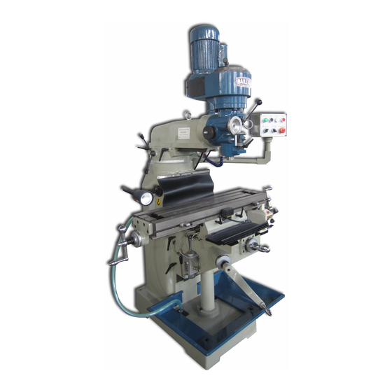
Page 19: Getting To Know Your Machine
GETTING TO KNOW YOUR MACHINE... - Page 20 A. Drawbar Access – Access the drawbar. B. Motor – 2.0hp (1.5kw) to power the vertical mill. C. Spindle Brake – Move in either direction to stop spindle once power has been turned off. D. Belt Tension Handle – Used to add or remove tension to the belt. E.
- Page 21 T. Manual One-Shot Oiler – Pull down on the handle to distribute oil to the various designated locations. U. Locking Handles – Turning the handles clockwise (cw) locks the table (Z axis) direction. V. Locking Handle – Turn clockwise (cw) to lock the (Y axis) of the table.
- Page 22 W. Power Button – Press to start the main motor. Button is illuminated when main disconnect is X. Right Thread – Press when tapping to create right turn threads. Y. Left Thread – Press when tapping to create left turn threads. Z.
-
Page 23: Electrical
ELECTRICAL CAUTION: HAVE ELECTRICAL UTILITIES CONNECTED TO MACHINE BY A CERTIFIED ELECTRICIAN! Check if the available power supply is the same as listed on the machine nameplate. WARNING: Make sure the grounding wire (green) is properly connected to avoid electric shock. DO NOT switch the position of the green grounding wire if any electrical plug wires are switched during hookup. -
Page 24: Test Running
Also check that the spindle direction switch is operating correctly. If any vibrations are noticed or you hear any unusual noises, stop the machine immediately and consult the Troubleshooting section of this manual, or if needed contact the service department at Baileigh Industrial. -
Page 25: Spindle Break-In
SPINDLE BREAK-IN After successfully completing the test run, it is recommended to break-in the spindle using the following procedure, to avoid rapid wear of the spindle when placed into operation. 1. Make sure the mill has been properly lubricated. 2. DISCONNECT POWER TO THE MACHINE. 3. -
Page 26: Machine Operations And Adjustments
If normal safety precautions are overlooked or ignored, serious personal injury may occur. Locks Table locks The VM-936E-1 has various locking “X” travel handles to secure the table in position when controlled movement of the piece part and table are not needed during operation. - Page 27 CAUTION: Always keep the table locked in place unless controlled movement is required. Table movement during machining operations could cause the tool to bind with the piece part, resulting in damage to the tool and piece part, or serious personal injury. Table Limit Stops Position the limit stops along the limit stop tracks to confine the travel distance of the table.
-
Page 28: Turret Rotation
“Z” Axis: Each increment of rotation on the dial equals .001” (.025mm) so one complete rotation of the dial will give 0.10” (2.5mm) of linear table travel on the “Y” axis. .001" .025mm figure 12 Turret Rotation The turret rotates 90° to the left and 90° to the right from the center “0”... -
Page 29: Changing Belt Speeds
Changing Belt Speeds 1. DISCONNECT POWER TO THE MILL. 2. Remove the two covers on the head to expose the belt change cavity. 3. Loosen the nut as indicated with the arrow and the nut on the opposite side. 4. Move the belt tension handle “D” to loosen the belt. -
Page 30: Calculating Spindle Speed
Calculating Spindle Speed 1. To select the correct spindle speed (RPM) Cutting Speeds for High Speed Steel (HSS) needed for a particular milling operation, first Cutting Tools select the type material you will be using from Piece Part Material Cutting Speed (SFM) the chart in (fig. -
Page 31: Downfeed Controls
Downfeed Controls A. Quill Stop (A, fig. 18) located on the front of the head and is used in conjunction with the micrometer adjusting nut for predetermined depth. B. Downfeed Stop & Lock Wheels (B, fig. 18) Stops the downfeed travel when the quill stop reaches this point. -
Page 32: Using The Drawbar
Using the Drawbar This milling machine comes with a 7/16”-20 x 19.75” (500mm) long drawbar. To load a tool into the spindle: 1. DISCONNECT POWER TO THE MILL. 2. Locate the drawbar (A) and clean any debris from the mating surfaces of the spindle and the collet. -
Page 33: Auto Tapping Operation
AUTO TAPPING OPERATION 1. Loosen the retaining nut (A). 2. Adjust the nut (B) up or down along screw (C) to the desired tapping distance/depth. The distance from top surface of nut (A) to bottom surface of dog (D) is the controlling depth of tapping. 3. -
Page 34: Gib Adjustments
Gib Adjustments Knee Gib Adjustment (Item #53 on Base Assembly) Adjust gib screw #18 for proper travel and to remove excess play. Note: When adjusting the gibs, always start with the knee, then the saddle, and finally the table. figure 23 Saddle Gib Adjustment (Item #47 on Base Assembly) Adjust gib screw #18 for proper travel and to remove excess play. - Page 35 Head Alignment The scale on the ram adapter for head rotation is to be used as a guide only. Close tolerance work will require the use of a dial indicator to make sure the head is 90° to the table in the “X” axis. Longitudinal &...
-
Page 36: Lubrication And Maintenance
LUBRICATION AND MAINTENANCE WARNING: Make sure the electrical disconnect is OFF before working on the machine. Maintenance should be performed on a regular basis by qualified personnel. Always follow proper safety precautions when working on or around any machinery. Check daily for any unsafe conditions and fix immediately. ... -
Page 37: Head Assembly
HEAD ASSEMBLY... -
Page 38: Upper Head Assembly Parts List
Upper Head Assembly Parts List Item Part No. Description Size Qty. MDM0S -01 Castle Nut MDM0S -02 Lock Nut TS-1523041 Hex Socket Cap Screw M6x12 MDM0S -04 Cover MDM0S -05 Taper Sleeve MDM0S -06 Spring MDM0S -07 Transmission Sleeve MDM0S -08T Worm Gear MDM0S -09 Spring Washer... - Page 39 Item Part No. Description Size Qty. MDM0S -37 Worm Shaft MDM0S -38 Full Dog Point Set Screw M5x6 TS-1522011 Set Screw M5x6 MDM0S -40T Bushing MDM0S -41 Spring Pin Ø3x14 MDM0S -42T Worm MDM0S -43T Shaft MDM0S -44 Flat Key 4x4x12 MDM0S -45T Bushing...
- Page 40 Item Part No. Description Size Qty. MDM0S -80T Protection Cover MDM0S -81 Spindle Shaft MDM0S -82 Full Dog Point Set Screw M5x6 TS-1522011 Set Screw M5x6 MDM0S -84 Stud M12x50 MDM0S -85 Spring Washer TS-1540081 Hex. Nut MDM0S -87 Limit Plate MDM0S -88 Rivet Ø2...
-
Page 41: S Upper Head Assembly
S UPPER HEAD ASSEMBLY... -
Page 42: S Upper Head Assembly Parts List
S Upper Head Assembly Parts List Item Part No. Description Size Qty. VM-G22-1 Spacer VM-G22 Draw Bar VM-M3-1 Knob VM-M3-3 Break Handle VM-M11-1 Jam Nut TS-1514021 Hex Socket Cap Screw M6*6 VM-M4 Fixed Cover VM-M3-5 Brake Rod BB-6007ZZ Ball Bearing 6007ZZ VM-M2 Brake... - Page 43 Item Part No. Description Size Qty. VM-M23-1 Stud M12*50 TS-1540081 Hex. Nut TS-1550081 Flat Washer VM-M23-1 Stud M12*50 VB-A29 Belt A720 VM-3307 Spindle Speed Chart VM-3233 Spring VM-M2-2 Cross Round Cap Screw...
-
Page 44: Leadscrew Assembly
LEADSCREW ASSEMBLY... -
Page 45: Leadscrew Assembly Parts List
Leadscrew Assembly Parts List Item Part No. Description Size Qty. MDM0S-LA01 Castle Nut MDM0S-LA02 Handle MDM0S-LA03 Ball Handle MDM0S-LA04 Knurled Nut MDM0S-LA05 Dial MDM0S-LA06 Dial Holder MDM0S-LA06A Dial Holder Assembly (Include #4,5,6,30) MDM0S-LA07 Dial Holder MDM0S-LA07A Dial Holder Assembly (Include #4,5,7,30) MDM0S-LA08 Bearing Retaining Cover TS-1515011... -
Page 46: Base Assembly
BASE ASSEMBLY... -
Page 47: Base Assembly Parts List
Base Assembly Parts List Item Part No. Description Size Qty. MDM0S-BA01 Worm Gear MDM0S-BA02 Taper Pin Ø8x150 TS-1505031 Hex Socket Cap Screw M10x25 MDM0S-BA04 Graduation Dial MDM0S-BA04-1 Graduation Dial Plate MDM0S-BA05 Taper Pin Ø8x130 TS-1515011 Hex Socket Cap Screw M8x16 MDM0S-BA07 MDM0S-BA08 Eye Bolt... - Page 48 Item Part No. Description Size Qty. TS-1523051 Set Screw M6x15 MDM0S-BA32 Elevation Screw Stand MDM0S-BA33 Hex Socket Cap Screw M10x30 MDM0S-BA34 Strainer Net 34-1 MDM0S-BA34-1 Screw M5x12 MDM0S-BA35 Table 3/8”PT MDM0S-BA36 Oil Plug MDM0S-BA38 Hex. Socket Screw M8x20 MDM0S-BA39 Stop Ring MDM0S-BA40 T-Nut MDM0S-BA41...
- Page 49 Item Part No. Description Size Qty. Dial Holder Assembly (Include MDM0S-BA66A #66,67,68,69,71,90) MDM0S-BA67 Dial MDM0S-BA68 Knurled Nut MDM0S-BA69 Clutch Insert MDM0S-BA71 Hand Lever MDM0S-BA73 Hand Grip MDM0S-BA74 Helical Bevel Gear BB-51104 Thrust Bearing 51104 MDM0S-BA76 Elevating Screw 76-1 MDM0S-BA76-1 Bushing MDM0S-BA77 Upper Chip Guard MDM0S-BA78...
-
Page 50: One Shot Lubrication System
ONE SHOT LUBRICATION SYSTEM One Shot Lubrication System Parts List Item Part No. Description Size Qty. MDM0S-OS01 Hand Oiling Pump MDM0S-OS02 Aluminum Pipe MDM0S-OS03 Oil Regulating Distributor MDM0S-OS04 T-Joint MDM0S-OS05 Flexible Steel Tube MDM0S-OS06 Check Joint MDM0S-OS07 Elbow Joint TS-1514021 Hex Socket Cap Screw M6x16 TS-1503061... -
Page 51: Electrical Diagram
ELECTRICAL DIAGRAM... -
Page 52: Electrical Enclosure
ELECTRICAL ENCLOSURE... -
Page 53: Control Pendent
CONTROL PENDENT ELECTRICAL COMPONENTS Item Parts Specification Transformer JBK-5-63VA, 220/24 Main Disconnect Switch JCH13-20-AC21A - JUCHE Breaker DZ47-63/2P, D10 Breaker DZ47-63/1P, D3 Timer Relay H3Y-2-C 24VAC/5A 110/220 – 24VDC Power Supply KM1 – KM3, KA Contactor 22E, CJX1-9 Contactor 22E, 3TB40 22-0X Relay MY4N-J-DC24 Emergency Stop... -
Page 54: Troubleshooting
TROUBLESHOOTING WARNING: Make sure the electrical disconnect is OFF before working on the machine. FAULT PROBABLE CAUSE REMEDY 1. Wrong voltage 1. Make sure the machine voltage matches the nameplate. 2. The plug or receptacle is wired 2. Test the contacts and correct Vertical Mill Does incorrectly the wiring. - Page 55 1. Locks are tightened down. 1. Loosen locks for proper movement. Table is Hard to 2. Chips have plugged up the ways 2. Clean away chips frequently. Move 3. Ways need lubrication. 3. Use one-shot oiler to lubricate ways. 1. Wrong feed rate/spindle speed. 1.
- Page 56 , WI 54220 UFEK RIVE ANITOWOC : 920. 684. 4990 F : 920. 684. 3944 HONE www.baileigh.com BAILEIGH INDUSTRIAL, INC. 1455 S. C , CA 91761 AMPUS VENUE NTARIO : 920. 684. 4990 F : 920. 684. 3944 HONE BAILEIGH INDUSTRIAL LTD. U...
Need help?
Do you have a question about the VM-936E-1 and is the answer not in the manual?
Questions and answers