Table of Contents
Advertisement
MAINTENANCE AND PARTS
MANUAL
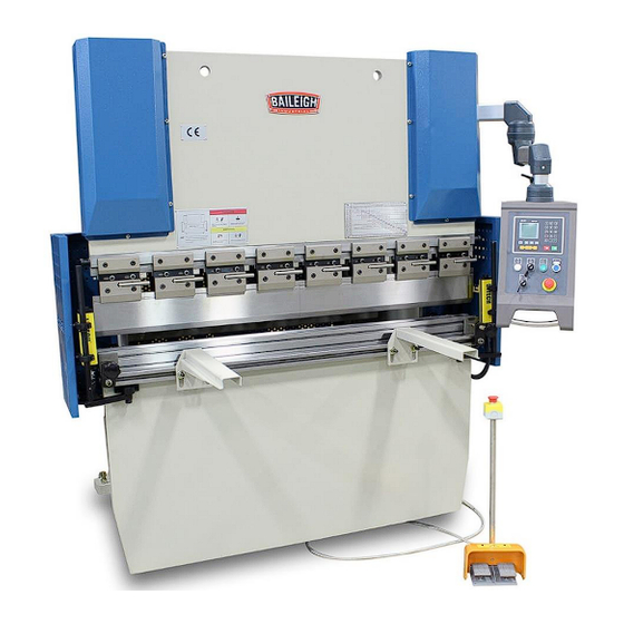
HYDRAULIC PRESS BRAKE
MODEL: BP-3305CNC
Baileigh Industrial Holdings LLC
P.O. Box 531
Manitowoc, WI 54221-0531
Phone: 920.684.4990
Fax: 920.684.3944
sales@baileigh.com
REPRODUCTION OF THIS MANUAL IN ANY FORM WITHOUT WRITTEN APPROVAL OF BAILEIGH INDUSTRIAL
HOLDINGS LLC IS PROHIBITED. Baileigh Industrial Holdings LLC, Inc. does not assume and hereby disclaims any
liability for any damage or loss caused by an omission or error in this Operator's Manual, resulting from accident,
negligence, or other occurrence.
Rev. 07/2019
© 2019 Baileigh Industrial Holdings LLC
Advertisement
Table of Contents

Subscribe to Our Youtube Channel
Related Manuals for Baileigh BP-3305CNC


Summary of Contents for Baileigh BP-3305CNC
- Page 1 REPRODUCTION OF THIS MANUAL IN ANY FORM WITHOUT WRITTEN APPROVAL OF BAILEIGH INDUSTRIAL HOLDINGS LLC IS PROHIBITED. Baileigh Industrial Holdings LLC, Inc. does not assume and hereby disclaims any liability for any damage or loss caused by an omission or error in this Operator’s Manual, resulting from accident, negligence, or other occurrence.
-
Page 2: Table Of Contents
Table of Contents INTRODUCTION ......................1 GENERAL NOTES ......................1 SAFETY INSTRUCTIONS ....................2 SAFETY PRECAUTIONS ....................5 Dear Valued Customer: ....................5 TECHNICAL SUPPORT ....................7 LUBRICATION AND MAINTENANCE ................7 Lubrication ........................8 Hydraulic Oil ........................ 9 Changing Hydraulic Oil ....................9 HYDRAULIC DIAGRAM .................... -
Page 3: Introduction
INTRODUCTION The quality and reliability of the components assembled on a Baileigh Industrial Holdings LLC machine guarantee near perfect functioning, free from problems, even under the most demanding working conditions. However, if a situation arises, refer to the manual first. If a solution cannot be found, contact the distributor where you purchased our product. -
Page 4: Safety Instructions
IMPORTANT PLEASE READ THIS OPERATORS MANUAL CAREFULLY It contains important safety information, instructions, and necessary operating procedures. The continual observance of these procedures will help increase your production and extend the life of the equipment. SAFETY INSTRUCTIONS LEARN TO RECOGNIZE SAFETY INFORMATION This is the safety alert symbol. - Page 5 SAVE THESE INSTRUCTIONS. Refer to them often and use them to instruct others. PROTECT EYES Wear safety glasses or suitable eye protection when working on or around machinery. PROTECT AGAINST NOISE Prolonged exposure to loud noise can cause impairment or loss of hearing.
- Page 6 HYDRAULIC HOSE FAILURE Exercise CAUTION around hydraulic hoses in case of a hose or fitting failure. BEWARE OF PINCH POINTS Keep hands and fingers away from the servo motors drive belt and pulleys when performing maintenance. Keep motor guards in place at all times while the machine is running.
-
Page 7: Safety Precautions
Baileigh does not recommend or endorse making any modifications or alterations to a Baileigh machine. Modifications or alterations to a machine may pose a substantial risk of injury to the operator or others and may do substantial damage to the machine. - Page 8 8. Do not force tool. Your machine will do a better and safer job if used as intended. DO NOT use inappropriate attachments in an attempt to exceed the machine’s rated capacity. 9. Use the right tool for the job. DO NOT attempt to force a small tool or attachment to do the work of a large industrial tool.
-
Page 9: Technical Support
(other than die sets and blades). For specific application needs or future machine purchases contact the Sales Department at: sales@baileigh.com, Phone: 920.684.4990, or Fax: 920.684.3944. Note: The photos and illustrations used in this manual are representative only and may not depict the actual color, labeling or accessories and may be intended to illustrate technique only. -
Page 10: Lubrication
• On a weekly basis clean the machine and the area around it. Note: Proper maintenance can increase the life expectancy of your machine. Lubrication Lubricate the machine with recommended lubricant using the figure and table below. Amount of Lubricant Types and Name Time lubricant... -
Page 11: Hydraulic Oil
Hydraulic Oil The hydraulic oil is the primary medium for transmitting pressure and also must lubricate the running parts of the hydraulic system. After installation of the machine and before machine startup, bring the oil level up to 90% of capacity. -
Page 12: Hydraulic Diagram
HYDRAULIC DIAGRAM... -
Page 13: Action Loop Table
Action Loop Table Signal Fast Slow Down Bypass Down Work Step Down Down Limit Limit Pump Start ⁜ ⁜ ⁜ ⁜ Approach ⁜ ⁜ ⁜ ⁜ Bending ⁜ ⁜ ⁜ ⁜ Force Pressure Relief ⁜ ⁜ HT time set to hold 0.1 – 0.2 seconds. -
Page 14: Electrical Diagram
ELECTRICAL DIAGRAM... -
Page 19: Electrical Components List
Electrical Components List Code Name Model SB1, 2 Emergency Stop Button XB2BS542C SB3, HL2 Starting Button with Light XB2BW33B1C (Green), AC/DC24V Flat Button (Red) XB2BA42C Power Indicator Light XB2BVB1LC (White), AC24V Key Switch XB2BG21C, Two tap position Key Switch XB2BG03C, Three tap position Foot Pedal ECFS-D18, Double pedal CAD-32B7C, AC24V 60hz, Auxiliary... - Page 20 Code Name Model Transducer VFS007EL43A, 3PH 220V, 0.75KW Encoder ENC-100-A-T, DC12-24V Welding Line Head DB9 RS232 1TL0001-1CB03, 220V/5.5KW, Δ Oil Pump Motor Gauge Motor Y2-802-6, 0.55KW Stroke Motor Y2-631-4, 0.12KW Aerial Linker P20K11Q, 7A...
-
Page 21: Simple Parts Diagram
SIMPLE PARTS DIAGRAM... -
Page 22: Simple Parts List
Simple Parts List Item Description Frame Worktable Ram Slider Left Guide Right Guide Left Cylinder Right Cylinder Pipe Hydraulic Pump and Motor Hydraulic Manifold Assembly Back Gauge Assembly Balance Axis Assembly Electrical Box CNC Arm Assembly Stroke (Y Axis) Motor Stroke Adjustment Link 15.1 Left Cylinder Cover... - Page 23 NOTES...
- Page 24 BAILEIGH INDUSTRIAL HOLDINGS LLC 1625 D , WI 54220 UFEK RIVE ANITOWOC : 920. 684. 4990 F : 920. 684. 3944 HONE www.baileigh.com BAILEIGH INDUSTRIAL HOLDINGS LTD. U WIFT OINT WIFT ALLEY NDUSTRIAL STATE UGBY , CV21 1QH U IDLANDS...
Need help?
Do you have a question about the BP-3305CNC and is the answer not in the manual?
Questions and answers