Table of Contents
Advertisement
Quick Links
Advertisement
Table of Contents

Related Manuals for Blanco BCG95


Summary of Contents for Blanco BCG95
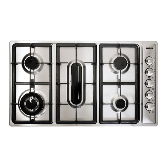
- Page 2 DESCRIPTION OF THE HOT PLATES Natural U-LPG Ultra rapid gas burner/Wok 15.0 MJ 15.0* MJ Semi-rapid gas burner 7.3 MJ 6.9 MJ Auxiliary gas burners 4.0 MJ 3.8 MJ Fish gas burner 12.0 MJ 11.5 MJ Right trivet 2 burners Left trivet 2 burners Central fish trivet 10 Burner 1 control knob...
- Page 3 table and fig. 2). 1) BURNERS - When the pan comes to the boil, set the knob to the A diagram is screen-printed above each knob on reduced rate position (small flame fig. 1). the front panel. This diagram indicates to which - Always place a lid on the pans.
- Page 4 Notes: Use of a gas cooking appliance produces heat and moisture in the room in which it is installed. The room must therefore be well ventilated by keeping the natural air vents clear (fig. 3) and by activating the mechanical aeration device (suction hood or electric fan fig. 4 and fig. 5). Intensive and lengthy use of the appliance may require additional ventilation.
-
Page 5: Care And Maintenance
CLEANING IMPORTANT: CARE & MAINTENANCE To optimise the appearance and up keep of Always disconnect the appliance from the gas stainless steel: and electricity mains before carrying out any 1) ALWAYS keep stainless steel out of contact from cleaning operation. acid/acid based solvent (liquid or vapour form). -
Page 6: Installation
INSTALLATION TECHNICAL INFORMATION FOR THE from the edge of any hob burner must be a suitable INSTALLER non-combustible material for a height of 150 mm for the entire length of the hob. Any combustible This appliance shall be installed only by construction above the hotplate must be at least authorised personnel and in accordance with 600 mm above the construction above the top of... -
Page 7: Gas Connection
INSTALLATION The transition piece on the supply side of the 5) GAS CONNECTION regulator must be provided by the installer. The gas connection is located in the rear and on the Liquified Petroleum Gas underside of the appliance 100 mm from the right In a LPG installation the gas regulation is made at hand side. - Page 8 ADJUSTMENTS Always disconnect the appliance from the 7) TAPS electricity main before making any adjustments. Our taps are suitable for all gas, they are male All seals must be replaced by the technician at conical type. the end of any adjustments or regulations. “Reduced rate”...
- Page 9 PROCEDURE LPG CONVERSION PROCEDURE Appliance models: Gas stainless steel hotplate Appliance models: Gas stainless steel hotplate models: models: BCG95 5 Burners BCG95 5 Burners 1. Remove each burner cap and burner skirt. 1. Remove each burner cap and burner skirt.
-
Page 10: Replacing The Injectors
CONVERSIONS affix the label corresponding to the new gas 10) REPLACING THE INJECTORS regulation on the appliance instead of the already The burners can be adapted to different types of gas existing one. This label is supplied in the packet by installing injectors suited to the type of gas containing the spare injectors. - Page 11 SERVICING Always turn off the electrical ignition before Greasing the taps (see fig. 17 - 18) proceeding with any servicing operation. If a tap becomes stiff to operate, it must be Servicing should be carried out only by immediately greased in compliance with the authorised personnel.
- Page 12 SERVICING CABLE TYPES AND SECTIONS TYPE OF TYPE OF SINGLE - PHASE HOT PLATE CABLE POWER SUPPLY Gas hot plate H05 RR - F Section 3 X 0.75 mm ATTENTION!!! If the power supply cable is replaced, the installer should leave the ground wire longer than the phase conductors (fig.
Need help?
Do you have a question about the BCG95 and is the answer not in the manual?
Questions and answers