Sign In
Upload
Download
Table of Contents
Contents
Add to my manuals
Delete from my manuals
Share
URL of this page:
HTML Link:
Bookmark this page
Add
Manual will be automatically added to "My Manuals"
Print this page
×
Bookmark added
×
Added to my manuals
Manuals
Brands
Partner Manuals
Touch terminals
A4-1-A
Service manual
Partner A4-1-A Service Manual
Hide thumbs
1
2
3
4
5
6
Table Of Contents
7
8
9
10
11
12
13
14
15
16
17
18
19
20
21
22
23
24
25
26
27
28
29
30
31
32
33
34
35
36
37
38
39
40
41
42
43
44
45
46
47
48
49
50
51
52
53
54
55
56
57
58
59
60
61
62
63
64
65
66
67
68
69
70
71
page
of
71
Go
/
71
Contents
Table of Contents
Bookmarks
Table of Contents
Regulatory Notices
Safety Information
Contact Information
About this Manual
Copyright and Trademark
Table of Contents
Chapter 1 Getting Started
Unpacking
Identifying Components
Connector Pin Define
Mainboard Jumper
Mainboard Connectors
Chapter 2 BIOS Setup
About the BIOS Setup Utility
Entering the Setup Utility
Using BIOS
BIOS Navigation Keys
Main Screen
Advanced Settings
Chipset Settings
Security Settings
Boot Settings
Save & Exit
Chapter 3 Installing Drivers and Software
Intel Chipset Driver
LAN Driver
Audio Driver
Serial IO Driver
Graphics Driver
Chapter 4 Locating the Problem
General Checkout Guidelines
Cash Drawer Checkout
LCD Symptoms
Touch Screen Symptoms
Power Symptoms
Network Symptoms
USB Symptoms
Peripheral-Device Symptoms
Boot Symptoms
Chapter 5 Replacing Field Replaceable Units (Frus)
Panel
Panel
Msr Pcba
Power Button and LED PCBA
Speaker
VGA Port
LVDS Cable
I/O Shield
Mainboard
Appendix A Specification
Advertisement
Quick Links
1
Identifying Components
2
Touch Screen Symptoms
Download this manual
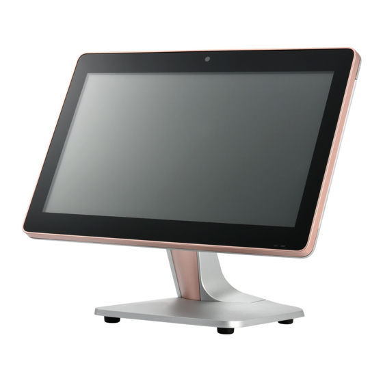
POS Terminal
A4-1-A
A5-1-A
A7-1-A
Service Manual
Table of
Contents
Previous
Page
Next
Page
1
2
3
4
5
Advertisement
Table of Contents
Need help?
Do you have a question about the A4-1-A and is the answer not in the manual?
Ask a question
Questions and answers
Subscribe to Our Youtube Channel
Related Manuals for Partner A4-1-A
Touch terminals Partner A4-1-K Service Manual
Pos terminal (63 pages)
Touch terminals Partner A5-1-K Service Manual
Pos terminal (63 pages)
Touch terminals Partner A7-1-K Service Manual
Pos terminal (63 pages)
Touch terminals Partner A5-1-A Service Manual
(71 pages)
Touch terminals Partner A4-1-E Service Manual
Pos terminal (69 pages)
Touch terminals Partner WT-100 Service Manual
Pos terminal (70 pages)
Touch terminals Partner SP-850 Service Manual
Pos terminal (75 pages)
Touch terminals Partner SP-600-A Service Manual
Pos (80 pages)
Touch terminals Partner PT-6200 User Manual
(50 pages)
Touch terminals Partner PT-6212-EB Service Manual
All in one pos terminal (78 pages)
Touch terminals Partner SP-1060 Service Manual
Pos terminal (73 pages)
Touch terminals Partner SP-550 Service Manual
Pos terminal (61 pages)
Touch terminals Partner SP-5514 Quick Start Manual
(2 pages)
Touch terminals Partner SP-820 Service Manual
Pos terminal (80 pages)
Touch terminals Partner SP-800 Service Manual
(70 pages)
Touch terminals Partner SP-1030 Service Manual
Pos terminal (80 pages)
This manual is also suitable for:
A5-1-a
A7-1-a
Table of Contents
Print
Rename the bookmark
Delete bookmark?
Delete from my manuals?
Login
Sign In
OR
Sign in with Facebook
Sign in with Google
Upload manual
Upload from disk
Upload from URL


Need help?
Do you have a question about the A4-1-A and is the answer not in the manual?
Questions and answers