Advertisement
Quick Links
Advertisement
Chapters

Related Manuals for Edgewater Networks 188 Center Console 2014


Summary of Contents for Edgewater Networks 188 Center Console 2014
- Page 1 188CC Center Console OWNER ASSISTANCE MANUAL Revised 2014...
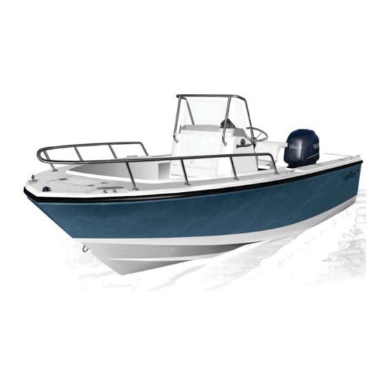
- Page 2 188CC SPECIFICATIONS LENGTH: 18’8” (5.7m) BEAM: 7’9” (2.3m) DRAFT (boat only): 13” (33.5cm) BOAT WEIGHT: 2050lbs (930kg) WEIGHT CAPACITY: 2100lbs (953kg) PERSON CAPACITY: PERSON WEIGHT: 1155lbs (523.9kg) FUEL CAPACITY: 43gal (162.77L) TRANSOM HEIGHT: S-25 MAX POWER: 150hp (115kw) COCKPIT DEPTH: 24”...
- Page 3 Dear EdgeWater 188CC Owner: Congratulations on purchasing one of the finest small boats ever built. It has been constructed with care from the finest available materials. At EdgeWater we take great pride in the quality and craftsmanship that goes into each boat, large or small. We believe you’ll have many years of enjoyment from your new EdgeWater and thank you for entrusting your leisure time to one of our fine products.
- Page 4 Service Information Please fill out the information below completely. It will help us in assisting you in the event your EdgeWater needs service. Customer Name Address City State Phone Cell Business E-mail Address Dealer Name Address City State Phone Purchase Date Engine Make/Model Delivery Date Engine Serial #...
-
Page 5: Table Of Contents
Table of Contents Chapter 1 General Information ..............6 1.1 General ..........................6 1.2 Owner / Operator Responsibilities ..................6 Chapter 2 Helm Control Systems..............7 2.1 General ..........................7 2.2 Steering System........................7 2.3 Engine Throttle and Shift Controls ..................7 Chapter 3 Propulsion System..............8 3.1 General .......................... - Page 6 8.3 Suggested Safety Equipment – Offshore................19 Chapter 9 Safe Operation..............19 9.1 Pre-Cruise Check List ......................19 9.2 Basic Rules of the Road ....................20 9.3 Safe Operation........................21 9.4 Towing or Being Towed ..................... 22 9.5 Stopping the Boat ......................22 9.6 Docking ..........................22 9.7 After Operation .........................23 9.8 Trailering Your Boat ......................23 9.9 Launching Your Boat ......................24...
-
Page 7: Chapter 1 General Information
1/General Information 1.1 General The EdgeWater 188CC is a semi-custom fishing vessel designed to be powered by a single outboard engine. 1.2 Owner / Operator Responsibilities Registration Registering your boat is important to you. Federal Law requires that all powered, undocumented vessels be registered in their state of principal use. -
Page 8: Chapter 2 Helm Control Systems
2/Helm Control Systems 2.1 General The helm station is the control center for the boat. The main control systems are the engine throttle and shift controls, the steering system, and the trim tab controls. These provide the operator the ability to control speed, direction, boat trim, and attitude. Each manufacturer provides manuals on the operation and use of their systems. -
Page 9: Chapter 3 Propulsion System
Do not bring the throttle back abruptly to stop the boat unless it is an emergency. Allow time for the engine RPM to come down to idle before shifting to reverse or severe gearbox damage could occur. PLEASE REFER TO YOUR ENGINE OWNER’S MANUAL FOR FURTHER OPERATIONAL PROCUDURES FOR YOUR OUTBOARD. -
Page 10: Engine Cooling System
Do not paint your outboard’s lower unit with paints designed for boat hulls. Some can cause severe damage to your engine. Check with your engine manufacturer to get their recommendation. Do not attempt control adjustments unless you are very familiar with their function, operation and adjustment. -
Page 11: Engine Power Tilt And Trim
3.4 Engine Power Tilt and Trim The power tilt and trim system on your outboard provides the ability to optimize the running angle of your EdgeWater 188CC to allow for load and sea conditions. Moving the outboard lower unit toward the transom is generally referred to as trimming “in”, while moving the outboard lower unit away from the transom is referred to trimming “out”. - Page 12 Temperature Gauge This is designed to monitor the operating temperature of your engine’s cooling system. A sudden rise from the normal should be investigated to determine if there is an obstruction in the cooling system. Water Pressure Gauge This gauge measures pressure in the engine cooling system. If the pressure changes from the norm it could indicate a complete or partial blockage in the system or a water pump problem.
-
Page 13: Chapter 4 Fuel System
Instrument Maintenance Your instrument faces should be periodically cleaned to keep them free of salt and atmospheric debris. The ignition switches should be periodically sprayed with a contact cleaner/lubricant to keep them free of corrosion and dirt. 4/ Fuel System 4.1 General All fuel systems and components on your EdgeWater 188CC have been checked and each fuel tank has been pressure tested. -
Page 14: Fuel System Maintenance
Begin fueling. · When the tank is full, stop fueling. · Remove the fuel nozzle. · Install the fuel cap. · Check the area for fuel odors. · Warning: If fuel odors are detected, do not start the engine! Check to make certain there are no leaks or system problems before starting the engine. -
Page 15: Electrical System Maintenance
are each protected by a circuit breaker. Check that the requirement of any device you install does not exceed the rating of the circuit breaker being used. When equipped with dual batteries the boat will have a battery selector switch which provides isolation for each battery and also provides the ability to have a back-up in case of a dead or weak battery. -
Page 16: High Pressure Washdown
6.3 High Pressure Washdown The washdown system is comprised of a diaphragm pump mounted on the hull inside the helms’ console and a washdown fitting to attach a hose. The washdown switch on the control panel controls the pump. The diaphragm pump is fed through the same thru hull and high speed pickup as the livewell pump. -
Page 17: Drain System Maintenance
7.2 Drain System Maintenance Essential tasks must be done periodically to maintain your boat’s ability to drain in adverse conditions. Clean cockpit drains to remove debris or other foreign objects which could prevent boat from draining properly. Check bilge area for debris and foreign material, which can cause automatic switches to malfunction. -
Page 18: T-Top Drain (Optional T-Top)
7.6 T-Top Drain (optional T-Top) There are small holes drilled into the bottom of the T-top to facilitate the removal of any water that might inadvertently get into the structure. These should be periodically checked, especially during freezing weather, as trapped water could freeze, expand, and damage the t-top. 8/Safety Equipment 8.1 Required Safety Equipment Contact the U.S. -
Page 19: Suggested Safety Equipment - Inshore
Safety Hotline at 1-800-368-5647, or 1-202-267-1070. You should, as part of routine boat maintenance; check to make sure your extinguisher is still operable. Never discharge your fire extinguisher to see if it still works. This will cause it to lose pressure. -
Page 20: Chapter 9 Safe Operation
9/Safe Operation 9.1 Pre-Cruise Check List Check provisions. Make sure you have plenty of water in the event you have a problem and are delayed. Check the weather forecast. Avoid sea conditions that are beyond the experience of yourself and your crew. Do you have the correct safety gear aboard and is it in good working order? Make sure all fire extinguishers are in good working order. -
Page 21: Basic Rules Of The Road
Never operate the boat while under the influence of alcohol! Make sure someone else on-board knows how to operate the boat in the event you are injured and unable to operate the boat. If you are operating the boat for the first time, make sure you follow the engine manufacturer’s break-in recommendations. -
Page 22: Safe Operation
Daymark Can Buoy Lighted Buoy (green light) Lateral Aids as seen from Seaward (starboard side red) Lighted Buoy Nun Buoy Daymark (red light) 9.3 Safe Operation Getting Underway After clearing the dock, make sure the power trim (if so equipped) is trimmed down. (This will bring the boat up on plane more quickly and easily.) Give the engine sufficient throttle to bring it to plane briskly, then back down to the cruising speed of your choice, based on the sea conditions and your planned activity. -
Page 23: Towing Or Being Towed
While underway keep a constant vigil for other craft that may be approaching, the gauges on your boat, location of passengers and the general sound and feel of your craft. Often, a change in the way the engine sounds or the boat feels will presage a problem. Your early attention may prevent a more serious problem. -
Page 24: After Operation
Perform docking at idle or no wake speeds. Always try to come into wind or current, whichever is stronger. This allows you to use the natural forces on your boat to act as a natural brake. The skipper is free to use the boat’s power to control speed and direction. The approach to the dock should be at roughly a 45 angle, when possible. -
Page 25: Launching Your Boat
If you are new to trailering your boat, it is best to practice before actually getting in a situation where you are not sure of your ability. If possible use a trailer without a boat to practice with as you can see the trailer’s movement without the boat. Also, your vision will not be impaired by the boat’s presence. -
Page 26: Chapter 10 Routine Maintenance
Drive the boat onto the middle of the trailer. This is assuming it is a trailer designed for drive on. Speed should not be over one or two knots. Fast enough to maintain steerage but slow enough to be easily controlled. Once the boat has touched the trailer, a little forward throttle should secure the boat on the trailer and allow you to put the engine in neutral and have the winch line attached to the bow eye. -
Page 27: Engine
Use a good metal polish and protect with wax. This should be done every couple of months or as soon as you notice any finish deterioration. Plexiglas Do not use products with ammonia on your Plexiglas windscreen. It can mar the surface and reduce its transparency. -
Page 28: Chapter 11 Exterior Equipment
11/ Exterior Equipment 11.1 Anchor Locker The anchor locker on your new EdgeWater 188CC has been designed for a danforth style anchor. On the 188CC the anchor locker is located forward on the centerline. Before using the anchor for an extended period or overnight, make sure the free end of the anchor line is shackled to the boat’s forward eye. -
Page 29: Hull
Change the engine lower unit lubricant. This will remove contaminants that may have built up throughout the boating season. This is also a good time to check for lower unit seal problems. If there is a leak, have it repaired by your dealer. Remove the propeller and grease the propeller shaft. -
Page 30: Appendix
Appendix 188CC... - Page 32 Hydraulic Steering System...
- Page 33 SUGGESTED UNDERWAY OCCUPANT POSITIONS 188 CC WEIGHT SHOULD BE EVENLY DISTRIBUTED...
- Page 38 BAYSTAR | SEASTAR | HYNAUTIC H Y D R A U L I C S T E E R I N G S E L E C T I O N G U I D E 2 0 0 8 M A R I N E...
- Page 39 Boating safety is everyone's responsibility. As a boater, you are responsible for having all required safety equipment, for operating your boat safety and for ensuring the safety of those on board your vessel as well as those sharing the waterways. Boaters exercising courtesy and common sense will not create a hazard, threat, stress or an irritant to themselves, to others, to the environment, or to wildlife.
- Page 40 TABLE OF CONTENTS The BayStar & SeaStar Hydraulic Steering Systems. BayStar Outboard Steering System. BayStar Compact Application Guide SeaStar Power Assist SeaStar Outboard Steering Systems. Front Mount Steering System SeaStar Pro Steering Outboard— Catamaran 3-12 Side Mount Steering System 3-13 Splashwell Mount Steering System 3-16 SeaStar Sterndrive Systems.
- Page 41 BayStar and SeaStar Hydraulic Steering Systems The BayStar Hydraulic Steering System is designed to add safety, reliability and comfort to single station outboard powered boats to a maximum 150HP (Total). The SeaStar Hydraulic Steering System is designed to provide that extra margin of muscle when needed. The SeaStar system easily handles Outboards, Sterndrive and Inboard boats.
- Page 42 Teleflex Hydraulic Steering Our manual hydraulic steering systems are simple and efficient. The basic system consists of three main components; 1) the helm pump, 2) the cylinder, and 3) the hose or tubing required to connect the cylinder to the helm pump. These basic components are necessary in all applications.
- Page 43 The objective is to match the steering system to the requirements Selecting the System of the vessel. This depends on four things; 1) hull type (ie: planing or displacement), 2) type of propulsion system in the vessel (ie: inboard, outboard, sterndrive, etc.), 3) the number of engines or rudders, 4) the total power of the engines (ie: Horsepower).
- Page 44 System Selection Worksheet How can we help? OUTBOARD–Single up to 150HP UNDER 55mph Most economical system to meet my steering needs ..Page 1-1 We have provided the following Economical to meet my needs, PLUS less effort at check list to assist you in choosing the steering wheel than above...........Page 3-1, 3-9 your Hydraulic Steering System.
- Page 45 Selection Guide...
- Page 46 CHAPTER OUTBOARD STEERING BayStar ™ ˙hydraulic steering is brought to you by the manufacturers of SeaStar ® , the most trusted name in pleasure boat steering. BayStar allows you to install all of the safety, reliability and comfort of hydraulic steering onto your boats rated up to MAX.
- Page 47 OUTBOARD–FRONT MOUNT Three easy steps to select 1) Check helm dimension. Both the Standard and Tilt helms require a 3" (76mm) cut-out hole in the dash. your BayStar System: STANDARD HELM PART# HH4314 5/8" NF THREAD 1/4" NPT FILL PORT 3/4"...
- Page 48 OUTBOARD–FRONT MOUNT 2) Check the BayStar cylinder dimensions through the full trim/tilt range of the engine. IS THE SPLASHWELL WIDE ENOUGH? The HC4645H/47H/48H /58H require a 21" (534mm) Splashwell width. BAYSTAR CYLINDER PART# HC4645H/47H/48/H58H 2.625" (67mm) 21" (534mm) 3) Is there enough room in the splashwell for full engine tilt? Find the dimensions (A, B &...
- Page 49 OUTBOARD–FRONT MOUNT BayStar Steering Kits BayStar Steering kits come complete with everything needed for an install, (some engines require spacer kits and/or cylinder plate change, PID# HK4200A, HK4230A see application chart on page 1-5) the compact cylinder does not require the engine manufacturer drag link for connection. For your convenience two lengths of 20' cut to fit tubing are supplied with the HK4200A and two lengths of 30' cut to fit tubing are supplied with the HK4230A kit.
-
Page 50: Baystar Compact Application Guide
BayStar Outboard Compact OUTBOARD–FRONT MOUNT Application Guide (BayStar Compact Cylinders HC4645/47/48/58) YEAR MODEL CYLINDER NOTES FORCE 1985–DATE 90–150 HP HC4645H HONDA 1992–DATE 30–90 HP HC4645H 1998–DATE 115–130 HP HC4647H 2001–DATE 150 HP HC4645H 2003–DATE BF135 HP HC4645H JOHNSON/ 1977–1989 65–150 HP HC4648H EVINRUDE 1991–DATE... - Page 51 Selection Guide...
-
Page 52: Seastar Power Assist
CHAPTER POWER ASSIST SeaStar Power Assist Pilot shown, available Summer, 2008. The Marine Industry is continually introducing heavier outboard engines, higher horse power engines, more aggressive propellers, bigger/faster boats... Boat operators are asking for increased comfort and lighter steering loads... These were the driving forces behind the design of SeaStar and SeaStar PRO Power Assist. - Page 53 POWER ASSIST How the System Works SeaStar P/A (Power Assist) steering uses an electronically controlled hydraulic pump to provide "Power" for your SeaStar Hydraulic Steering system. The SeaStar P/A system is comprised of two circuits: a hand operated manual system, which is the control element, and a hydraulic power pump, which is the working element.
- Page 54 POWER ASSIST SeaStar P/A The P/A is designed for use in recreational marine applications in Compatibility Chart conjunction with SeaStar Hydraulic Steering. Optimal performance will be obtained when used with SeaStar 1.4, 1.7 and 2.0 cu in (1000psi) helm pumps, or, 2.0 cu in (1500 psi) SeaStar P/A PRO Hydraulic Steering. NOTICE SeaStar nylon tube may ONLY be used for the compensating line.
- Page 55 Selection Guide...
- Page 56 CHAPTER OUTBOARD STEERING SeaStar Outboard Hydraulic Steering offers three models of steering cylinders to suit most applications. The standard and most commonly used model is the Front Mount Steering Cylinder HC5345/47/48/58. The Side Mount Cylinder HC5370 and the Splashwell Mount Cylinder HC5380.
- Page 57 SEASTAR FRONT MOUNT OUTBOARD STEERING SYSTEM Part# HC5345, HC5347, HC5348, HC5358 • Independent engine tilt for twin engine installations. Features • Easy steering. • 5 turns lock to lock steering response. Applications • General purpose system. • Single and multiple engine capability. •...
- Page 58 Order Guide OUTBOARD–FRONT MOUNT NOTICE Front Mount Cylinder part# HC5345 is included in the SeaStar Outboard Steering Kits HK6400/63XX and HK7400/73XX. If your engine requires the use of a cylinder other than the HC5345 (see application guides on pages 3-5 through 3-6) you will need to purchase the individual components (helm, cylinder, hoses, etc.) separately.
- Page 59 300HP + Outboard Installation OUTBOARD–FRONT MOUNT Recommendations With the introduction of heavier, higher horsepower engines producing more torque, Teleflex Marine has updated its recommendations across various applications (single and multiple engines, different hull types, etc.) Please read carefully to ensure that your current steering system provides the best comfort versus performance available.
-
Page 60: Seastar Outboard Steering Systems
Single Engine Application Guide OUTBOARD–FRONT MOUNT Prior to selecting a cylinder from this application guide, please refer to page 3-4 to ensure that you are selecting the correct cylinder for your engine/boat. NOTICE Is your Splashwell wide enough? Check page 3-11 for space requirements. YEAR MODEL NOTES... - Page 61 Twin Engine Application Guide OUTBOARD–FRONT MOUNT Prior to selecting a cylinder from this application guide, please refer to page 3-4 to ensure that you are selecting the correct cylinder for your engine/boat. NOTICE Is your Splashwell wide enough? Check page 3-11 for space requirements. TIE BAR KITS YEAR MODEL...
- Page 62 Triple Engine Application Guide OUTBOARD–FRONT MOUNT Prior to selecting a cylinder from this application guide, please refer to page 3-4 to ensure that you are selecting the correct cylinder for your engine/boat. WARNING Use of incorrect components on a high speed/ performance boat, may lead to bending and breaking of components resulting in steering failure causing property damage and/or personal injury.
- Page 63 Tournament Series Tiebar Cylinders OUTBOARD–FRONT MOUNT With the power and speed increasing for performance orientated fishing boats, Teleflex Marine felt it prudent to set up a dedicated application for these types of boats. If your application calls for a dual or triple Outboard Engine configuration, is capable of speeds exceeding 55mph and runs in open water, please refer to the Tournament NOTICE...
-
Page 64: Seastar Pro Steering
SeaStar Pro Steering Systems OUTBOARD–FRONT MOUNT SeaStar PRO Outboard Steering systems are suited for all those critical high speed, single powered outboard boats, like Bass, Flats, combo Race/Ski and other performance orientated boats capable of speeds in excess of 65mph. Before ordering it is necessary to determine the proper cylinder and helm pump for your application. - Page 65 SeaStar Pro Application Guide OUTBOARD–FRONT MOUNT NOTICE Is your Splashwell wide enough? Check page 3-11 for space requirements. YEAR MODEL NOTES FORCE 1985-DATE 90-150HP HC6345 HONDA 1996-DATE 150-300HP HC6345 JOHNSON/ 1977-1990 150-300HP Contact Teleflex EVINRUDE 2002-DATE 150-250HP 4-Stroke HC6345 2003-DATE 150-300HP ETech HC6345 2005-DATE...
- Page 66 Cylinder Installation and OUTBOARD–FRONT MOUNT General Dimensions WARNING Operational interference of the steering cylinder/cylinder fittings and jackplates/transom/splashwell can occur under certain conditions. Check installation thoroughly throughout the full range of Motor Tilt, Jack Height and Trim before making final installation. If interference does occur, contact: Teleflex Canada Limited Partnership for additional information/options.
-
Page 67: Outboard-Catamaran
Outboard–Catamaran OUTBOARD–FRONT MOUNT ENGINE MAXIMUM CYLINDER RECOMMENDED NO. OF STEERING Horsepower Limitations CONFIGURATIONS HORSEPOWER HELM PUMP WHEEL TURNS NON COUNTER-ROTATING UP TO 450HP HC5343 HH5271 HC5374 HH5272 COUNTER-ROTATING UP TO 600HP HC5343 HH5271 HC5374 HH5272 To establish whether or not this cylinder is suitable for your application, the following points should be considered: 1. - Page 68 SEASTAR SIDE MOUNT OUTBOARD STEERING SYSTEM Part# HC5370 Features • Ease of installation. • Alternative to Front Mount Cylinder. • Unbalanced cylinder with 4.8/5.7 turns lock to lock. • Suitable for installation in shallow splashwells. • Suitable for use on engines fitted with power steering. Applications •...
- Page 69 Order Guide OUTBOARD–SIDE MOUNT DESCRIPTION MODEL PART REF. ENGINE/ CYLINDER NUMBER PAGE # CONFIGURATION SINGLE ENGINE CYLINDER SIDE MOUNT HC5370 HELM * SEASTAR I- STANDARD HH5271 (SINGLE CYLINDER) HOSE KIT OUTBOARD HOSE HO51_ _ 10-2 APPLICATIONS UP TO 300 HP MAX SEASTAR OIL HA5430 11-1...
- Page 70 General Dimensions OUTBOARD–SIDE MOUNT Tie Bar for Side Mount Cylinders Part# HO5009 ENGINE CENTRE DISTANCE MAXIMUM: 36" (914mm) MINIMUM: 26" (660mm) PART# HC5370 0.75" (19mm) AT 3/8" COMPRESSION FITTING FULL RETRACTION 1.5" DIA (38mm) 1.5" (38mm) 9" (229mm) AT 13" (330mm) FULL EXTENSION LINK ARM SUPPLIED BY ENGINE MANUFACTURER...
- Page 71 SEASTAR SPLASHWELL MOUNT OUTBOARD STEERING SYSTEM Part# HC5380 NOTICE Not for use with SeaStar Pro Helms. Features • Light duty alternative to front & side mount cylinders. • Unbalanced cylinder with 5.5/6.5 turns lock to lock. • Fits engines with/without support (steering) tube. Applications •...
- Page 72 Order Guide OUTBOARD–SPLASHWELL MOUNT The splashwell mount cylinder (part no. HC5380) can be used on all engines complying with ABYC P17/NMEA/BIA standards provided they have a threaded attachment hole (3/8" – 24 UNF thread) in the steering arm. Not suitable for use on engines fitted with factory power steering.
- Page 73 General Dimensions OUTBOARD–SPLASHWELL MOUNT Mounting Configuration Tie Bar Kit# HO5010 36" (914mm) MAXIMUM ENGINE CENTRE DISTANCE 26" (660mm) MINIMUM ENGINE CENTRE DISTANCE PART# HC5380 NOTICE DO NOT use a PRO Helm pump with this, or any other unbalanced steering cylinder. Selection Guide 3-18...
- Page 74 CHAPTER STERNDRIVE STEERING Features • Easy installation. • Simple autopilot interface. • Simple multiple steering station connection. Applications • Fits most power and non-power assist sterndrives. • Single and multiple drives. How to select a steering 1) From the order guide on page 4-2 select the drive configuration based on the number of drives.
- Page 75 Order Guide STERNDRIVE STEERING SYSTEM COMPONENT MODEL PART PAGE CONFIGURATION DESCRIPTION REF # SINGLE & DUAL STERNDRIVE CYLINDER SEE APPLICATION GUIDE HELM * SEASTAR I STANDARD (SEE NOTE 1) HH5271 (For dual sterndrive applications use ** SEASTAR II-STANDARD (SEE NOTE 2) HH5272 engine manufactures supplied tie bar.) SEASTAR OIL...
- Page 76 Application Guide STERNDRIVE STEERING ENGINE STEERING ENGINE/DRIVE YEAR CYLINDER DESCRIPTION NUMBER TURNS NOTES MANUFACTURER CONFIGURATION DESCRIPTION LOCK TO LOCK MODEL No. PART No. SEASTAR I SEASTAR II HELM HELM NON POWER TO DATE BA125-8EMV HC5330 ASSIST POWER ASSIST TO DATE 125-8EM HC5328 4.9/5.8...
- Page 77 General Dimensions STERNDRIVE STEERING HC5332 135-7EM 12.08" (306.86 mm) 5" (127mm) REQUIRED FOR 0.25" UNRESTRICTED MOUNTING 8.85" (224.79 mm) 12.5" (317.5 mm) (6.35 mm) NOTICE If engine outdrive is NOT equipped with a torque tab on the underside of the lower leg, one must be installed to 0.625"...
- Page 78 General Dimensions STERNDRIVE STEERING HC5329 125-8VEM NOTICE DO NOT use a PRO Helm pump with this, or any other unbalanced steering cylinder. HC5330 BA125-8EMV SEASTAR and BAYSTAR Hydraulic Steering Systems...
- Page 79 General Dimensions STERNDRIVE STEERING HC5331 92-VPS NOTICE DO NOT use a PRO Helm pump with this, or any other unbalanced steering cylinder. HC5314 BA150-7ATM Selection Guide...
- Page 80 STERNDRIVE STEERING Performance I/O and The K-5-B cylinder was designed for inboard/outboard boats requiring external cylinders of substantial size and strength. The K-5 cylinders Outboard Cylinders are nickel plated for aesthetics and protection against the elements. This cylinder does not include the wing plates or hardware required for mounting to the outdrive.
- Page 81 Selection Guide...
- Page 82 CHAPTER INBOARD STEERING Features • Regular duty aluminum cylinders. • Heavy duty brass cylinders. • Easy installation for single and dual rudder vessels. • Cylinders supplied with bleeder fittings. • Two axis articulation. • Easy autopilot interface. Four steps to select a 1) From the Application Guide on page 5-2 select the System Number appropriate for the vessel based on;...
- Page 83 Application Guide INBOARD STEERING NOTICE Want automotive type steering? Refer to page 2-1 for Power Assist Details. BOAT LENGTH PLANING HULL DISPLACEMENT HULL SAIL UP TO SINGLE ENGINE TWIN ENGINE SINGLE ENGINE TWIN ENGINE SINGLE ENGINE PLEASURE WORK PLEASURE WORK PLEASURE WORK PLEASURE...
- Page 84 General Dimensions–SeaStar INBOARD STEERING ATM CYLINDERS (ALUMINUM): HC5312-2/ HC5313/ HC5314 CYLINDER DIMENSIONS SPECIFIC TO MODEL CYLINDER PART BODY SHAFT MODEL DIAMETER DIAMETER BA125-7ATM HC5312 1.38" (35mm) 0.50" (12.7mm) TM CYLINDERS (BRASS): HC5318/ HC5319/HC5369 BA135-7ATM HC5313 1.50" (38mm) 0.63" (15.9mm) BA150-7ATM HC5314 1.75"...
- Page 85 General Dimensions–Hynautic INBOARD STEERING The K-18 and K-19 balanced cylinders are double rod ended, each Universal Mount Cylinders end held in place with internal wire ties. Every cylinder is equipped K-18/K-19 with a swivel joint at each end. One provides for a fixed mount attachment point at the end of the housing to protect the moving rod.
- Page 86 INBOARD STEERING Fixed Mount and Pivot These Brass cylinders are for larger boats up to approximately 70 ft. Tubes, ends, and external rods are brass: cylinder rods are 17-4 Mount models: stainless steel: mounts are manganese bronze. There are two K-22, K-27 and K-31 different types of mounting packages for Brass cylinders: fixed mount and pivot mount.
- Page 87 INBOARD STEERING Large I/B Cylinders The K-8 and K-9 cylinders are double rod end, tie rod constructed hydraulic cylinders. Each has a universal mount, which allows two K-8/K-9 planes of pivot freedom. Each cylinder is equipped with a stainless steel ball joint. Porting is through two 1/4" NPT ports at each end of the cylinder.
-
Page 88: Hynautic 3-Line Inboard Steering
CHAPTER HYNAUTIC 3-LINE INBOARD STEERING Introduction SeaStar offers rugged 3-line Hynautic Heavy Duty steering systems for most work and pleasure vessels up to 70 feet. Heavy Duty helms combine one or two bi-directional axial piston pumps with pilot check and make-up check valving. The result is a unit which prevents rudder feedback, is very efficient (even at low RPM), and is immediately adaptable to multi-station use. - Page 89 3-LINE INBOARD STEERING Components H-21 .........Hynautic 2.75 cu. in. helm (1" straight shaft) H-25 ......Hynautic 2.75 cu. in. helm (3/4" tapered shaft) H-42 ........Hynautic 4.0 cu. in. helm (1" straight shaft) H-42-02 ......Hynautic 4.0 cu. in. helm (3/4" tapered shaft) H-41 ........Hynautic 5.5 cu.
-
Page 90: Application Guide
Hynautic 3-Line Inboard Steering 3-LINE INBOARD STEERING Application Guide TUBING DIAMETER WHEEL CYLINDER CYL. TO FARTHEST HELM MAX VESSEL SIZE HELM PUMP TURNS MODEL <40’ >40’ HPor AREA Planing Hulls: 35–50’ (11–15m) H-21 or H-25 HC5350 or HC5356 1/2" 5/8" 450 HP 40–50’... - Page 91 3-LINE INBOARD STEERING Helm Options Four helms are offered in 3 displacements, as noted in the chart at right. The H-21 helm has a 1" straight wheel shaft; H-25 has a 3/4" tapered shaft. The H-42 and H-41 helms both have a 1" straight wheel shaft. HELM PART# DISPLACEMENT RANGE RELIEF VALVE SETTING...
- Page 92 3-LINE INBOARD STEERING Reservoir Part# R-06 4-7/8" (124mm) Capacity = 2 quarts. 9-1/2" (241mm) 13-5/8" (346mm) Relief Valve Part# MSV-21 Relief Pressure factory set to 950psi. 3-7/8" (98.5mm) 2-1/2" 1" (63.5mm) (25mm) SEASTAR and BAYSTAR Hydraulic Steering Systems...
-
Page 93: Hynautic Seal Kits
Hynautic Seal Kits SEAL KITS SEAL KIT# DESCRIPTION Helms HS-01 H-20 Series Helms, 1978 and earlier HS-02 H-20 and H-30 Series Helms, 1979 and later HS-03 H-40 Series Helms, 1978 and earlier HS-04 H-40 Series Helms, 1979 and later HS-05 H-50 Series Helms HS-06 H-60 Series Helms... -
Page 94: Crossover Hynautic To Seastar Steering
Crossover Hynautic to SeaStar CROSS OVER Steering To review Advisory Notices, please view on line at www.seastarsteering.com or contact Teleflex Canada Limited Partnership directly at 604-270-6899. HYNAUTIC REPLACED WITH ADVISORY Cylinders CYLINDER SEASTAR PART# NOTICE# K-51 HC5314HY 764626 K-1-B/C HC5369HY/HYC 764624 K-2-B/C HC5373HY/HYC... - Page 95 Syten Hydraulic Steering Replacing or upgrading from a Syten inboard steering system to SeaStar Components. (Obsolete). Helms: The Syten helm pump should be replaced with the current model SeaStar Helm Pump HH5271 and Back mount kit HA5418. This should be done at each helm station. NOTICE Tube: The 5/16 nylon tube and fittings are obsolete and must be The Syten components were produced...
- Page 96 CHAPTER POWER STEERING POWER STEERING POWER STEERING HELM OIL RESERVOIR DRIVEN PUMP OIL COOLER OIL FILTER CYLINDER Features: • Effortless steering from docking to top speed • Responsive steering 3-1/2, turns lock to lock (or to suit) • Automatic manual back up steering •...
- Page 97 POWER STEERING Cylinder Selection Guide: * All boats over 70' should have steering loads reviewed by factory. CYLINDER PART NUMBER DISPLACEMENT HULLS DISPLACEMENT HULLS PLANING HULLS (standard) (heavy duty) SINGLE 9" x 1 CYLINDER (HC5801-2) UP TO ....50' (15m) UP TO ....40' (12m) UP TO ....65' (20m) TWIN 9"...
-
Page 98: Hynautic Trim Tabs
CHAPTER HYNAUTIC TRIM TABS The effort required to keep large pleasure yachts and commercial Introduction boats trim and level is usually too great for most fiberglass nylon trim cylinders, even when used in multiple combinations. This is especially true when backing down hard. Based on an understanding of these forces, Hynautic offers a heavy duty brass trim cylinder powerful enough to move and maintain the position of even the largest trim planes. - Page 99 TRIM TABS TCS-1-01 TAB CYLINDER SYS, 24 VOLT: Order Guide Control switch 1 ea ............TC-03 Tab cyl. - cruiser 2 ea ............TK-01 NOTICE Power pump 2 ea ............TP-01 Manual 1 ea ............182037 Pressure and plate dimensional Hose - 2ft. 4 ea ............207402 requirements are to be calculated by your Naval Architect.
- Page 100 CHAPTER HELMS The SeaStar helm pump is the heart of the hydraulic steering system. SeaStar helm pumps are the product of many years of research and experience by the world's foremost builder of manual hydraulic steering systems. Our efforts have resulted in a design which represents the ultimate in efficiency, safety and reliability, yet is easy to install and maintain.
- Page 101 Features of SeaStar Helm Pumps HELMS Features 1 Helm rotor supported by three roller bearings. 2 Ball bearing piston race. 3 Field replaceable shaft seal. 4 1/4" NPT ports. 5 Built-in lock valve for positive rudder lock. 6 Patented bleed tubes. 7 Internal air pocket eliminates oil expansion overflow.
- Page 102 Accessories HELMS Backplate Kit (part # HA5418) a) Used to retrofit a new Seastar standard helm in the old 4.5" (115mm) diameter hole, or b) reduce the helm protrusion from the dash by the thickness STEERING WHEEL of the dash, or c) retrofit new SEASTAR standard helm into hole cutouts for mechanical and hydraulic steering as per chart.
- Page 103 SeaStar Helm – Order Guide HELMS SeaStar Standard Mount PART HELM DISPLACEMENT RELIEF VALVE SETTING NOTES NUMBER DESCRIPTION CU. IN./REV (CC/REV) PSI (BAR) HH5269 STANDARD MOUNT (23.0) 1000 (70) HH5271 STANDARD MOUNT (27.8) 1000 (70) HH5761 STANDARD MOUNT FULL FEEDBACK (27.8) 1000 (70)
- Page 104 SeaStar PRO Helm – Order Guide HELMS SeaStar PRO Standard Mount PART HELM DISPLACEMENT RELIEF VALVE SETTING NOTES NUMBER DESCRIPTION CU. IN./REV (CC/REV) (BAR) HH5779 STANDARD MOUNT (27.8) 1500 (103) HH5218 STD. MOUNT, COMMERCIAL (27.8) 1500 (103) 1, 3 HH5770 STANDARD MOUNT (33.0) 1500...
- Page 105 Standard/Rear Mount Helm HELMS Dimensions NOTICE ALL SeaStar helm pumps can be mounted horizontally to vertically and anywhere in between. In ALL cases the filler port must be in the uppermost position. STANDARD FRONT MOUNT HELM PUMPS 1/4" NC STUDS (4) 3/4"...
- Page 106 Tilt/Sport Tilt Helm Dimensions HELMS TRADITIONAL STYLE TILT HELM PUMPS OUTLINE OF STEERING WHEEL HUB INCLUDES FITTING WOODRUFF KEY CLEARANCE 6.81" (173mm) 3/4" STANDARD TAPER 4.92" (125mm) 2.67" FILLER 5.81" (148mm) (68mm) 5.15" (131mm) PLUG .88" (22mm) 3.60" (91mm) 2.75" (70mm) 5.28"...
- Page 107 Hynautic Helm Pumps HELMS SHAFT STYLE INTEGRAL Heavy Duty Helm Pump HELM DISPL DIA. & TYPE KEYWAY VALVING H-20 Series 20 Series H-21 2.75cu in 1 Straight 1/4" Square H-25 2.75cu in 3/4", 1"/ft Tapered #9 Woodruff H-26 2.00cu in 3/4", 1"/ft Tapered #9 Woodruff H-21...
- Page 108 CHAPTER HOSE, TUBING, FITTINGS, ACCESSORIES AND TOOLS All SeaStar Manual Hydraulic Fittings steering systems utilize the same style of fittings for all applications. These are 3/8" compression fittings which utilize a 9/16"– 24 extra fine thread. TYPICAL FITTING Tubing/Hose The tubing or hose requirements depend on the type of steering system being considered.
- Page 109 SEASTAR OUTBOARD HOSE WARNING SeaStar Outboard hoses are available in kit’s (includes two hoses) SeaStar PRO Helm systems ranging in length from 2’ – 30’. Hydraulic Hose must be protected require the use of SeaStar PRO from chaffing and any possible contact or interference with assembly (1500 psi) reinforced Kevlar screws or sharp edges of any type.
-
Page 110: Outboard Hose
OUTBOARD HOSE Each part number contains two hoses of equal length. Available SeaStar Hose Kits: How to order PART NUMBER KIT DESCRIPTION * HO51XX SeaStar Standard Outboard Hose Kit (2 hoses) * HO57XX SeaStar Pro Hose Kit (2 hoses) ** HO81XX SeaStar Bulkhead Hose Kit, Standard (2 hoses) ** HO82XX SeaStar Bulkhead Hose Kit, Pro(2 hoses) - Page 111 Single Station OUTBOARD HOSE Figure A: Figure B: Figure C: HC5345 HC5370 HC5380 Single Front Mount Cylinder Single Side Mount Cylinder Single Splashwell Mount Cylinder Note: cylinder body moves Note: cylinder body stationary Note: cylinder body stationary Figure D: Figure E: Figure F: HC5345 HC5370...
- Page 112 Additional Stations or Autopilot OUTBOARD HOSE Integration Additional Steering Station 1) Determine the location of the 2nd station or power pack. or Autopilot Power pack 2) Measure along the intended path of the hose routing from the upper helm pump to the 2nd station or autopilot power pack. 3) Round up the measurement to the next even digit.
-
Page 113: Inboard/Sterndrive Tubing
SEASTAR INBOARD/STERNDRIVE TUBING Two types of tubing materials are available for plumbing Inboards and Sterndrives. 1) SeaStar 3/8" outside diameter nylon tubing 2) 3/8" outside diameter copper refrigeration tubing Nylon Tubing SeaStar 3/8" outside diameter nylon tubing is recommended for; a) Inboard, b) Sterndrive, and c) Seadrive steering systems with SeaStar I (1.7 cubic inch/rev... - Page 114 Single Station TUBING 1) From the illustration which best suits your application note the number of lengths of tubing and fitting kits required. 2) Measure along the intended path of tube routing for each of the tubing runs. 3) Determine if 3/8" nylon tube can be used or if copper tubing is required based on lengths of tubing runs required.
-
Page 115: Additional Seastar Steering Station Or Autopilot Kit
ADDITIONAL SEASTAR STEERING STATION OR AUTOPILOT KIT 1) Refer to illustration Figure E. 2) Determine the location of the second station or autopilot power pack. 3) Measure along the path of the tube routing from the upper helm pump to the second station or autopilot power pack. Multiply this length by three for the amount of tubing required. - Page 116 FITTINGS FITTINGS All SeaStar Manual Hydraulic HF5518 HF5519 HF5520 Vertical Bleeder Tee Bleed Tee Horiz. Bleeder Tee (TM Cylinders) steering systems utilize (2 per kit) (2 per kit) (2 per kit) 45˚ FLARE the same style of fittings 3/8" TUBE 3/4"...
- Page 117 FITTING KITS HF5501 WARNING Application DO NOT cut SeaStar Fitting kit to add a 2nd station Outboard Hoses or autopilot to an outboard system. ITEM QUANTITY PART NO. DESCRIPTION PER KIT Tee Fitting 600603 1 End – 3/8" NPT (M) 1 End –...
- Page 118 FITTING KITS HF5502 Application Fitting kit to add a 2nd station or autopilot to an inboard or sterndrive system ITEM QUANTITY PART NO. DESCRIPTION PER KIT Tube Nut – 3/8" Dia. 280327 Connector Fitting 600602 3/8" Tube (M) – 1/4" NPT (M) Tee Fitting 600605 3 Ends –...
- Page 119 FITTING KITS HF5507 Application Kit to connect 3/8" diameter copper tubing to SeaStar cylinders (using 3/8" diameter nylon tubing) ITEM QUANTITY PART NO. DESCRIPTION PER KIT Tube Nut – 3/8" Dia. 280327 Connector Fitting 280929 3/8" Tube (M) – 3/8" Tube (M) Nylon Tubing 795628 3/8"...
- Page 120 FITTING KITS HF5512 3/4" bulkhead fitting kit Application: Single cylinder installations 2 Assemblies per kit ITEM QUANTITY PART NO. DESCRIPTION PER KIT Connector Fitting 286323 Street Elbow 600606 3/8" Tube (M) – 1/4" NPT(F) Washer 202224 191621 2 OF EACH ILLUSTRATED INCLUDED IN KIT HF5513 3"...
- Page 121 FITTING KITS HF5514 3/4" bulkhead fitting kit Application: Dual cylinder installations ITEM QUANTITY PART NO. DESCRIPTION PER KIT Connector Fitting 286323 Tee Fitting 284826 2 Ends – 3/8" Tube (M) Center – 1/4" NPT (F) Street Elbow 600606 3/8" Tube (M) – 1/4"...
- Page 122 FITTING KITS HF5568 Application Kit to connect 1/2" diameter copper tubing to SeaStar cylinders ITEM QUANTITY PART NO. DESCRIPTION PER KIT 18" Hose Kit 338621 Connector Fitting 653624 3/8" NPT(F) – 3/8" Tube (M) Connector Fitting 555421 1 End – 3/8" NPT(M) 1 End –...
- Page 123 FITTING KITS HF5581 Application 45° flare fitting connection kit for SeaStar systems ITEM QUANTITY PART NO. DESCRIPTION PER KIT Tube Nut 653022 3/8" Dia. 45˚ Flare Connector Fitting 653126 1 End – 3/8" Dia. 45˚ Flare (M) 1 End – 3/8" NPT (F) Connector Fitting 600602 3/8"...
- Page 124 SEASTAR LIQUID TIE BAR ALIGNMENT VALVE Part# HA5471-2 NOTICE If a mechanical tiebar can be used, it is advisable that one is fitted. There is no substitute for a mechanical tiebar The Cylinder Alignment Valve (part # HA5471-2) will allow for the periodic required realignment of two outboard motors or rudders that are linked together with a CAUTION Hydraulic Tie Bar as opposed to a solid link or a Mechanical Tie Bar.
- Page 125 Realignment Instructions ALIGNMENT VALVE Engines Toe'd Outwards; 1 Turn the wheel hard over to 3 Continue to turn the wheel hard over Starboard. (Both cylinders move; to Starboard. (Only cylinder A moves Props too far apart cylinder B reaches hard over first) and reaches hard over) 2 Open the valve 4 Close the valve...
- Page 126 TOOLS AND TORQUE DATA SHEETS SeaStar Power Purge JR. SeaStar ® /BayStar ™ Power Purge Jr. is the quickest way to bleed a SeaStar ® /BayStar ™ system in the field and assure a rock-solid steering Part# HA5445-2 feel every time! The Power Purge Jr.
-
Page 127: Tools
TOOLS SeaStar Power Steering SeaStar Power Steering Purge Kit Purge Kit Part# HA5457 Part# HA5456 • Makes bleeding even easier • Comes with 25' of hose to than before. go from the steering cylinder to the reservoir. • Central bleeding location—no need to run hoses to reservoir. -
Page 128: Torque Data Sheets
Steering Torque Data Sheet TORQUE DATA SHEETS DISPLACEMENT HULLS ONLY NOTICE Please include a detailed drawing of your rudder to assist with rudder load calculations. SEASTAR and BAYSTAR Hydraulic Steering Systems 10-21... - Page 129 Rudder Torque Data Sheet TORQUE DATA SHEETS PLANING HULLS ONLY DATA FORMULA Boat speed:........knots Projected area of rudder = (H+W) - (C+B) Number of rudders:....... Rudder area (projected area):..square feet Lower Rudder Bearing Propeller diameter: ....... feet Perpendicular distance from the rudder shaft to the propeller: ..
-
Page 130: Hydraulic Fluid
CHAPTER HYDRAULIC FLUID SeaStar hydraulic steering systems require the use of a special high quality hydraulic fluid meeting MIL SPEC H-5606 G. This fluid is available in 1 liter (33.8 US fluid ounce) bottles as: SeaStar Hydraulic Fluid: Part Number HA5430 - 1 Litre HA5440 - 4 Litres Alternate recommended hydraulic Optional Filler Kit... - Page 131 Selection Guide 11-2...
- Page 132 CHAPTER VOLUMES & CAPACITIES NOTICE Contact your nearest dealer or distributor to order replacement parts. SeaStar Helm Pump Taper: 3/4" Standard Taper (1" PER FOOT), WHEEL SHAFT Threads: 5/8" - 18 UNF, Key: #606 Woodruff Key (3/16"), PORT SIZES: 1/4" NPT (F) Shaft Details: Table A: SeaStar/Hynautic Helm Pumps PART...
- Page 133 VOLUMES & CAPACITIES Table B: SeaStar/Hynautic Cylinders PART BORE NOMINAL STROKE SEAL VOLUME TORQUE CYLINDER MODEL NUMBER DIAMETER SHAFT DIA IN (mm) CUBIC IN (See Notice) IN (mm) IN (mm) (cc) IN-LB (KG-M) BAYSTAR COMPACT HC4645H 1.25 (31.7) 0.63 (16.0) 8 (203) 7.24 (118.6) BAYSTAR COMPACT...
- Page 134 CHAPTER DISTRIBUTOR LIST CANADA ALBERTA MANITOBA Kimpex Action 311 Soversion Rd. Coast Distribution (Wholesale) Outboard Rebore London 707 Barlow Trail SE, Bay C Trans Canada Hwy East & PR 207 Ontario Calgary, Alberta Box 2722 N6M 1A6 Canada Winnipeg Canada Tel: (403) 273-9066 Fax: (403) 273-8340 Manitoba Tel: 519-659-0508...
- Page 135 DISTRIBUTOR LIST U.S.A. Fox Marine Co. ALABAMA ARIZONA 646 West Esther St. Hardware & Marine Co. (Wholesale) Marine Wholesale Long Beach 1875 North Conception StreetMobile 2335 East Jones Ave. California Alabama Phoenix 90813 36610 Arizona 85040 Tel: 562-983-6500 Tel: 504-467-9200 Fax: 251-452-3425 Tolll Free: 800-462-9500 Tel: 800-501-8333...
- Page 136 DISTRIBUTOR LIST U.S.A. Byfield Marine Supply Inc. (Wholesale) Jerry's Marine GEORGIA 175 Olive Road 100 SW 16 St. BBenrock Inc. (Wholesale) Pensacola Ft. Lauderdale 4841 Lewis Road Florida Florida Stone Mountain 32514 33315 Georgia 30083 Tel: 850-477-8011 Fax: 850-478-3077 Tel: 800-432-2231 Tolll Free: 800-237-3741 Tolll Free: 1-800-432-2231 Tel: 501-778-2002...
- Page 137 DISTRIBUTOR LIST U.S.A. IOWA MARYLAND MINNESOTA Boater's World Barclay Marine Dist. Corp. Lorenz & Jones (Wholesale) 1755 Buerkle Road 3402 S.E. Convience Boulevard 6711 Ritz Way White Bear Lake Beltsvillw Ankeny Minnesota Maryland Iowa 55110 20705 50021-9422 Tel: (651) 770-8515 Fax: 800-959-5907 Tel: 301-419-000 Tel: (515) 964-4205 Fax: (515) 964-0678 Tolll Free: 800-959-5903...
- Page 138 DISTRIBUTOR LIST U.S.A. O'Reilly Marine (Retail/Wholesale) NORTH CAROLINA Englund Marine Supply (Retail) 5080 Cape Arago Highway 233 South Patterson Paxton Company Charleston Springfield 301B North Greenmeadows Drive Missouri Oregon Wilmington 97420 65802 North Carolina 28405 Tel: 541-888-6623 Fax: 541-888-9332 Tel: 417-862-6708 Fax: 417-874-7101 Tolll Free: 800-228-7051 Tel: 910-452-1955...
- Page 139 DISTRIBUTOR LIST U.S.A. Jerry's Marine V & V Marine Products Washington 6642 Baker Blvd. 3601-B Meeting St. Rd. 98103 Fort Worth Charleston Texas South Carolina Tel: (206) 632-4462 Fax: (206) 634-4600 76118 29405 Tolll Free: 800-426-6930 e-mail: mail@fisheriessupply.com Tel: (817) 284-1125 Fax: (817) 284-1219 Tel: 1-800-788-2231 www.fisheriessupply.com Tolll Free: 1-800-788-2231...
- Page 140 DISTRIBUTOR LIST U.S.A. & INTERNATIONAL WISCONSIN INTERNATIONAL EGYPT Bell Industries See Brunger Exports, Florida N117 W18456 Fulton Drive ARGENTINA ENGLAND Germantown Wisconsin See Brunger Exports, Florida Hypro Marine 53022 Mount Pleasant Lane ARUBA Lymington Tel: 262- 253-0450 Fax: 262- 253-0220 Hampshire See Brunger Exports, Florida Tolll Free: 800-766-2355...
- Page 141 DISTRIBUTOR LIST INTERNATIONAL GUATEMALA IRELAND Teleflex Morse Pte Ltd. Singapore 30 Pioneer Road See Brunger Exports, Florida Western Marine Singapore Bulloch Harbour HOLLAND 628502 Dalkey Tel: 65 6869 6439 Allpa Marine Equipment County Dublin Fax: 65 6869 3662 P.O. Box 6630 6503 GC Nijmegen- NL Ireland e-mail: Kerkenbos 10-15 6546 BB...
- Page 142 DISTRIBUTOR LIST INTERNATIONAL POLAND SPAIN THAILAND Marco Motors SP. ZOO F.J. Blasco S.L. Seat Pattaya Co. Ltd. Lady 2 C/Bolivia 340, Local 64 308/4 M. 12 Thappraya Road 71-605 2a PLANTA Nongprue Szczecin 8019 Banglamung Poland Barcelona Cholbori Poland Spain 20150 Tel: 00-48-91-4500552 Tel: 00-34-93-3034300...
- Page 143 MARINE RETAILERS U.S.A. RETAILERS CALIFORNIA MICHIGAN West Marine Prod. Boat America - Detroit 203 N. Harbor Blvd. 2212 E. 14 Mile Road San Pedro, CA 90731 Warren, MI 48092 Tel (408) 728-2700 Tel (313) 939-5050 CONNECTICUT NEW JERSEY Boat America - Norwalk Boat America - Holmdel 9 Washington Street 2145 Rte.
- Page 144 2 YEAR LIMITED WARRANTY We warrant to the original retail purchaser that Teleflex Canada Limited Partnership products have been manufactured free from defects in materials and workmanship. This warranty is effective for two years from the date of original retail purchase, excepting that where Teleflex Canada Limited Partnership products are used commercially or in any rental or other income producing activity, then this warranty is limited to 1 year from the date of original purchase.
- Page 145 M A R I N E TELEFLEX CANADA 3831 NO.6 ROAD RICHMOND, B.C. CANADA V6V 1P6 FAX 604-270-7172 www.seastarsteering.com ISO 10592 © 1998 Teleflex Canada Limited Partnership Printed in Canada Part Number: SL6001 Rev. 13_r04...
- Page 146 Installation, Compensation, and Maintenance Instructions For all ® RITCHIE Explorer™/RitchieAngler™ Compass Models Made in U.S.A. CAUTION: All Magnetic Compasses are vulnerable to magnetic interference, which will produce errors, called deviation. It is the Owner/Operator and/or Helmsman’s responsibility to make sure the compass is properly installed and compensated.
- Page 147 Most models have built-in lights which will require routing the wire or wires to your power source. To assure a clean installation you may want to wait and drill the routing holes after you are satisfied with the compass alignment. Specific model installation instructions are as follows: Note for all flush and bulkhead mount compasses: It is important that you use the mounting gasket included with each model.
- Page 148 Compensation A built-in correcting magnet system consists of two sets of magnets fixed to two adjusting rods with slotted ends. The slots should be horizontal before starting the adjusting procedure. A small non-magnetic screwdriver is provided for this purpose. Before starting compensation, make sure you have a suitable location (see Testing Your Chosen Location). B-51, B-51G, B-51W, B-51-A, RA-91, F-50, F-50W &...
- Page 149 Step Four. Check compass alignment by running the boat 180 degrees from the heading used in step 2. If the compass is not correct at this time, there is an alignment error. To correct, rotate the compass itself to remove one half of this error. Repeat steps 1, 2 &...
- Page 150 Instruction Manual Ultima Bilge 600GPH, 800GPH, 1000GPH, 1250GPH Read and understand this manual prior to operating or servicing this product. IB-123/01 (0912)
- Page 151 INDEX Svenska ..........................3 English ........................... 6 Deutsch ..........................9 Français ..........................13 Español ..........................16 Italiano ..........................19 Part No. list ........................22 Electromagnetic Compatibility Directive 89/336/EEC EN55014-1: 1993/A:1997 /Radio disturbance Recreational Craft Directive 94/25/EEC ISO 8846: 1990/Electrical devices - Protection against ignition of surrounding flammable gases ISO 8849: 1990/Electrically operated bilge pumps ISO 10133: 1994/Electrical systems - Extra low-voltage DC installations Warranty Information...
- Page 152 > Svenska Ultima Bilge länspump Varning: Vänligen läs igenom och följ samt- brandfara. liga anvisningar innan installation och an- vändning av denna produkt. Installation av Ultima Bilge: Koppla alltid bort spänningskällan vid in- Varning: Vid installation av Ultima Bilge, stallation, service eller underhåll av denna säkerställ att pumpen är fri från alla hinder, produkt.
- Page 153 > Svenska monteras, säkerställ att backventilen mon- Placera fingrarna teras i Duraport innan slangen och anslut- på kretsarna ningsöppningarna installeras. Backventilen för att testa för [1 1/8” eller 1 ¼”] modellen innefattar pumpen en rostfri bricka och en klaff. För att in- Nivå, stallera backventilen, placera den rostfria parallellt...
- Page 154 > Svenska Svart till minus (-) Brun till plus (+) (Manuell överkoppling) Vrid av (moturs) Brun/vit till plus (+) PUMP pumphjuls- (Automatisk funktion) skydd Tryck ned de 2 stiften ***Säkerställ att du har minst 25mm fritt ut- rymme från avkännarna på Ultima Bilge till Garantiinformation väggar eller omgivning.
- Page 155 > Svenska Kopplingsschema Svart PUMP Brun 12V DC Batteri Test Cirklar Manuell Brun/vit Automatisk Säkring Kontrollpanel, 3-vägsbrytare Om du använder en 3-vägsbrytare, kan du koppla din pump så att den fungerar i den manuella vidarekopplings- eller automatiska driften. Som visas på diagrammet, anslut den svarta (-) jordade ledningen till den negativa bat- teriterminalen.
- Page 156 > English Ultima Bilge - Automatic Bilge Pump Caution: Please read and follow all instruc- Installing the Ultima Bilge Pump: tions before installing and using this prod- uct. Caution: When installing the Ultima Bilge Always disconnect power sources dur- Pump, make sure that pump is clear of all ing installation, servicing or maintenance obstacles, especially near the detector of this product.
- Page 157 > English make sure to install the check valve before Place fingers on circles to test the installing the hose and ports. The check pump valve for the [1 1/8” or 1 ¼”] model will include a stainless steel washer and a flap- Level, per.
- Page 158 > English Black to negative(-) Brown to positive (+) (Manual override) Lock impeller guard by twisting counter Brown/white to positive (+) PUMP clockwise (Automatic operation) Depress (2) tabs ***Make sure to have at least 1 inch [25MM] of clearance from the sensors on the Ultima Warranty Information Bilge pump to any wall or souroundings.
- Page 159 > English Wiring Scheme Black PUMP Brown 12V DC Battery Test Circles Manual Brown/White Automatic Appropriate inline fuse Three way panel switch If you are using a 3-way switch, you can wire your pump to operate in the manual over- ride or automatic operation.
- Page 160 > Deutsch Ultima Bilge -Lenzpumpe Vorsicht: Bitte lesen und befolgen Sie vor der Installation der Ultima-Lenzpumpe: Installation und Einsetzung dieses Produktes alle Anweisungen. Vorsicht: Stellen Sie bei der Installation Trennen Sie das Produkt während der In- der Ultima-Lenzpumpe sicher, dass es keine stallation, Instandhaltung oder...
- Page 161 > Deutsch stallieren. Für 1 1/8”-Modelle befestigen Sie Setzen Sie ihre Finger auf die Kreise, Ihren Schlauch über dem Gewindeanschluss um die [1 1/8” oder 1 ¼”]. Verwenden Sie einen Pumpe Schlauch aus rostfreiem Stahl. Falls Sie ein zu prüfen. optionales Rückschlagventil installieren, stel- Eben, len Sie sicher, dass Sie das Ventil am Dura-...
- Page 162 > Deutsch Schwarz an negative(-) Verschließen Sie den Braun an positiv(+) Antriebs- (Manuelle Steuerung) radschutz, indem Sie ihn gegen Braun/Weiss den Uhrzeiger- PUMPE an positive (+) sinn drehen (Automatikbetrieb) Drücken Sie die (2) Verschlussnasen *** Stellen Sie sicher, dass Sie einen Abstand von mindestens 1 Zoll [25 mm] von den Sen- soren der Ultima Lenzpumpe zu jeglichen Wän- den oder der Umgebung haben.
- Page 163 > Deutsch Schaltplan Schwarz PUMPE Braun 12V Gleich- strombatterie Prüfkreise Manuell Braun/Weiss Automatisch Inline Sicherung Dreiwegeschalter Mit einem Dreiwegeschalter kann die Pumpe sowohl manuell als auch automatisch be- tätigt werden. Wie aus der Abbildung hervorgeht, wird der schwarze (-) Masseleiter an den Minuspol der Batterie angeschlossen.
- Page 164 > Français Ultima Bilge - Pompe de Fond de cale Ultima Bilge Attention: Veuillez SVP lire et suivre toutes Installation de la pompe de fond de cale les instructions avant l’installation et l’usage Ultima Bilge: de ce produit. Toujours déconnecter l’alimen- tation électrique durant les travaux d’instal- Attention: Lors de l’installation de la pompe de lation, d’entretien ou de maintenance de ce...
- Page 165 > Français 1/8” ou 1 ¼”]. Utilisez des brides pour tuyaux Mettez les doigts sur les cercles pour en acier inoxydable pour maintenir le tuyau essayer sur les raccords. Si vous installez un clapet la pompe de anti-retour optionnel, assurez-vous d’ins- taller le clapet de anti-retour avant d’installer Niveau, le tuyau et les raccords.
- Page 166 > Français Noir au negatif(-) Verrouillez le capot de Brun au positif(+) la turbine (Fonctionnement en le pivotant manuel prioritaire) dans le sens POMPE contraire des Brune/Blanc au aiguilles positif (+) d’une montre (Fonctionnement automatique) Appuyer sur les (2) tirettes ***Assurez-vous d’avoir au moins 1 pouce [1 inch = 25MM] de distance entre les capteurs de la pompe de fond de cale Ultima Bilge et...
- Page 167 > Français Tableau de câblage Noir POMPE Brun − 12V DC Batterie Circuit de test Manuel Brun/blanc Arret Auto- Fusible matique Panneau d’interrupteur a trois voies Si vous utilisez une interrupteur à trois voies, vous pouvez câbler votre pompe de manière à...
- Page 168 > Español Ultima Bilge - Bomba de Desfonde Ultima Cuidado: Por favor, lea y siga todas las Asegúrese de usar el tamaño de fusible instrucciones antes de instalar y usar este apropiado recomendado por el modelo de producto. su bomba. Usar el fusible equivocado pue- Desconecte siempre las fuentes de ener- de provocar daños personales, daños a la gía durante la instalación, el servicio o...
- Page 169 > Español Para los modelos de descarga de ¾” pon- está hecho de Nitrilo que solo se usa para ga su tubería flexible sobre el Duraport. aplicaciones de agua. La válvula de control Use abrazaderas de acero inoxidable para también reducirá el flujo de la bomba. El flu- asegurar la tubería flexible.
- Page 170 > Español namiento de la bomba ponga dos dedos acumulado en el filtro también. Después sobre las áreas circulares levantadas en de que el propulsor esté limpio, vuelva a la parte trasera de la bomba. Después de poner la seguridad del propulsor alineando un corto espacio (5 segundos), la bomba las lengüetas con las ranuras y girando al debería encenderse.
- Page 171 > Español Tabla de cableado Negro BOMBA Marrón − 12V DC Battería Círculos de prueba Manual Marrón/ Blanco Automático Fusible Interruptor del panel de trés vías Si está usando un interruptor de 3-vías, puede cablear su bomba para funcionar de forma manual o automática.
- Page 172 > Italiano Ultima Bilge - Pompa di sentina Ultima Attenzione: prima dell’installazione e dell’uso Installazione della pompa di sentina Ultima: di questo prodotto vi preghiamo di leggere e seguire attentamente tutte le istruzioni. Attenzione: Durante l’installazione della pom- Interrompete sempre la corrente elettrica pa di sentina Ultima, assicuratevi che la pompa durante l’installazione o la manutenzione di sia libera da ogni tipo di ostacolo, in particola-...
- Page 173 > Italiano il flessibile ai fori. Se desiderate montare la Mettete le dita sui cerchi valvola di sicurezza opzionale, assicuratevi per testare di installarla prima di fissare il flessibile ai la pompa fori. La valvola di controllo per il modello [1 1/8”...
- Page 174 > Italiano Nero per il negativo(-) Chiudere la custodia del Marrone per il positivo girante (passaggio all’inter- ruotando vento manuale) in senso POMPA antiorario Marrone/bianca per il positivo (funzionamento automatico) Premere (2) linguette ***Assicuratevi che ci sia almeno 1 pollice [25 mm] di spazio libero tra i sensori della pompa di sentina Ultima e qualsiasi pare- Garanzia...
- Page 175 > Italiano Schema elettrico Nero POMPA Marrone − 12V DC Batteria Circolo di testo Manuale Marrone/ Spento Bianco Automatico Fusible Pannello interrut- tore a tre uscite Se si usa un interruttore a 3 uscite, collegare la pompa per funzionare in modo manuale o automatico.
- Page 176 Technical Specifications: Part No. Dimensions: L=5.60” [142 MM] Part Number Description W=3.25” [82 MM] 32-47258 Ultima Bilge 600 H=4.15”[105 MM] Weight: 1.45 LBS [0.66 KG] 32-47259 Ultima Bilge 800 Material of 32-47260 Ultima Bilge 1000 construction: Seal: Lip Seal 32-47261 Ultima Bilge 1250 Fuse Size: 5A @ 12 VDC...
- Page 177 Besök www.johnson-pump.com för mer information om vår världsomspännande organisation, våra godkännanden, certifieringar och lokala representanter. SPX Corporation förbehåller sig rätten att ändra design och material utan föregående avisering. Designelement, konstruktionsmaterial och dimensioner som beskrivs i denna bulletin gäller endast som information och skall alltid bekräftas skriftligt för att vara gällande. Für weitere Informationen über unsere weltweiten Standorte, Zulassungen, Zertifizierungen und unsere Vertreter vor Ort, besuchen Sie bitte unsere Webseite: www.johnson-pump.com.
Need help?
Do you have a question about the 188 Center Console 2014 and is the answer not in the manual?
Questions and answers