Table of Contents
Advertisement
Quick Links
Advertisement
Chapters
Table of Contents

Related Manuals for Edgewater Networks 388CC


Summary of Contents for Edgewater Networks 388CC
- Page 1 388CC Center Console OWNER ASSISTANCE MANUAL Revised 2014...
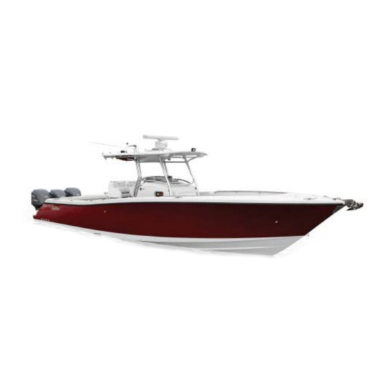
- Page 2 388CC SPECIFICATIONS LENGTH: 37’10” (11.5m) BEAM: 11’ (3.4m) DRAFT (boat only): 22” (56cm) BOAT WEIGHT: 9600lbs (4354kg) WEIGHT CAPACITY: 4300lbs (1950kg) PERSON CAPACITY: PERSON WEIGHT: 1980lbs (900kg) FUEL CAPACITY: 450gal (1703.44L) TRANSOM HEIGHT: Twin-30” OR Trip 25”-30”-25” MAX POWER: 1050hp...
- Page 3 Dear EdgeWater 388CC Owner: Congratulations on purchasing one of the finest offshore boats ever built. It has been constructed with care from the finest available materials. At EdgeWater we take great pride in the quality and craftsmanship that goes into each boat. We believe you’ll have many years of enjoyment from your new EdgeWater and thank you for entrusting your leisure time to one of our fine products.
- Page 4 Service Information Please fill out the information below completely. It will help us in assisting you in the event your EdgeWater 388CC needs service. Customer Name Address City State Phone Cell Business E-mail Address Dealer Name Address City State Phone...
-
Page 5: Table Of Contents
Table of Contents Chapter 1 General Information ..............6 1.1 General ..........................6 1.2 Owner / Operator Responsibilities ..................6 Chapter 2 Helm Control Systems..............7 2.1 General ..........................7 2.2 Steering System........................7 2.3 Engine Throttle and Shift Controls ..................7 Chapter 3 Propulsion System..............8 3.1 General .......................... - Page 6 Chapter 8 Safety Equipment..............18 8.1 Required Safety Equipment ....................18 8.2 Suggested Safety Equipment - Inshore ................19 8.3 Suggested Safety Equipment – Offshore................19 Chapter 9 Safe Operation.................20 9.1 Pre-Cruise Check List ......................20 9.2 Basic Rules of the Road ....................21 9.3 Safe Operation........................
-
Page 7: Chapter 1 General Information
1/General Information 1.1 General Your EdgeWater 388CC is a semi-custom offshore fishing vessel that is designed to be powered by dual or triple outboard engines. 1.2 Owner / Operator Responsibilities Registration Registering your boat is important to you. Federal Law requires that all powered, undocumented vessels be registered in their state of principal use. -
Page 8: Chapter 2 Helm Control Systems
2/Helm Control Systems 2.1 General The helm station is the control center for the boat. The main control systems are the engine throttle and shift controls, the steering system, the trim tab controls, and the bow thruster control. These provide the operator the ability to control speed, direction, boat trim, and attitude. Each manufacturer provides manuals on the operation and use of their systems. -
Page 9: Chapter 3 Propulsion System
3/Propulsion System 3.1 General Your new EdgeWater 388CC is designed to be powered by dual or triple outboard motors. Most 2-cycle outboards currently use an automatic system to mix the oil with the engine before the engine uses it. If equipped with 2-cycle engines, there will be oil tanks located inside the mechanical access space and the oil fills will be located on the motorwell side of the aft deck. -
Page 10: Engine Cooling System
Do not paint your outboard’s lower units with paints designed for boat hulls. Some can cause severe damage to your engine. Check with your engine manufacturer to get their recommendation. Do not attempt control adjustments unless you are very familiar with their function, operation and adjustment. -
Page 11: Engine Power Tilt And Trim
The power tilt and trim system on your outboard(s) provides the ability to optimize the running angle of your EdgeWater 388CC to allow for load and sea conditions. Moving the outboard lower unit toward the transom is generally referred to as trimming “in”, while moving the outboard lower unit away from the transom is referred to trimming “out”. - Page 12 Temperature Gauge This is designed to monitor the operating temperature of your engine’s cooling system. A sudden rise from the normal should be investigated to determine if there is an obstruction in the cooling system. Water Pressure Gauge This gauge measures pressure in the engine cooling system. If the pressure changes from the norm it could indicate a complete or partial blockage in the system or a water pump problem.
-
Page 13: Chapter 4 Fuel System
4/Fuel System 4.1 General Your EdgeWater 388CC is equipped with a 450-gallon “main” fuel tank. The inspection ports for the fuel tanks are located in the floor at the helm station for the main tank and between the aft fishbox lids for the auxiliary tank. If equipped with the auxiliary tank, electronic switching valves are located in the aft bilge compartment and are controlled by a dash-mounted switch. -
Page 14: Fueling
5/Electrical Systems 5.1 General Your EdgeWater 388CC operates on a 12volt DC system, similar to your automobile. The batteries, (2 standard plus 1 per engine), are typically lead acid type and require similar maintenance to your automobile’s battery. A standard battery isolator and all batteries are located... -
Page 15: Panel Switches
Your EdgeWater 388CC is equipped with panel mounted breakers. Two panels are at the helm area and one is inside the console. On the 388CC helms’ main switch panel, switches are provided for navigation lights, decklights, forward, aft, and sump bilge pumps, two for livewells, raw and freshwater pumps, fwd and aft fishwell pumpouts, fwd and aft spreader lights for t- or hard tops, helm, deck, &... -
Page 16: Chapter 6 Raw, Waste & Freshwater Systems
6/Raw, Waste & Freshwater Systems 6.1 General Your boat is equipped with fresh, waste, and raw water systems. The freshwater components include a freshwater tank, distribution lines, two sink/shower faucets, and a pump. The standard raw water system consists of a two high-speed pick-ups located on the transom, three pumps, two washdown outlets, distribution lines, and one or more livewells. -
Page 17: Waste System
When activated, the pump’s pressure switch will automatically control the pump. It is normal for the pump to cycle on and off in response to flow rates and water demand. Always turn off the freshwater pump switch when leaving the boat unattended. Operating instructions for the freshwater system Fill holding tank with drinkable water, using water fill located on the starboard side gunwale. -
Page 18: Chapter 7 Drainage System
Violators are subject to a penalty of $10,000. 7.4 Locker & Fishbox Drains On the 388CC there is a forward anchor locker that drains directly through the hull. The forward and aft fishboxes are drained to diaphragm pumps that are controlled by the fishbox pumpout switches on the helm switch panel. -
Page 19: Chapter 8 Safety Equipment
You must have an efficient means of making a proper sound signal in the event of distress or poor visibility. Your 388CC is equipped with a horn as standard equipment, but a good back up such as a bell, whistle, or hand-held horn should also be carried. -
Page 20: Suggested Safety Equipment - Inshore
Never discharge your fire extinguisher to see if it still works. This will cause it to lose pressure. If it is accidentally discharged or if it is used on a fire, replace it immediately. 8.2 Suggested Safety Equipment - Inshore Suggested safety equipment, over and above the required equipment is: ... -
Page 21: Chapter 9 Safe Operation
It is advisable to carry jackets or foul weather gear in the event of adverse weather conditions. Your EdgeWater 388CC is equipped with a maximum capacity rating plate permanently affixed to the helm area of your boat. It will provide information regarding the maximum number of people you can safely have aboard, the maximum amount of weight the boat can safely carry, and the maximum horsepower your boat was designed to handle. - Page 22 Make sure someone else on-board knows how to operate the boat in the event you are injured and unable to operate the boat. If you are operating the boat for the first time, make sure you follow the engine manufacturer’s break-in recommendations. This will assure proper break-in and reduce the possibility of engine problems.
-
Page 23: Safe Operation
9.3 Safe Operation Getting Underway After clearing the dock, make sure the power trim (if so equipped) is trimmed down. (This will bring the boat up on plane more quickly and easily.) Give the engine sufficient throttle to bring it to plane briskly, then back down to the cruising speed of your choice, based on the sea conditions and your planned activity. -
Page 24: Stopping The Boat
Turn off all electronics and leave the battery switches in the off position. Remember, the bilge pump will operate properly even with the battery switches turned off. On a comforting note, your EdgeWater 388CC is fully self-bailing and unsinkable. Proper precautions, however, are always prudent. -
Page 25: Launching Your Boat
The trailer should be adequately sized for your boat. Allow about 10% above the maximum boat weight for trailer capacity. vehicle Make sure your vehicle is properly equipped to handle the load. This includes engine, hitch, frame, brakes, transmission cooler, and vehicle Trailer capacity. -
Page 26: Chapter 10 Routine Maintenance
Back the trailer into the water until the bunks are completely submerged, or until the middle roller is just touching the water. (This depth should provide enough to float the boat until the last minute and yet provide enough resistance from the trailer to stop the boat short of the winch stand.) Drive the boat onto the middle of the trailer. -
Page 27: Engine
Chrome Hardware Use a good metal polish and protect with wax. This should be done every couple of months or as soon as you notice any finish deterioration. Dupont® No.7 Chrome Polish works well. Plexiglas® Do not use products with ammonia on your Plexiglas® windscreen. It can mar the surface and reduce its transparency. -
Page 28: Chapter 11 Exterior Equipment
Remember, your anchor line should be a minimum of 7 times the depth in which you routinely operate. Your EdgeWater 388CC should have a minimum of 150 to 200 feet of ½” three strand nylon line. If you routinely venture offshore, remember the 7 times depth rule. This may sound like a lot but if your engine fails in 100 feet of water, maintaining your position will be very important to being recovered. -
Page 29: Chapter 12 Seasonal Maintenance
12/Seasonal Maintenance 12.1 Engine Refer to your engine manual for any specific information pertaining to your engine. For the fuel system, add a fuel stabilizer to a full fuel tank as per the stabilizer’s instructions. Run the engine for a minimum of 10 minutes to allow the fuel stabilizer to reach the engine. ... -
Page 30: Appendix
Appendix 388CC... - Page 32 Hydraulic Steering System...
- Page 36 Installation, Compensation, and Maintenance Instructions For all ® RITCHIE NAVIGATOR™ Compass Models Made in U.S.A. CAUTION: All Magnetic Compasses are vulnerable to magnetic interference, which will produce errors, called deviation. It is the Owner/Operator and/or Helmsman’s responsibility to make sure the compass is properly installed and compensated.
- Page 37 Most models have built-in lights which will require routing the wire or wires to your power source. To assure a clean installation you may want to wait and drill the routing holes after you are satisfied with the compass alignment. Specific model installation instructions are as follows: Note for all flush and bulkhead mount compasses: It is important that you use the mounting gasket included with each model.
- Page 38 (slot is facing aft). Step Four. Check compass alignment by running the boat in a Southerly direction, again keeping the mark lined up. If the compass is not correct at this time, there is an alignment error. To correct, rotate the compass itself to remove one half of this error.
- Page 40 We make the best boats better! ™ The world leader in trim tab, trolling motor and hatch lift innovation. oWNer’s maNUaL Featuring NEW waterproof Deutsch connectors!
- Page 41 Lenco Electric Actuators Lenco power explained… The entire Lenco Actuator is fully submersible, maintenance-free and sealed for life 6 foot leads with Deutsch connectors Corrosion proof, water tight Vandar top cap and mounts stand up to severe loads Buna-N SBR O-ring ensures absolute water-tight seal Tough, high-torque motor easily transfers 750 lbs (340.18 kg)
- Page 42 CONGRATULATIONS! You have just purchased the finest, performance trim tab system in the world! Welcome to the future. Lenco Trim Tabs make the single most important difference in the way your boat rides and performs. Lenco Trim Tabs make your boat ride smoother, drier, faster, and safer with increased fuel efficiency whether on a small skiff or a mega-yacht.
- Page 43 Contents Trim Tabs operation ....... . . 5 special Conditions ......6 safety .
-
Page 44: Trim Tabs
Trim Tab Operation Trim Tab Operation The Lenco Tactile Switch Lenco Trim Tab kits include two stainless steel is based on the position planes, two electromechanical actuators and of the bow. all mounting hardware for installation. (See available switch options on page 16.) The trim Lowers Lowers tabs operate independently of one another to... -
Page 45: Special Conditions
Trim Tab Operation SPECIAL CONDITIONS HEAD SEA Head Sea — Lower both tabs slightly by pressing BOW DOWn on both sides. This brings bow down while maintaining speed. This adjustment allows the hull of the boat to absorb the impact of the waves, resulting in a more efficient and smoother ride. -
Page 46: Additional Information
Trim Tab System Parts & Troubleshooting Stainless steel blade with hinge #20141-001 (B-9x12 dimensions of tab Electromechanical Actuator #101, #101 XD, #101 XDS, #102 XD Upper mounting bracket #15085-001 (116) Space saver upper mounting bracket #50225-001 (117) (optional) Lower mounting bracket #50014-001 (119) RetroFit Kit bracket #15085-001 (116) -
Page 47: Warranty
Trim Tab Installation Instructions Trim Tab Installation Instructions Warning: The following instructions contain important safety information and should be followed carefully. Failure to do so may result in injury and will void warranty. please read through the instructions in their entirety prior to beginning installation! TOOLS AND MATERIALS LIST •... - Page 48 Trim Tab Installation Instructions Trim Tab Installation Instructions 5/8" (1.59 cm) (for a 9" trim tab) and Standard Mount 3/4" (1.9) (for a 12" trim tab) above Fig. 2 the straight edge when held to the hull (see Fig. 2). When the trim tab is at the appropriate level, transfer 14"...
- Page 49 Trim Tab Installation Instructions Installation Instructions continued from page 9. Insert the actuator cable through the the helm is clear of wires and other transom. With the actuator loosely equipment that could be damaged. supported, start the provided #14 x Using the template on page 35, drill 1-1/4"...
- Page 50 Trim Tab Warranty Lenco Trim Tabs, Switches and replacement, you will be required to secure the replacement part Bennett RetroFit Kits carry a with a credit card prior to shipment 3-year limited warranty from (Visa, MasterCard, American the date of original purchase. Express, Discover).
- Page 51 Switch Wiring #15069-001 (124SSR) # 15069-001 (124SSR) Switch Template Page 27 note: In all cases, make sure control box is mounted with wires facing down toward deck. Lenco Marine...
- Page 52 Switch Wiring #15070-001 (123SC) # 15070-001 (123SC) note: In all cases, make sure control box is mounted with wires facing down toward deck. Owner’ s Manual...
- Page 53 Dual Station Switch Wiring Switch Template Page 27 note: In all cases, make sure control box is mounted with wires facing Lenco Marine down toward deck.
- Page 54 Dual Actuator Switch Wiring # 15071-001 (123DRSC) note: In all cases, make sure control box is mounted with wires facing Owner’ s Manual down toward deck.
- Page 55 Optional Switches Complete your trim tab system with the latest switch technology — totally waterproof, maintenance-free, easy-to-install tactile switches. Lenco Switch Options #1 5069-001 (124SSR) – Standard Tactile Switch w/Retractor for all single actuator 12-volt trim tab systems #1 5070-001 (123SC)- L.E.D. Indicator Tactile Switch w/Retractor and Self-Check for all single actuator 12- or 24-volt trim tab systems #1 5071-001 (123 DRSC) - Dual Actuators L.E.D.
-
Page 56: Operation
Switch Operation SWITCH OPERATION bottom to top to indicate self test at power up. If there is a problem with The operation of the indicator switch an actuator connection the L.E.D. is based on the position of the bow. displays shows every other light To lower the starboard bow, press red ”On“... - Page 57 RetroFit Kit for Bennett Trim Tabs Installation Instructions Electric RetroFit Kit for Bennett Trim Tabs Installation Instructions Lenco Marine’s RetroFit Kit is designed as a direct replacement for the Bennett 4-ring standard trim tab actuator. Note: Bennett Joystick Control can not be retrofitted to the Lenco Actuators.
-
Page 58: Wiring Instructions
RetroFit Kit for Bennett Trim Tabs Installation Instructions Lenco wire feeds through existing oil line hole in transom Lenco upper mounting bracket fits existing Bennett mounting Existing Bennett holes lower actuator bracket Existing Bennett trim tab plane and hinge 7) now you will need to hook up the recommend using 3M 5200 adhesive caulking to bed the upper bracket Lenco Actuator wires inside the... - Page 59 RetroFit Kit for Bennett Trim Tabs Wiring Instructions Wiring Instructions for Electric RetroFit Kit for Bennett Trim Tabs 1) Remove all wires and all jumpers BOW DOWn should extend the (brass strips) on Bennett factory tabs while BOW Up should retract them.
-
Page 60: Upgrading And Retrofitting
Upgrading and Retrofitting Upgrading and Retrofitting Standard Tab to Troll’n Tab A 9x12 trim tab can be upgraded to 9x12 Troll’n Tab. Standard Tab Blade Upgrade For a larger trim tab blade a 9x12 blade can be retrofitted with a 12x12 blade. Edge Mount Kit Upgrade Since the placement of the upper bracket is lower then a standard mount, an edge mount can be retrofitted only with another edge mount trim tab. -
Page 61: Actuators
Actuators " " The 101 XD Actuator (6.35 cm) (6.35 cm) The 101 Actuator is used mostly is used in all TT & with HD, XD, High Standard kits. Performance & Super Strong tabs. 101 Actuator 101 XD Actuator " stroke Overall length tip to "... - Page 62 Hatch Lift Warranty Lenco Hatch Lifts carry a an immediate replacement, you 2-year limited warranty from will be required to secure the replacement part with a credit the date of original purchase. card prior to shipment (Visa, When possible, please refer to MasterCard, American Express, our troubleshooting guide on our Discover).
-
Page 63: Hatch Lifts
Hatch Lifts — Installation/Operation Lenco Hatch Lift Installation/Operation Due to the many different variables involved S = Short. All part numbers ending in S have the same stroke but in a 4" (10.16 cm) with the numerous applications for Lenco shorter length. -
Page 64: System Parts
Hatch Lifts — Mounting/Parts Lenco Hatch Lift Mounting LBS/KG Length IN/CM Length IN/CM Hatchlift YxW÷X=Force 1. Follow the chart above to figure out not bind when fully closed. The hatch load on the hatch lift. Maximum load lift does not stop pulling until it has is 500 lbs. - Page 65 Product Summary Standard Trim Tab Kits • Standard trim tab kits include: two #101 actuators with extension harnesses and Deutsch connectors, two stainless steel blades, and all mounting hardware. See switch selections on page 16 for available options • Available in standard mount and edge mount (space saver mount) •...
-
Page 66: Switch Template
Product Summary/Switch Template High Performance Tabs - Single & Dual Actuator • High performance tab kit includes: two 12-volt Extreme Duty Actuators with 316 SS billet ram with 3/8" (.95 cm) SS bolts, two 7-gauge flat-304 electro-polished stainless blades. • Full transom back plate with adjustable C-channel, 3/8" (.95 cm) bolts and super duty hinge with 3/8"... - Page 67 DoN’t WorrY… we’ve got your back. Lenco Marine Inc., 4700 Municipal Court • Stuart, Florida 34997 772-288-2662 • 772-288-2566 fax • www.lencomarine.com 8-07...
- Page 68 31295 / 31395 - SERIES AUTOMATIC WATER SYSTEM PUMP FEATURES • Smooth Flow • Self-Priming up to 10 feet (3m) • Dry running capability • Soft noise absorbing mounts • Snap-fit port fittings • Built-in bypass — less pulsation • Reduces need for accumulator tank •...
- Page 69 FIG. 2 FIG. 1 INSTALLATION STEP 3 STEP I Slide rubber mounts fully into 4 mounting tracks. Remove shipping plugs from pump ports. There may be slight STEP 4 amount of water that drains out of the pump as all pumps are Mount pump horizontally in an accessible location or vertically with tested at the factory before shipment.
- Page 70 FIG. 4 EXPLODED VIEW AUTOMATIC WATER SYSTEM PUMP SERVICE PARTS SERIES SERIES KEY# DESCRIPTION 31395 - XXXX 31295 - XXXX Pressure Switch (25 psi) 18916-1025 18916-1025 (40 psi) 18916-1040 (50 psi) 18916-1050 Pumphead Assembly (25 psi) 18914-1025 18914-0025 (40 psi) 18914-1040 (50 psi) 18914-1050...
- Page 71 Sanitizing Potable water systems require periodic maintenance to deliver a consistent flow of fresh water. Depending on use and the environment the system is subjected to, sanitizing is recommended prior to storing and before using the water system after a period of storage.
- Page 72 — 31595-SERIES — 31600-SERIES WATER SYSTEM PUMPS — 31620-SERIES — 31630-SERIES PAR-MAX 2+ – 2.8 GPM (10.6 LPM) PAR-MAX 3 – 3.5 GPM (13.2 LPM) PAR-MAX 4 – 4.3 GPM (16.3 LPM) FEATURES • Self-Priming to 10 ft. (3 m) •...
- Page 73 INSTALLATION QUICK EASY INSTALLATION VERSATILE SNAP-IN PORTS Shower Sink Hot Water Water Line Heater Check Cold Water Sink Valve Line Tank Fill Vent Accumulator Tank Pumpgard™ Strainer Water Supply Tank City Water Intake Pressure Regulator Water Pressure Pump MOUNTING switch is positive. Black wire from the motor is negative. The PAR-MAX pumps are self-priming and may be locat- Select wire size from chart below.
- Page 74 WARNING: DISCONNECT POWER TO PUMP AND OPEN VALVE TO RELIEVE WATER PRESSURE PRIOR TO SERVICING PUMP EXPLODED VIEW * Service kit includes Keys 2, 3 and 4B, C, D and 8 DESCRIPTION 31595-SERIES 31600-SERIES 31620-SERIES 31630-SERIES Upper Housing XXXXX-0092 18910-4040 18910-4040 18910-4040 18910-4040...
- Page 75 TROUBLESHOOTING PUMP FAILS TO TURN OFF AFTER ALL FIXTURES PULSATING FLOW – PUMP CYCLES ON AND OFF ½ Restricted pump delivery. Check discharge lines, fit- ARE CLOSED ½ Empty water tank. tings and valves for undersizing or clogging. Clean ½ Punctured pump diaphragm (water leak). screens in faucets.
- Page 76 Instruction Manual Ultima Bilge 600GPH, 800GPH, 1000GPH, 1250GPH Read and understand this manual prior to operating or servicing this product. IB-123/01 (0912)
- Page 77 INDEX Svenska ..........................3 English ........................... 6 Deutsch ..........................9 Français ..........................13 Español ..........................16 Italiano ..........................19 Part No. list ........................22 Electromagnetic Compatibility Directive 89/336/EEC EN55014-1: 1993/A:1997 /Radio disturbance Recreational Craft Directive 94/25/EEC ISO 8846: 1990/Electrical devices - Protection against ignition of surrounding flammable gases ISO 8849: 1990/Electrically operated bilge pumps ISO 10133: 1994/Electrical systems - Extra low-voltage DC installations Warranty Information...
- Page 78 > Svenska Ultima Bilge länspump Varning: Vänligen läs igenom och följ samt- brandfara. liga anvisningar innan installation och an- vändning av denna produkt. Installation av Ultima Bilge: Koppla alltid bort spänningskällan vid in- Varning: Vid installation av Ultima Bilge, stallation, service eller underhåll av denna säkerställ att pumpen är fri från alla hinder, produkt.
- Page 79 > Svenska monteras, säkerställ att backventilen mon- Placera fingrarna teras i Duraport innan slangen och anslut- på kretsarna ningsöppningarna installeras. Backventilen för att testa pumpen för [1 1/8” eller 1 ¼”] modellen innefattar en rostfri bricka och en klaff. För att in- Nivå, stallera backventilen, placera den rostfria parallellt...
- Page 80 > Svenska Svart till minus (-) Brun till plus (+) (Manuell överkoppling) Vrid av (moturs) Brun/vit till plus (+) PUMP pumphjuls- (Automatisk funktion) skydd Tryck ned de 2 stiften ***Säkerställ att du har minst 25mm fritt ut- rymme från avkännarna på Ultima Bilge till Garantiinformation väggar eller omgivning.
- Page 81 > Svenska Kopplingsschema Svart PUMP Brun 12V DC Batteri Test Cirklar Manuell Brun/vit Automatisk Säkring Kontrollpanel, 3-vägsbrytare Om du använder en 3-vägsbrytare, kan du koppla din pump så att den fungerar i den manuella vidarekopplings- eller automatiska driften. Som visas på diagrammet, anslut den svarta (-) jordade ledningen till den negativa bat- teriterminalen.
- Page 82 > English Ultima Bilge - Automatic Bilge Pump Caution: Please read and follow all instruc- Installing the Ultima Bilge Pump: tions before installing and using this prod- Caution: When installing the Ultima Bilge uct. Always disconnect power sources dur- Pump, make sure that pump is clear of all obstacles, especially near the detector ing installation, servicing or maintenance of this product.
- Page 83 > English make sure to install the check valve before Place fingers on circles to test the installing the hose and ports. The check pump valve for the [1 1/8” or 1 ¼”] model will include a stainless steel washer and a flap- Level, per.
- Page 84 > English Black to negative(-) Brown to positive (+) (Manual override) Lock impeller guard by twisting counter Brown/white to positive (+) PUMP clockwise (Automatic operation) Depress (2) tabs ***Make sure to have at least 1 inch [25MM] of clearance from the sensors on the Ultima Warranty Information Bilge pump to any wall or souroundings.
- Page 85 > English Wiring Scheme Black PUMP Brown 12V DC Battery Test Circles Manual Brown/White Automatic Appropriate inline fuse Three way panel switch If you are using a 3-way switch, you can wire your pump to operate in the manual over- ride or automatic operation.
- Page 86 > Deutsch Ultima Bilge -Lenzpumpe Vorsicht: Bitte lesen und befolgen Sie vor der Installation der Ultima-Lenzpumpe: Installation und Einsetzung dieses Produktes alle Anweisungen. Vorsicht: Stellen Sie bei der Installation Trennen Sie das Produkt während der In- der Ultima-Lenzpumpe sicher, dass es keine stallation, Instandhaltung oder...
- Page 87 > Deutsch stallieren. Für 1 1/8”-Modelle befestigen Sie Setzen Sie ihre Finger auf die Kreise, Ihren Schlauch über dem Gewindeanschluss um die [1 1/8” oder 1 ¼”]. Verwenden Sie einen Pumpe Schlauch aus rostfreiem Stahl. Falls Sie ein zu prüfen. optionales Rückschlagventil installieren, stel- Eben, len Sie sicher, dass Sie das Ventil am Dura-...
- Page 88 > Deutsch Schwarz an negative(-) Verschließen Sie den Braun an positiv(+) Antriebs- (Manuelle Steuerung) radschutz, indem Sie ihn gegen Braun/Weiss den Uhrzeiger- PUMPE an positive (+) sinn drehen (Automatikbetrieb) Drücken Sie die (2) Verschlussnasen *** Stellen Sie sicher, dass Sie einen Abstand von mindestens 1 Zoll [25 mm] von den Sen- soren der Ultima Lenzpumpe zu jeglichen Wän- den oder der Umgebung haben.
- Page 89 > Deutsch Schaltplan Schwarz PUMPE Braun 12V Gleich- strombatterie Prüfkreise Manuell Braun/Weiss Automatisch Inline Sicherung Dreiwegeschalter Mit einem Dreiwegeschalter kann die Pumpe sowohl manuell als auch automatisch be- tätigt werden. Wie aus der Abbildung hervorgeht, wird der schwarze (-) Masseleiter an den Minuspol der Batterie angeschlossen.
- Page 90 > Français Ultima Bilge - Pompe de Fond de cale Ultima Bilge Attention: Veuillez SVP lire et suivre toutes Installation de la pompe de fond de cale les instructions avant l’installation et l’usage Ultima Bilge: de ce produit. Toujours déconnecter l’alimen- tation électrique durant les travaux d’instal- Attention: Lors de l’installation de la pompe de lation, d’entretien ou de maintenance de ce...
- Page 91 > Français 1/8” ou 1 ¼”]. Utilisez des brides pour tuyaux Mettez les doigts sur les cercles pour en acier inoxydable pour maintenir le tuyau essayer sur les raccords. Si vous installez un clapet la pompe de anti-retour optionnel, assurez-vous d’ins- taller le clapet de anti-retour avant d’installer Niveau, le tuyau et les raccords.
- Page 92 > Français Noir au negatif(-) Verrouillez le capot de Brun au positif(+) la turbine (Fonctionnement en le pivotant manuel prioritaire) dans le sens POMPE contraire des Brune/Blanc au aiguilles positif (+) d’une montre (Fonctionnement automatique) Appuyer sur les (2) tirettes ***Assurez-vous d’avoir au moins 1 pouce [1 inch = 25MM] de distance entre les capteurs de la pompe de fond de cale Ultima Bilge et...
- Page 93 > Français Tableau de câblage Noir POMPE Brun − 12V DC Batterie Circuit de test Manuel Brun/blanc Arret Auto- Fusible matique Panneau d’interrupteur a trois voies Si vous utilisez une interrupteur à trois voies, vous pouvez câbler votre pompe de manière à...
- Page 94 > Español Ultima Bilge - Bomba de Desfonde Ultima Cuidado: Por favor, lea y siga todas las Asegúrese de usar el tamaño de fusible instrucciones antes de instalar y usar este apropiado recomendado por el modelo de producto. su bomba. Usar el fusible equivocado pue- Desconecte siempre las fuentes de ener- de provocar daños personales, daños a la gía durante la instalación, el servicio o...
- Page 95 > Español Para los modelos de descarga de ¾” pon- está hecho de Nitrilo que solo se usa para ga su tubería flexible sobre el Duraport. aplicaciones de agua. La válvula de control Use abrazaderas de acero inoxidable para también reducirá el flujo de la bomba. El flu- asegurar la tubería flexible.
- Page 96 > Español namiento de la bomba ponga dos dedos acumulado en el filtro también. Después sobre las áreas circulares levantadas en de que el propulsor esté limpio, vuelva a la parte trasera de la bomba. Después de poner la seguridad del propulsor alineando un corto espacio (5 segundos), la bomba las lengüetas con las ranuras y girando al debería encenderse.
- Page 97 > Español Tabla de cableado Negro BOMBA Marrón − 12V DC Battería Círculos de prueba Manual Marrón/ Blanco Automático Fusible Interruptor del panel de trés vías Si está usando un interruptor de 3-vías, puede cablear su bomba para funcionar de forma manual o automática.
- Page 98 > Italiano Ultima Bilge - Pompa di sentina Ultima Attenzione: prima dell’installazione e dell’uso Installazione della pompa di sentina Ultima: di questo prodotto vi preghiamo di leggere e seguire attentamente tutte le istruzioni. Attenzione: Durante l’installazione della pom- Interrompete sempre la corrente elettrica pa di sentina Ultima, assicuratevi che la pompa durante l’installazione o la manutenzione di sia libera da ogni tipo di ostacolo, in particola-...
- Page 99 > Italiano il flessibile ai fori. Se desiderate montare la Mettete le dita sui cerchi valvola di sicurezza opzionale, assicuratevi per testare di installarla prima di fissare il flessibile ai la pompa fori. La valvola di controllo per il modello [1 1/8”...
- Page 100 > Italiano Nero per il negativo(-) Chiudere la custodia del Marrone per il positivo girante (passaggio all’inter- ruotando vento manuale) in senso POMPA antiorario Marrone/bianca per il positivo (funzionamento automatico) Premere (2) linguette ***Assicuratevi che ci sia almeno 1 pollice [25 mm] di spazio libero tra i sensori della pompa di sentina Ultima e qualsiasi pare- Garanzia...
- Page 101 > Italiano Schema elettrico Nero POMPA Marrone − 12V DC Batteria Circolo di testo Manuale Marrone/ Spento Bianco Automatico Fusible Pannello interrut- tore a tre uscite Se si usa un interruttore a 3 uscite, collegare la pompa per funzionare in modo manuale o automatico.
- Page 102 Technical Specifications: Part No. Dimensions: L=5.60” [142 MM] Part Number Description W=3.25” [82 MM] 32-47258 Ultima Bilge 600 H=4.15”[105 MM] Weight: 1.45 LBS [0.66 KG] 32-47259 Ultima Bilge 800 Material of 32-47260 Ultima Bilge 1000 construction: Seal: Lip Seal 32-47261 Ultima Bilge 1250 Fuse Size: 5A @ 12 VDC...
- Page 103 Besök www.johnson-pump.com för mer information om vår världsomspännande organisation, våra godkännanden, certifieringar och lokala representanter. SPX Corporation förbehåller sig rätten att ändra design och material utan föregående avisering. Designelement, konstruktionsmaterial och dimensioner som beskrivs i denna bulletin gäller endast som information och skall alltid bekräftas skriftligt för att vara gällande. Für weitere Informationen über unsere weltweiten Standorte, Zulassungen, Zertifizierungen und unsere Vertreter vor Ort, besuchen Sie bitte unsere Webseite: www.johnson-pump.com.
- Page 104 Instruction Manual Submersible Bilge Pump L1600, L2200, L4000 Read and understand this manual prior to operating or servicing this product. IB-106/03 (0911)
- Page 106 Index - Indice Svenska .............................4 English ............................6 Deutsch .............................8 Français ..........................10 Español ........................... 12 Italiano ........................... 14 Fig............................16 Besök www.johnson-pump.com för mer information om vår världsomspännande organisation, våra godkännanden, certifieringar och lokala representanter. SPX Corporation förbehåller sig rätten att ändra design och material utan föregående avisering. Designelement, konstruktionsmaterial och dimensioner som beskrivs i denna bulletin gäller endast som information och skall alltid bekräftas skriftligt för att vara gällande.
- Page 107 > Svenska Dränkbar länspump L1600, L2200 och L4000, 12/24 V Dränkbar länspump för pumpning av länsvatten i marin miljö. Installeras i kölsvinet. Säkerhetsföreskrifter Typbeteckning Pumptyp Art nr • Pumpen får inte användas till annan vätska än vatten/länsvatten. L1600 12 V 32-1600-01 • Installera alltid pumpen enligt kopplings- L1600 24 V 32-1600-02 schemat, se sid 16-17.
- Page 108 > Svenska 4. Montera filtret. Använd rostfria skruvar vid montering på trä. Ska pumpen monteras på metall eller glasfiber, skruva först fast en träplatta att fästa filtret på. 5. Placera pumpen på filtret och se till att båda låstapparna ”snäpper” fast. 6.
- Page 109 > English Submersible bilge pump L1600, L2200 and L4000, 12/24 V Submersible bilge pump for pumping bilge water in marine environment. To be installed in the keelson. Security Type designation • The pump may not be used for other Pumptype Part nr liquids than water/bilge water. L1600 12 V 32-1600-01 • Always install the pump according to the L1600 24 V...
- Page 110 > English 3. Position the strainer so that the pump nozzle is in the proper position to connect to the discharge hose. 4. Mount the strainer. If attaching the strainer to wood, fasten with stainless steel screws. If attaching the strainer to metal or fiberglass, first mount a wooden block and then fasten the strainer to the wooden block.
- Page 111 > Deutsch Bilge-Tauchpumpe L1600, L2200 und L4000, 12/24 V Marine-Tauchpumpe zum Abpumpen von Bilgenwasser. Zur Installation im Kiel- oder Bilgenbereich. Sicherheitsvorschriften Modellvarianten • Die Pumpe darf nur zum Abpumpen von Pumpentyp Artikel Nr Bilge- und Seewasser verwendet werden. L1600 12 V 32-1600-01 • Die Pumpe muß...
- Page 112 > Deutsch 3. Den Saugkorb so plazieren, daß der Pumpenauslauf bei der Montage der Pumpe in die richtige Richtung zeigt. 4. Saugkorb montieren. Bei Montage auf Holz Schrauben aus Niro verwenden. Bei Anbringung auf Metall oder GFK zunächst eine Platte aus seewasserbeständigem Sperrholz montieren. Auf diese wird der Saugkorb befestigt.
- Page 113 > Français Pompe de cale submersible L1600 et L2200, 12/24 V Pompe de cale submersible pour eaux de cale en milieu marin. Pour installation en fond de cale. Spécifications du modèle Instructions de sécurité • La pompe ne peut être utilisée que pour Modèle Référence de l’eau ou pour les eaux de cale. L1600 12 V 32-1600-01 • Brancher toujours la pompe selon le...
- Page 114 > Français 3. Placer le filtre pour que la sortie de la pompe soit dirigée dans le bon sens lorsque la pompe est fixée sur le filtre. 4. Monter le filtre. Utiliser les vis inoxydables pour le montage sur du bois. Si la pompe doit être montée sur du métal ou des fibres de verre, commencer par visser une plaque en bois où...
- Page 115 > Español Bomba de achique sumergible L1600, L2200 y L4000, 12/24 V Bomba de achique sumergible para achicar agua en ambientes marinos. Para instalación en la contra- quilla. Instrucciones de seguridad Modelo • La bomba sólo debe utilizarse para agua. Tipo Ref. No • Instalar la bomba según el esquema eléc- L1600 12 V 32-1600-01 trico de las páginas 16-18.
- Page 116 > Español 3. Colocar el filtro de manera que la salida de la bomba quede orientada para conectar la manguera. 4. Montar el filtro. Utilizar tornillos de acero inoxidable si se hace el montaje sobre madera. Si la bomba se ha de montar sobre metal o fibra de vidrio, deberá colocarse una chapa de madera a la que se fijará...
- Page 117 > Italiano Pompa di sentina sommersa L1600, L2200 a L4000, 12/24 V Pompa di sentina sommersa per pompare l’acqua di sentina in ambiente marino. Per installazione in stiva. Istruzioni di sicurezza Specifica del tipo • La pompa no si può usare per altri liquidi Tipo Art No dell’acqua o dell’acqua di sentina. L1600 12 V 32-1600-01 • Installare sempre la pompa secondo il...
- Page 118 > Italiano 3. Sistemare il filtro in modo che la mandata della pompa, una volta che questa sia stata montata sul filtro, sia orientata nella direzione corretta. 4. Installare il filtro, usando le viti in acciaio inossidabile nel caso il fissaggio avvenga direttamente su legno.
- Page 119 UltimaSwitch Elektrisk installation utan strömbrytarpanel. Elektrisk installation med strömbrytarpanel.Electrical installation with panel. Electrical installation without panel. Elektrische Installation mit Schalttafel. Elektrische Installation ohne Schalttafel. Installation electrique avec panneau. Installation electrique sans panneau Instalación eléctrica con panel. Instalación eléctrica sin panel Installazione elettrica con pannello.
- Page 120 AS888 Elektrisk installation utan strömbrytarpanel. Elektrisk installation med strömbrytarpanel.Electrical installation with panel. Electrical installation without panel. Elektrische Installation mit Schalttafel. Elektrische Installation ohne Schalttafel. Installation electrique avec panneau. Installation electrique sans panneau Instalación eléctrica con panel. Instalación eléctrica sin panel Installazione elettrica con pannello.
- Page 121 Elektrisk installation utan strömbrytarpanel, med Elektrisk installation med strömbrytarpanel och elektronisk nivåströmbrytare elektronisk nivåströmbrytare Electrical installation without panel, with electronic Electrical installation with panel and electronic float float switch switch Elektrische Installation ohne Schalttafel, mit Elektrische Installation mit Schalttafel und elektronischem Schwimmerschalter elektronischem Schwimmerschalter Installation electrique sans panneau, avec...
- Page 123 SPX Johnson Pump Marine AB Nastagatan 19, P.O. Box 1436 SE-701 14 Örebro, Sweden Phone: +46 (0)19 21 83 00 Fax: +46 (0)19 27 23 72 E-mail: johnson-pump.marine@processequipment.spx.com For more information about our worldwide locations, approvals, certifications, and local representatives, please visit www.johnson-pump.com.
- Page 124 Type III MSD Waste Management System 38110 Système pour traitement des déchets MSD de type III Fäkalien-Entsorgungs- System Typ III MSD Sistema di gestione dei rifiuti MSD Tipo III Vuilwatersysteem type III MSD Typ III MSD- avfallshanteringssystem Sistema de gestión de residuos MSD Tipo III...
- Page 125 Type III MSD Waste Management System Rugged Polyethylene holding tank Barbed fittings for all hose connections Heavy Duty Macerator Evacuation pump Three run-dry and accidental activation safety features Touch-pad waste management control panel Additional dock side evacuation pick up puMp FEaTurES pump: Self-Priming Flexible Impeller with Stainless Steel Wearplate...
- Page 126 • 1x1” Overboard discharge port macerator pump out. Discharge: connect to the overboard discharge thru-hull fitting. *See plumbing diagram for recommended installation. Electrical: Wire the unit in an Independent Circuit. Consult the wiring table for fuse and wire size. Consult the wiring diagram for connections. Wiring Table AMP FUSE WIRE SIZE PER FEET OF RUN* VOLTAGE DRAW SIZE 0”-10” 10”-15” 15”-25” 25”-40” 40”-60” 12 Vdc 20 #16(1.5) #14(2.5) #14(2.5) #12(4) #6(16) 24Vdc #18(1) #16(1.5) #16(1.5) #14(2.5) #10(6) * Length of run is total length of the circuit from the power source to product and back to ground. Wire sizes listed are AWG gauge and metric millimeters.
- Page 127 Système pour traitement des déchets MSD de type III Réservoir en polyéthylène renforcé Embouts cannelés pour tous les raccords de tuyauterie Pompe de macération robuste Pompe d’évacuation Trois fonctions de sécurité contre le fonctionnement à sec et l’activation accidentelle Tableau de contrôle des déchets, à pavé tactile Poste de décharge à quai supplémentaire FONCTIONS DE POMPE Pompe : Turbine flexible auto-amorçante avec plaque d’usure en acier inoxydable Turbine : Composant Jabsco en nitrile Macérateur : Le broyeur en acier inoxydable réduit les déchets en particules de 3 mm maximum Joint d’étanchéité : Type capuchon Ports : Orifice d’entrée - Embout cannelé 38 mm et Orifice de sortie (mâle) norme N.P.T. 38 mm - Embout cannelé 19 mm Moteur : Type à aimant permanent, entièrement scellé, avec arbre en...
- Page 128 Orifice de décharge à la mer - Pompe de macération. Décharge - Raccord à l’embout du passe coque de dévidage à la mer. Consulter le diagramme de plomberie pour la méthode d’installation suggérée. Données électriques : Connecter l’unité à un circuit indépendant. Consulter le tableau de données électriques pour connaître la taille de fusible et de fil. Consulter le diagramme électrique pour les connexions. Tableau de données électriques AMP FUSIBLE TAILLE DE FIL POUR LONGUEUR DE CONDUCTEUR EN MÈTRES* TENSION TIRAGE TAILLE 0”-10” 10”-15” 15”-25” 25”-40” 40”-60” 12 Vdc #16(1,5) #14(2,5) #14(2,5) #12(4) #6(16) 24Vdc #18(1) #16(1,5)
- Page 129 Fäkalien-Entsorgungs- System Typ III MSD Robuster Sammeltank aus Polyethylen Schlauchstutzen für alle Schlauchanschlüsse Leistungsfähiger Zerhacker Absaugpumpe Dreifacher Trockenlauf- und Einschaltschutz Kontrolleinheit mit Folientastatur Zusatzanschluss für landseitige Entleerung PUMPENAUSFÜHRUNG Pumpe: trocken selbstansaugend mit flexiblem Impeller und Edelstahlverschleißplatte Impeller- werkstoff: Jabsco Nitril Edelstahlmesser zerkleinert Feststoffe auf < 3mm Zerhacker: Dichtung: Wellendichtring (Simmerring) Anschluß: Einlass 38mm Ø / 1 ½“ NPT, Auslass 25mm Ø Motor: Permanentmagnet, gekapselt, Edelstahlwelle, mit Trockenlaufschutzvorrichtung zum Abschalten der Pumpe bei Flüssigkeitsmangel, pulverbeschichtetes Gehäuse, Endkappen und Lager abgedichtet Systemmerkmale Füllstandsanzeige: Bei Betätigung leuchtet die Füllstandsanzeige 1 Minute lang auf. Wenn der Tank voll ist, meldet die Anzeige dem Benutzer durch automatisches Blinken, dass der Tank zu leeren ist. Standbymodus: Sollte die blinkende LED stören, lässt sich das System in den Standbymodus versetzen. Diesen verlässt es, wenn das System abgeschaltet oder der Füllstand im Tank erhöht wird. HINWEIS: Ab 7/8 vollem Tank ist kein Standbymodus möglich.
- Page 130 Elektroanschluss: Für das System einen separaten Stromkreis verwenden. Siehe Tabelle bezüglich Sicherung und Kabelquerschnitt. Siehe Schaltplan bezüglich der Anschlüsse. Kabeltabelle Kabel-Ø/m Kabel * Spannung Amp Sicherung 0”-10” 10”-15” 15”-25” 25”-40” 40”-60” 12 V #16(1,5) #14(2,5) #14(2,5) #12(4) #6(16) 24V #18(1) #16(1,5) #16(1,5) #14(2,5) #10(6) * Strecke ist die Gesamtlänge von der Stromquelle zum System und zurück zur Erdung. Die Kabelquerschnitte sind in AWG und Millimeter angegeben. Wartung: Das System sollte von Zeit zu Zeit mit klarem Wasser durchgespült werden um Schlamm und Schmutzrückstände zu entfernen. Dies sollte mindestens einmal jährlich erfolgen. Die Pflegeanweisungen für die Zerhackerpumpe sind dem Datenblatt der Baureihe 18590 unter Wartung zu entnehmen. Überwinterung: Das gesamte System ist zu entleeren, die Leitungen und die Pumpe zu reinigen. Pos. Bezeichnung Batterie Sicherung Fäkalien-Entsorgungssystem...
- Page 131 Sistema di gestione dei rifiuti MSD Tipo III Robusta tanica di raccolta in polietilene Attacchi dentati per tutti i collegamenti dei tubi Maceratore per servizio gravoso Pompa di evacuazione Tre funzioni di sicurezza per funzionamento a secco e contro l’attivazione accidentale Pannello di comando con sistema touchpad Ulteriore presa di evacuazione in banchina CARATTERISTICHE DELLA POMPA Pompa: girante flessibile autoadescante con piatto d’usura in acciaio inossidabile Girante: composto in nitrole Jabsco Maceratore: trituratore in acciaio inossidabile, riduce particelle massimo 3mm (1/8”) Tenuta: a becco Bocche: entrata - 38mm (1,5”) dentata per tubi e uscita (maschio) 1-1/2” N.P.T. – dentata per tubo 19mm (1”) Motore: a magnete permanente, completamente racchiuso, con albero in acciaio inossidabile, comprende dispositivo di protezione in caso di funzionamento a secco che spegne la pompa. Carcassa verniciata a polvere con flange e cuscinetti sigillati Caratteristiche del sistema Indicazione del livello: quando viene premuto, l’indicatore del livello si illumina per 1 minuto. Quando la cassa è piena, l’indicatore lampeggia automaticamente avvisando l’utente di vuotare la cassa.
- Page 132 Parte elettrica: Cablare l’unità in un circuito indipendente. Per le dimensioni dei fusibili e dei fili, vedere la tabella del cablaggio. Per le connessioni, vedere il diagramma del cablaggio. Tabella del cablaggio DIMENSIONE DIMENSIONE FILI IN METRI* VOLT. AMP. FUSIBILE 0”-10” 10”-15” 15”-25” 25”-40” 40”-60” 12 V CC #16(1,5) #14(2,5) #14(2,5) #12(4) #6(16) 24V CC #18(1) #16(1,5) #16(1,5) #14(2,5) #10(6) * La lunghezza del percorso è la lunghezza totale del circuito dalla fonte di energia al prodotto e di nuovo alla messa a terra. Dimensioni dei fili elencate sono in calibro AWG e in millimetri metrici. Manutenzione: Per mantenere l’unità in buone condizioni d’esercizio, lavare con acqua pulita per rimuovere ogni accumulo di sporco e detriti. Si consiglia di fare questo lavaggio almeno una volta all’anno. Per la manutenzione della pompa del maceratore, vedere il foglio informativo Maceratore Serie 18590, Sezione Manutenzione.
- Page 133 Vuilwatersysteem type III MSD Robuuste polyethyleen opvangbak Alle slangkoppelingen voorzien van draad fittingen Zware versnijderpomp Afvoerpomp Drie beveiligingen tegen drooglopen en ongewilde activering Touchpad bedieningspaneel Extra afvoerbuis aan walkant KENMERKEN VAN DE POMP Pomp: zelfaanzuigende buigzame impeller met roestvrijstalen slijtplaat Impeller: Jabsco nitril compound Versnijderpomp: roestvrijstalen hakker reduceert tot deeltjes van max. 3 mm (1/8”) Afsluiting: liptype Aansluitingen: inlaat: 38 mm (1-1/2”) draadfitting – uitlaat: 38 mm (1-1/2”) N.P.T. (mannetje) 19 mm (1”) draadfitting Motor: permanente magneetmotor, volledig ingesloten, roestvrijstalen as, voorzien van droogloop beveiliging die de pomp uitschakelt. Gepoedercoate behuizing met afgedichte eindafdekplaten en lagers. Kenmerken van het systeem: Vulindicator: na indrukken blijft de vulindicator gedurende 1 minuut branden. Als de tank vol raakt, begint de indicator automatisch te knipperen om de gebruiker te waarschuwen dat de tank moet worden leeggemaakt Slaapmodus: als het knipperende ledje stoort, kan de eenheid in slaapmodus...
- Page 134 Elektrisch: Sluit de eenheid aan op een onafhankelijk stroomcircuit. Raadpleeg de bedradingstabel voor informatie over de zekering en de kabels. Raadpleeg het bedradingsschema voor aansluitingen. Bedradingstabel MAX. KABEL PER VOET SERIELENGTE** SPANNING STROOM ZEKERING 0”-10” 10”-15” 15”-25” 25”-40” 40”-60” 1 2 V gelijkstroom 16 #16(1,5) #14(2,5) #14(2,5) #12(4) #6(16) 2 4 V gelijkstroom 8 #18(1) #16(1,5) #16(1,5) #14(2,5) #10(6) * De serielengte is de totale lengte van het circuit vanaf de stroombron tot aan het product en terug naar het aardpunt. De kabeldiktes zijn aangegeven in AWG-dikte en in millimeter. Onderhoud: Spoel het systeem met schoon water om het in goede werking te houden en eventuele vervuiling van bezinksel of afzetting te verwijderen. Aanbevolen wordt dit minstens een keer per jaar te doen. Voor onderhoud van versnijderpomp: zie onder Onderhoud op het gegevensblad van de 18590 serie versnijderpomp.
- Page 135 Typ III MSD- avfallshanteringssystem Stark septiktank av polyetylen Hullingförsedda kopplingar för alla slanganslutningar Kraftfull maceratorpump Evakueringspump Tre säkerhetsfunktioner för torrkörning och oavsiktlig aktivering Kontrollpanel för avfallshantering med tryckkänslig knappsats Ytterligare evakueringsutsug vid kajen PUMPFUNKTIONER Pump: Självsugande flexibel impeller med slitplåt av rostfritt stål Impeller: Jabsco-nitrilblandning Macerator: Kniv av rostfritt stål reducerar partikelstorleken till max. 3 mm (1/8 tum) Packning: Läpptätning Portar: Intag – 38 mm (1,5 tum) slanghulling och 38 mm (1,5 tum) N.P.T. (hane) Uttag – 19 mm (1 tum) slanghulling Motor: Permanentmagnet, helt innesluten, axel av rostfritt stål, inkluderar skyddsanordning mot torrkörning som slår av pumpen. Pulverbelagt hus med förseglade slutbälgar och lager Systemfunktioner Nivåindikator: När du trycker på nivåindikatorn tänds den 1 minut. När tanknivån är full blinkar indikatorn automatiskt för att varna användaren om att tanken bör tömmas. Viloläge: Om den blinkande lysdioden är störande kan enheten sättas i viloläge. Enheten lämnar viloläge om systemet slås av eller om nivån i tanken stiger. OBS! Enheten kan inte gå i viloläge om tanken är mer än 7/8 full.
- Page 136 Dra ledningar i enheten som en fristående strömkrets. Konsultera ledningstabellen för säkrings- och ledningsstorlek. Konsultera ledningsdiagrammet för anslutningar. . Ledningstabell AMPERE- SÄKRINGS- LEDNINGSSTORLEK PER LEDNINGSLÄNGD* SPÄNNING FÖRBRUKNING STORLEK 0”-10” 10”-15” 15”-25” 25”-40” 40”-60” 1 2 V likström #16(1,5) #14(2,5) #14(2,5) #12(4) #6(16) 2 4 V likström #18(1) #16(1,5) #16(1,5) #14(2,5) #10(6) * Med ledningslängd avses kretsens totala längd från kraftkällan till produkten och tillbaka till jord. Ledningsstorlekarna listas som AWG-mått och i millimeter. Underhåll: För att hålla systemet i gott skick ska det spolas rent med vatten för att avlägsna slam- och smutsavlagringar. Vi rekommenderar att denna process utförs minst en gång om året. För maceratorpumpunderhåll se underhållsavsnittet på databladet för maceratorn i serien 18590. Vinterförvaring: Töm allt vatten från systemet och se till att rör och pump inte innehåller avfallsprodukter.
- Page 137 Sistema de gestión de residuos MSD Tipo III Tanque de retención de polietileno resistente Conexiones acanaladas para todas las mangueras Macerador para servicio pesado Bomba de evacuación Tres funciones de seguridad contra funcionamiento en seco y activación accidental Panel de control táctil de gestión de residuos Recolector de evacuación adicional para muelle CARACTERÍSTICAS DE LA BOMBA Bomba: Impulsor flexible autocebante y placa de desgaste de acero inoxidable Rotor: Compuesto de nitrilo Jabsco Macerador: Cuchilla de acero inoxidable que reduce el tamaño de las partículas a un máximo de 3 mm Retén/Sello: Tipo de labio Lumbreras: Entrada – Acanalada para manguera de 38 mm y NPT de 1-1/2” (macho) salida – Acanalada para manguera de 19 mm Motor: Tipo de imán permanente, hermético, con eje de acero inoxidable. Incluye dispositivo contra funcionamiento en seco que apaga la bomba. Carcasa con recubrimiento pulvimetalúrgico, campanas de extremo y cojinetes sellados Características del sistema Indicación de nivel: El indicador de nivel se ilumina durante 1 minuto cuando se pulsa. Cuando el tanque está lleno, el indicador destella automáticamente a fin de alertar al usuario para que lo vacíe.
- Page 138 Sistemas eléctricos: Cablee la unidad en un circuito independiente. Consulte las especificaciones de tamaño de fusibles y cables en la tabla de cableado. Para conocer las conexiones, consulte el diagrama de cableado. Tabla de cableado TaMaÑo DEl TaMaÑo DEl cablE SEgÚn loS pIES DE rEcorrIDo* VolTaJE aMpEraJE FuSIblE 0”-10”...
- Page 139 DRILL PILOT 2 - 3/8 HOLES (4) (60.33 mm) (57.91 mm) 5/16 (7.94 mm) (19.05 mm) 3/4” DIA CLEARANCE HOLE FOR CONNECTOR 9/16 (14.29 mm) CONTROL PANEL MOUNTING TEMPLATE...
- Page 140 DIScoVEr JabSco’S coMplETE rangE oF WaSTE SySTEM proDucTS TWIST ‘n’ locK ™ Manual ToIlET DEluxE FluSh ElEcTrIc ToIlETS Designed to rival the comforts at home, the Jabsco Deluxe Flush combines sleek elegance along with the features required of a luxury marine toilet.
- Page 141 U.S.A +1 978 281 0440 UNITED KINGDOM +44 (0) 1992 450 145 JAPAN +81 (0) 45 475 8906 GERMANY +49 (0) 40 53 53 73 0 ITALY +39 039 6852323 Discover Jabsco at www.jabsco.com The products described herein are subject to the Jabsco one year limited warranty, which is available for your inspection upon request.
- Page 142 50890 Waste Pump Pompe d’eaux usées Fäkalienpumpe Pompa di scarico Afvoerpomp Tömningspump Bomba para desechos...
- Page 143 Waste Pump Robust Single Diaphragm Design Features Flexible installation No filter required Compact and simple design Self-priming to 3m (10ft) 12v and 24v variants Dry running capability Connections for 38mm (1 ") ports Up to 19 lpm (5 US gpm) flow Specifications Suction Lift: 3 meters (10ft) Relevant Standards:...
- Page 144 Maintenance WARNING: Always disconnect pump from power supply. Check all electrical connections periodically, particularly in salt water areas. Corrosion can cause loss of performance or non- operation in extreme cases. The motor should be protected with a corrosion inhibiting spray and any rust should be removed and the motor repainted.
- Page 145 Pompe d’eaux usées Modèle résistant à diaphragme unique Caractéristiques Flexibilité d’installation Ne nécessite pas l’emploi de filtre Modèle compact et simple Auto-amorçante jusqu’à 3 mètres Disponibles à 12 v et 24 v Capacité de fonctionnement à vide Raccords pour tuyaux de 38 mm Débit maximum de 19 l/minute Spécifications Hauteur d’aspiration : 3 mètres...
- Page 146 Maintenance AVERTISSEMENT : on doit toujours couper l’alimentation électrique de la pompe. Vérifier périodiquement tous les raccordements électriques, en particulier en milieux salins. Dans des cas extrêmes, la corrosion risque d’affecter le rendement ou la mise hors service. Il est nécessaire de protéger le moteur avec un inhibiteur de corrosion et d’enlever les moindres traces de rouille avant de repeindre le moteur.
- Page 147 Fäkalien- pumpe Robustes Design mit Einfachmembran Hauptmerkmale Flexible Installation Kein Filter erforderlich Kompakte und einfache Konstruktion Trocken Selbstansaugend bis zu 3m Erhältlich für 12 Volt und 24 Volt Trockenlaufsicher Anschlüsse 38mm Leistung bis zu 19 l/min Spezifikation Saughöhe: 3 Meter Normen: ISO 8846 MARINE und USCG Regulations for Ignition Protection...
- Page 148 Wartung ACHTUNG: Immer die Pumpe vom Stromnetz trennen! Alle elektrischen Anschlüsse in regelmäßigen Abständen überprüfen, dies gilt vor allem in Salzwasserbereichen. Korrosion kann zu Leistungsverlust oder in extremen Fällen zu einem Ausfall der Pumpe führen. Der Motor sollte mit einem korrosionshemmenden Spray geschützt werden;...
- Page 149 Afvoerpomp Robuust Eénmembraan Ontwerp Kenmerken Flexibele installatie Geen filter vereist Compacte en eenvoudige vormgeving Zelfaanzuigend tot 3m 12V en 24V modellen Droogloopvermogen Aansluitingen voor 38mm poorten Debiet maximaal 19 l/min Specificaties Aanzuighoogte: 3 meter Van toepassing zijnde normen: ISO 8846 MARINE en USCG voorschriften voor explosieveiligheid ISO 8849 MARINE Lenspompnorm Gebouwd conform ISO 15083 Specificatie...
- Page 150 Onderhoud WAARSCHUWING: Pomp altijd van de stroombron losmaken. Alle electrische aansluitingen periodiek controleren, speciaal in de nabijheid van zeewater. Corrosie kan lager rendement en in extreme gevallen, uitvallen van de pomp tot gevolg hebben. De motor is met een speciaal corrosiewerend middel behandeld. Mocht er onverhoopt toch roestvorming opkomen, deze verwijderen en de motor opnieuw verven.
- Page 151 Pompa di scarico Robusto design a singola membrana Caratteristiche Flessibilità di installazione Nessuna necessità di filtro Design semplice e compatto Autoadescante fino a 3m Modelli da 12 e da 24volt Capacità di funzionamento a secco Raccordi per sbocchi da 38mm Portata fino a 19 litri al minuto Specifiche tecniche Altezza di aspirazione: 3 metri...
- Page 152 Manutenzione AVVERTENZA: Staccare sempre la pompa dall’alimentazione elettrica. Controllare periodicamente tutti i collegamenti elettrici, soprattutto nelle zone affette da acqua di mare. La corrosione può infatti provocare perdite di rendimento o, in casi estremi, il mancato funzionamento. Il motore dovrà essere protetto con uno spray anticorrosione, avendo cura di eliminare tutte le eventuali tracce di ruggine e di riverniciare il motore.
- Page 153 Tömning- spump Robust membranpump för tömning av septiktank. Särdrag Flexibel installation Inget behov av filter Kompakt och enkel design 12V och 24V utförande Torrkörningssäker 38mm anslutningar Flöde 19 liter/min Specificationer Sughöjd 3 m Gällande normer ISO 8846 MARIN och USCG förordningar för antändningsskydd ISO 8849 MARIN länspumpstandard Byggd enligt ISO 15083 specifikation...
- Page 154 Underhåll VARNING! Koppla alltid loss ifrån ström- försörjningen innan demontering. Kontrollera alla elektriska anslutningar regelbundet, i synnerhet i saltvattenområden. Korrosion kan leda till försämrad funktion eller ingen funktion alls i extrema fall. Motorn bör skyddas med korrosionsskyddande spray, eventuell rost ska avlägsnas och motorn målas om.
- Page 155 Bomba para desechos De diafragma único de diseño sólido Características Instalación flexible No requiere filtro Diseño compacto y simple Autocebadora hasta 3m Variantes de 12v y 24v Capacidad para funcionar en seco Conexiones para puertos de 38mm Caudal de hasta 19 lpm Especificaciones Altura de aspiración: 3 metros Estándares pertinentes:...
- Page 156 Mantenimiento ADVERTENCIA: Siempre desconecte la bomba del suministro eléctrico. Controle todas las conexiones eléctricas periódicamente, en particular en las zonas de agua salada. La corrosión puede causar pérdida de prestaciones de la bomba y en casos extremos interrupción total del funcionamiento. Se deberá proteger el motor con un roc inhibidor de corrosión y se ío...
- Page 157 Rotation of Pump Head Rotation of Ports...
- Page 158 EXPLODED VIEW Part Numbers Model Voltage Fuse Sizes 50890-1000 50890-1100 Service Kit (Includes*) SK890 Service Kit - Waste Pump Description *Quantity in Kit Bracket Bush Clamp Bottom Clamp Top Con Rod Con Rod Plate Cover Diaphragm Hex Head Screw Hex Head Screw Motor Assembly Screw Recessed Pan Head Socket Head Screw...
- Page 159 DIMENSIONAL DRAWING mm (inches) Jabsco, 1 Kondelin Road, Cape Ann Industrial Park, Gloucester, MA 01930 Tel: +1 978 281 0440 Fax: +1 978 283 2619 Jabsco, Bingley Road, Hoddesdon, Hertfordshire EN11 0BU Tel: +44 (0) 1992 450 145 Fax: +44 (0) 1992 467 132 Fluid Products Canada, CANADA 55 Royal Road, Guelph, Ontario N1H 1T1...
- Page 160 ar.com...
- Page 161 Contents B10490 Issue 2. Pro-Series & Pro-Fish Windlass. Introduction 4. Maintenance Product support 4.1 General recommendations Approvals 5. Dismantling procedures Safety notices 5.1 Gypsy replacement (Pro-Series) General 5.2 Gypsy replacement (Pro-Fish) Electrical 5.3 Control arm replacement Electromagnetic compatibility 5.4 Gypsy drive shaft replacement & lubrication service Important information about this manual 5.5 Electric motor replacement...
- Page 162 Introduction 1. Installation Dear Customer, Important information about this manual 1.4 Accessories • Pro-Series & Pro-Fish Manual Thank you for choosing Lewmar windlass. Lewmar products are Throughout this manual, you will see safety and product damage Use only Lewmar parts and accessories to ensure top performance All references regarding installation and wiring world renowned for their quality, technical innovation and proven warnings.
- Page 163 2. Electrical wiring installation Fig. 1.6-2 Fig. 1.6-5 2.1 Electric cable selection 2.2 Wiring To achieve the best performance and to safeguard your electrical Plan the installation to suit the controls and give the operator a full 12” (300 mm) min. system it is essential that any electrical windlass be fi...
- Page 164 2.4 Model 700 - 12 V 2.5 Model 1000 - 12 V Choice of cable thickness depends on total cable length: Model Motor Breaker / Isolator Contactor Fig. 2.5-1 A + B + C + D + E = 12 V 50 A (68000348) Batter y to windlass, windlass to batter y.
- Page 165 3. Operating your windlass With whipping twine or similar, seize your rope 200 mm (8”) from the rope’s end and unlay the strands. Pass one strand through the chain link from one side and the other two strands from the opposite side. Remove seizing and complete As a prudent act of seamanship, anchor recovery operations Fig.
- Page 166 Seal (29) for signs of wear the Mainshaft must be removed as To reassemble, reverse the above procedure. Rebuild the 6.1-1 Parts list detailed below. If the seal is found to be unserviceable, the windlass applying generous amounts of grease. Gypsy Drive Shaft (30) will have to be withdrawn and the seal replaced.
- Page 167 7. Troubleshooting 8. Lewmar limited warranty 7.1 Anchor rode pays out independently clutch mechanism. Always secure the anchor rode independently LIMITED WARRANTY and Some states and countries do not allow the exclusion or limitation of incidental or consequential damages, so the above limitation or exclusion of the windlass whenever it is not being deployed or recovered.
- Page 168 © Copyright 2006 Lewmar Ltd. All rights reserved. B10490 Produced by T. Connell UK (+44) 023 9263 9265 Ref:T2116/04/2007...
- Page 169 50840 Series Low Pressure Centrifugal Pump “CYCLONE PUMP” Stainless Steel DC Motor / Pump Unit A range of Stainless Steel General Purpose Centrifugal pumps designed specifically for the marine and industrial markets. Typical applications would be for circulation applications such as hot water systems, livewell or bait tank installations Features &...
- Page 170 50840 Series Low Pressure Centrifugal Pump Operation Wiring Instructions Make all electrical connections in dry • Pump may be run dry for short periods of time. • locations. Pump may be run against a closed discharge. • In humid/wet environments, connections must •...
- Page 171 50840 Series Low Pressure Centrifugal Pump Dis - Assembly Re - Assembly Disconnect Wet the flat seal pump from part and cup power supply. rubber and push Remove 3 end into head. cover bolts, end cover & o-ring. Carefully Fit head to motor holding impeller, locking into remove impeller...
- Page 172 50840 Series Low Pressure Centrifugal Pump Dimensional Drawing Dimensions in mm (inches) Weight 2.88kg (6.3lbs) Exploded View Warranty: All products of the company are sold and all services of the company are offered subject to the company’s warranty and terms and conditions of sale, copies of which will be furnished upon request. The information pro- vided herein is for guidance only, it does not constitute a guarantee of the performance or specification of any individual product or component.
- Page 173 Instruction Manual UltimaSwitch™ 12/24 V Read and understand this manual prior to operating or servicing this product. IB-116/02 (0911)
- Page 174 Index - IndIce Svenska ..............3 English .................9 Deutsch ..............14 Français ..............20 España ..............26 Italiano ..............32 Fig................38 A single switch is in conformity with: Recreational Craft Directive 94/25/EEC ISO 8846: 1990/Electrical devices - Protection against ignition of surrounding flammable gases Made in the USA Garanti 3 år Garantie 3 ans...
-
Page 175: Svenska
> Svenska UltimaSwitch™ UltimaSwitch är en mycket driftsäker halvledarbrytare som inte använder några mekaniska delar eller giftigt kvicksilver för att känna av vattennivån och som kan automatiskt styra en 12V DC eller 24V DC länspump. Brytaren aktiverar pumpen när vattennivån når 2” eller högre och slår ifrån pumpen när vattennivån når under ¾”. - Page 176 > Svenska 2. Montera inte UltimaSwitch direkt i båtens skrov. Använd ett monteringsblock av minst ¾” tjock marin plywood epoxy- limmad mot skrovet på båten för att fästa Ultimaswitch. 3. Nederdelen på UltimaSwitch kan monteras högre men aldrig lägre än pumpbasen. Obs! Om du monterar din UltimaSwitch på...
- Page 177 > Svenska Ledningsdragning: 1. Anslut den manuella fjärrbrytaren och radsäkringen mellan batteriet och UltimaSwitch. 2. Ledningsanslutningarna skall utföras med vattenskyddade permanenta anslutningsklämmor. Vattenfast el-tejp skall användas för att täcka anslutningsklämmorna. Monteringsan- slutningarna skall vara ovanför den högsta vattennivån. 3. Den bruna UltimaSwitch ledningen med vit färgmarker- ing (+) skall fästas till den avsäkrade ledningen från plus-- klämman.
- Page 178 > Svenska Funktion Anslut brun brytarledning och brun plus (+) pumpledning till plus (+ ON läge) för instrumentbrädesomkopplaren. Anslut brun brytarledning med vit färgmarkering till plus (+ Auto läge) för instrumentbrädesomkopplare (radsäkring krävs). Svart minus (-) ledning från pumpen leds alltid till jord. Brun/vit (+) Svart (-) till batteri (+)
- Page 179 > Svenska Om du tar bort ett finger från det cirkelrunda området, skall pumpen fortsätta att gå. Efter att båda fingrarna avlägsnas kommer länspumpen att slås av efter en kortare fördröjning. 2. Säkerställ att UltimaSwitch provas med vatten i båtens kölsvin för att på...
- Page 180 > Svenska Garanti: Din UltimaSwitch täcks av en treårig begränsad garanti. VARNING - Garantin blir ogiltig om tätningar på produkten förstörs, om någon elektrisk ledare kapas mer än 3 tum, om elektriska skarvar sänks ned i vatten, eller om produkten installeras i strid mot instruktioner och varningar.
-
Page 181: English
> English UltimaSwitch™ The UltimaSwitch is a highly reliable solid state switch which uses no mechanical parts or toxic mercury to sense water level and automatically controls a 12V DC or 24V DC bilge pump. The switch activates the pump when the water level reaches 2” or more and turns off the pump when the water level reaches below ¾”. - Page 182 > English 2. Do not mount the UltimaSwitch directly to the hull of the boat. Use a mounting block of at least ¾” thick marine plywood epoxied to the hull of the boat to fasten the Ultimaswitch. 3. The bottom of the UltimaSwitch can be mounted higher but never lower than the base of the pump.
- Page 183 > English Wiring: 1. Connect the remote manual switch and inline fuse between the battery and the UltimaSwitch. 2. The wiring connections should be made with water resistant permanent terminals. Liquid electrical tape should be used to coat the terminals. The mount connections should be above the highest water level.
- Page 184 > English Brown/white (+) Black (-) to battery (+) to battery (-) Inline Fuse Brown (+) to pump Brown (-) to pump (+) Water tight seal Operation of the UltimaSwitch 1. After installation of the UltimaSwitch is complete is complete, hold two fingers over the raised circular areas of the UltimaSwitch for approximately 10 seconds.
- Page 185 > English Trouble Shooting: Does not activate pump: • Check Wiring • Check Fuse • Check pump by connecting directly to battery Pump Runs continuously: • Check for reversed wiring • Switch mounted below pump Maintenance: Your UltimaSwitch will provide years of maintenance free operation. In case of malfunction, make sure that the UltimaSwitch is clear of floating debris. At all times keep all fuse and wire connections high and dry.
-
Page 186: Deutsch
> Deutsch UltimaSwitch™ Der UltimaSwitch-Schalter ist ein höchst zuverlässiger kontaktloser Schalter, der keine mechanischen Teile oder toxisches Quecksilber zum Antasten des Wasserstands verwendet und automatisch eine 12V DC oder 24V DC Bilgenpumpe steuert. Der Schalter aktiviert die Pumpe, wenn der Wasserstand 2” oder mehr erreicht und schaltet die Pumpe aus, wenn der Wasserstand unter ¾”... - Page 187 > Deutsch schließen Sie die Pumpe so an, dass der Wasserstand gleich mit der Pumpe und dem UltimaSwitch ist. 2. Den UltimaSwitch nicht direkt an den Rumpf anbauen. Verwenden Sie zur Befestigung des UltimaSwitch-Schalters einen Montageblock aus Bootsbausperrholz mit einer Dicke von wenigstens ¾”, der an den Rumpf geklebt wird.
- Page 188 > Deutsch Für seitliche Monta- ge diese Bohrungen verwenden Bohrungen für Bodenmontage Verdrahtung: 1. Schließen Sie den manuellen Fernschalter und die Inline- Sicherung zwischen der Batterie und dem UltimaSwitch an. 2. Die Verdrahtungsanschlüsse sollten mit wasserfesten permanenten Klemmen gemacht werden. Zum Bedecken der Klemmen sollte flüssiges Isolierband verwendet werden. Die Montageanschlüsse sollten sich über dem höchsten Wasser- stand befinden.
- Page 189 > Deutsch 6. Zweiwege-Bedienungsfeld Schalter Auto/Ein Betrieb Schließen Sie den schwarzen Draht und den braunen positi- ven (+) Draht der Pumpe an den positiven (+ ON (EIN)- Stellung) Draht des Bedienfeldschalters. Schließen Sie den braunen Draht mit dem weißen Zeichner des Schalters an die positive (+) Batterieklemme (Inline-Sicherung nötig). 7. Zweiwege-Bedienungsfeld Schalter AUS/EIN Betrieb Schließen Sie den braunen Schalterdraht an den braunen positiven (+) Pumpendraht an.
- Page 190 > Deutsch Braun/weiss Schwarz (-) (+) an die an die Batterie (-) Batterie Sicherung Braun (+) pump Brun (-) an die pumpe (+) Wasserfeste Dichtung Betrieb des UltimaSwitch-Schalters 1. Nach der Installation des UltimaSwitch-Schalters halten Sie zwei Fingern für etwa 10 Sekunden über die erhobene kreisförmige Bereiche des UltimaSwitch-Schalters.
- Page 191 > Deutsch Fehlersuche: Pumpe schaltet nicht ein: • Verdrahtung überprüfen • Sicherung überprüfen • Pumpe überprüfen, indem sie direkt an die Batterie angeschlossen wird Pumpe läuft ständig: • Überprüfen, ob die Verdrahtung nicht umgekehrt ist • Schalter ist unter der Pumpe installiert Wartung: Ihr UltimaSwitch-Schalter garantiert Ihnen einen jahrelangen wartungsfreien Betrieb.
-
Page 192: Français
> Français UltimaSwitch™ L’UltimaSwitch est un commutateur à état solide très fiable qui n’utilises aucune pièce mécanique ni mercure toxique pour détecter le niveau de l’eau et contrôler automatiquement une pompe de cale en 12V DC or 24V DC. Le commutateur active la pompe quand le niveau d’eau atteint 2”... - Page 193 > Français manière à ce que le niveau d’eau soit égal pour les deux, pompe et UltimaSwitch. 2. Ne pas installer l’UltimaSwitch directement sur la coque du bateau. Pour fixer l’Ultimaswitch, utilisez un bloc de montage d’au moins ¾” d’épaisseur de contre-plaqué marine maintenu par un époxy sur la coque du bateau.
- Page 194 > Français Utilisez ces trous pour un montage de côté Utiliser ces trous pour un montage sur le fond câblage: 1. Raccordez le commutateur manuel à distance et le fusible en ligne entre la batterie et l’UltimaSwitch. 2. Les raccordements du câblage doivent être exécutés avec des bornes à...
- Page 195 > Français la pompe à la borne positive (+ position Marche (ON)) du tableau de commande. Raccordez le fil brun avec le Mar quage Blanc à la borne positive (+) de la batterie (fusible en ligne nécessaire). 7. Interrupteur à deux voies du tableau de commande avec fonctionnement Arrêt/Marche (OFF/ON).
- Page 196 > Français Brun/Blanc (+) Noir (-) a la batterie a la batterie (-) Fusible Brun (+) a la pompe Brun (-) a la pump (+) Etancheite Fonctionnement de l’UltimaSwitch 1. Après que l’installation de l’UltimaSwitch est terminée, tenir deux doigts sur les zones circulaires marquées de l’Ultima- Switch pendant environ 10 secondes.
- Page 197 > Français dépannage: La pompe ne s’active pas: • Contrôlez le câblage • Contrôlez le fusible • Contr�le� la pompe en la raccordant directement � la bat- Contrôlez la pompe en la raccordant directement à la bat- terie La pompe fonctionne continuellement: • Croisez le câblage • Le commutateur est monté au-dessous de la pompe Maintenance: Votre UltimaSwitch vous procurera des années de fonctionne- ment sans aucun entretien.
- Page 198 > Español UltimaSwitch™ El UltimaSwitch es un interruptor sólido altamente fiable que no usa partes mecánicas ni mercurio tóxico para detectar el nivel del agua y controlar automáticamente una bomba de sentina de 12V DC o 24V DC. El interruptor activa la bomba cuando el nivel del agua alcanza 2”...
- Page 199 > Español de manera que el nivel del agua sea igual en la bomba y en el UltimaSwitch. 2. No monte el UltimaSwitch directamente en el casco de la embarcación. Use un bloque de montaje de al menos ¾” de espesor de madera contrachapada cubierta de resina al casco de la embarcación para asegurar el UltimaSwitch.
- Page 200 > Español Use estos aguejeros para el montaje lateral Use estos agujeros para el montage inferior cableado: 1. Conecte el interruptor manual remoto y el fusible de línea entrante entre la batería y el UltimaSwitch. 2. Las conexiones de los cables deberían hacerse con terminales permanentes resistentes al agua.
- Page 201 > Español panel de arranque. Conecte el cable de plomo marrón del interruptor con Rastreador Blanco al terminal positivo (+) de la batería (se necesita un fusible con línea de entrada). 7. Interruptor de Panel de 2 Vías de Arranque de Operación Apagado/Encendido.Conecte el cable de plomo marrón del interruptor al cable de plomo marrón positivo (+) de la bomba.
- Page 202 > Español Marrón/Blanco Negro (-) a la a la batería (+) batería Fusible Marrón (+) a la bomba Marrón (-) a la bomba (+) Sello apretado de agua Operación del UltimaSwitch 1. Después de que la instalación del UltimaSwitch esté com- pleta, mantenga dos dedos sobre las áreas circulares levanta das del UltimaSwitch durante aproximadamente 10 segundos.
- Page 203 > Español descubrimiento de Problemas: La bomba no se activa: • Revise el Cableado • Revise el Fusible • Revise la bomba conectándola directamente a la batería La Bomba Funciona continuamente: • Revise si hay cables invertidos • Interruptor montado por debajo de la bomba Mantenimiento: Su UltimaSwitch le proporcionará...
-
Page 204: Italiano
> Italiano UltimaSwitch™ UltimaSwitch è un interruttore a stato solido altamente affidabile che non utilizza parti meccaniche o mercurio tossico, in grado di rilevare il livello dell’acqua e di controllare in automatico una pompa di sentina a corrente continua da 12V o 24V. L’interruttore attiva la pompa quando il livello dell’acqua raggiunge 2”... - Page 205 > Italiano Installazione collocazione: 1. Montate l’interruttore UltimaSwitch in posizione verticale (posizionate i fori verso il fondo dell’imbarcazione) e vicino alla pompa in modo che il livello dell’acqua sia identico sulla pompa e sull’interruttore UltimaSwitch. 2. Non montate l’interruttore UltimaSwitch direttamente sullo scafo della barca: utilizzate un supporto, ossia un pannello di legno compensato per uso marittimo di almeno ¾”...
- Page 206 > Italiano 3. Fissate l’interruttore UltimaSwitch direttamente sul pannello utilizzando delle viti in acciaio inossidabile di dimensioni #8 x 5/8” (non incluse). Utilizzate questi fori per il montaggio laterale Utilizzate questi fori per il montaggio sul fondo cablaggio: 1. Collegate l’interruttore manuale a distanza ed il fusibile in linea tra la batteria e l’interruttore UltimaSwitch.
- Page 207 > Italiano 5. Il cavo Nero (-) della pompa al morsetto negativo della batteria. 6. Interruttore bipolare del pannello di controllo Funzionamento Auto/On (automatico /acceso). Collegate il conduttore isolato del cavo marrone dell’interruttore ed il conduttore isolato del cavo marrone positivo (+) della pompa al positivo (+ posi- zione ON –...
- Page 208 > Italiano Marrone/bianca (+) Nero (-) a batteria (+) a batteria (-) Fusibile Marrone (+) pompa Marrone (-) a pompa (+) Guarnizione impermeabile Funzionamento di UltimaSwitch 1. Dopo aver completato l’installazione dell’interruttore UltimaSwitch, tenete due dita sulle aree circolari in rilievo di UltimaSwitch per circa 10 secondi.
- Page 209 > Italiano eliminazione di guasti /errori: La pompa non si attiva: • Controllate il Cablaggio • Controllate il Fusibile • Controllate la pompa collegandola direttamente alla batteria La pompa funziona in continuo: • Controllate eventuali inversioni di cavi • L’interruttore è montato sotto la pompa Manutenzione: Il vostro interruttore UltimaSwitch consente un funzionamento di diversi anni senza necessità...
- Page 210 50 mm 20 mm...
- Page 211 elektrisk installation med Johnson Pump panel electrical installation with Johnson Pump Panel elektrischer Anschluss mit Johnson Pump Schalttafel Schéma de raccordement avec le tableau de commande Johnson Pump Instalación eléctrica con panel Johnson Pump Schema collegamento elettrico con pannello di controllo Johnson Pump Länspump Panel Bilge pump...
- Page 212 Brun (+) Brown (+) Braunes (+) Brun, nr 2 Marron (+) Brown, No 2 Marrón (+) Braunes, Nr. 2 Marrone (+) Marron, No 2 Marrón, No 2 Marrone, No 2 Brun/vit, nr 1 Brown/white, No 1 Braunes/weiss, Nr. 1 Marron/blanc, No 1 Marrón/blanco, No 1 Marrone/blanco, No 1 Svart (-)
- Page 213 elektrisk intsallation utan panel electrical installation without panel elektrischer Anschluss ohne Schalttafel Schéma de raccordement sans tableau de commande Instalación eléctrica sin panel Schema collegamento elettrico senza pannello di controllo Länspump Batteri Bilge pump DC supply Bilgenpumpe DC-Versorgung Pompe de cale Batterie Bomba de sentina Batería...
- Page 214 Brun (+) Brun, nr 2 Brown (+) Brown, No 2 Braunes (+) Braunes, Nr. 2 Marron (+) Marron, No 2 Marrón (+) Marrón, No 2 Marrone (+) Marrone, No 2 Brun/vit, nr 1 Brown/white, No 1 Braunes/weiss, Nr. 1 Marron/blanc, No 1 Svart (-) Marrón/blanco, No 1 Black (-)
- Page 215 Warranty Information Johnson Pumps of America of 10509 United Parkway, Schiller Park, Illinois 60176 warrants to the original consumer purchaser that this product will be free from defects in material and work¬manship, providing that the case is not opened or the pump other¬wise abused for a period of three (3) years from the date originally purchased.
- Page 216 Johnson Pumps of America Inc. 1625 Hunter Road, Suite B, Hanover Park, Illinois, 60133, USA Tel. +1 847 671 7867. Fax +1 847 671 7909. E-mail:johnson-pump.usa@processequipment.spx.com SPX Johnson Pump Marine AB Nastagatan 19, P.O. Box 1436 SE-701 14 Örebro, Sweden Phone: +46 (0)19 21 83 00 Fax: +46 (0)19 27 23 72 E-mail: johnson-pump.marine@processequipment.spx.com For more information about our worldwide locations, approvals, certifications,...
- Page 217 OPERATING INSTRUCTIONS AND OWNERS MANUAL w w w . s e a s t a r s t e e r i n g . c o m I S O 9 0 0 1 HYDRAULIC POWER ASSIST FOR SEASTAR STEERING SYSTEMS Including: MANUFACTURED BY...
- Page 218 Notice to Boat Manufacturer or Installer Throughout this publication, Warnings and Cautions (accompanied by the International Hazard Symbol ) are used to alert the manufacturer or installer to special instructions concerning a particular service or operation that may be hazardous if performed incorrectly or carelessly. Observe Them Carefully! These safety alerts alone, cannot eliminate the hazards that they signal.
- Page 219 INTRODUCTION Before proceeding with the installation, read these instructions thoroughly. Teleflex cannot accept responsibility for installations where instructions have not been followed, where substitute parts have been used, or modifications have been made to our products. Warranty may be void if products other than Teleflex products are used with this system.
- Page 220 BEFORE OPERATING YOUR BOAT Ensure that the following check list is carried out WARNING 1 With the P/A unit "OFF" (ignition off) perform a system pressure The SeaStar P/A unit has been test by turning the helm all the way to hard over and then forcing designed and tested for use with the helm another one quarter to one half turn past the stop point.
- Page 221 SEASTAR HYDRAULIC POWER ASSIST SeaStar P/A Compatibility Chart The P/A and P/A PRO are designed for use in recreational marine applications in conjunction with SeaStar and SeaStar PRO steering systems. Optimal performance will be obtained when used with SeaStar, or SeaStar PRO 1.4, 1.7 and 2.0 Helm pumps. CAUTION SeaStar P/A PRO is NOT to be used with SeaStar Hydraulic Steering, performance will be compromised.
- Page 222 HOW THE SYSTEM WORKS SeaStar P/A (Power Assist) steering uses an electronically controlled hydraulic pump to provide "Power" for your SeaStar Hydraulic Steering system. The SeaStar P/A system is comprised of two circuits: a hand operated manual system, which is the control element, and a hydraulic power pump, which is the working element.
- Page 223 THINGS YOU NEED TO KNOW WARNING SeaStar/SeaStar PRO Steering hoses CANNOT be cut. Cutting these hoses will render them useless. Failing to comply may result in possible loss of steering causing property damage, personal injury and/or death. CAUTION DO NOT use SeaStar Nylon tube with P/A unit, other than to plumb the compensating line.
- Page 224 SYSTEM INSTALLATION OVERVIEW STEP 1 System Installation 10° 10° • Install SeaStar Helm pump onto the dash using installation instructions provided with your helm pump. • Install Steering Cylinder into boat using the installation HELM instructions provided with your steering cylinder. •...
- Page 225 SEASTAR POWER ASSIST SYSTEM INSTALLATION SeaStar Outboard Front Mount Cylinders and I/O Cylinder Outboard Front Mount Hose connection is as follows. Cylinders: • Helm to P/A = S (helm) to H1 (P/A), P (helm) to H2 (P/A), lower R HC5345 HC5347 port (helm) to R (P/A).
- Page 226 SEASTAR POWER ASSIST SYSTEM INSTALLATION NOTICE HELM PUMP MODEL WHEEL TURNS WHEEL TURNS & DISPLACEMENT CONFIG. A CONFIG. B Hoses MUST be at least 6' in 'PARALLEL' 'SERIES' length from the power assist to 1.7 cu.in. per revolution the helm pump, or, from the power assist to the cylinder(s).
- Page 227 SEASTAR POWER ASSIST SYSTEM INSTALLATION NOTICE HELM PUMP MODEL WHEEL TURNS WHEEL TURNS & DISPLACEMENT CONFIG. C CONFIG. D Hoses MUST be at least 6' in 'PARALLEL' 'SERIES' length from the power assist to 1.7 cu.in. per revolution 14.5 the helm pump, or, from the power assist to the cylinder(s).
- Page 228 SEASTAR POWER ASSIST SYSTEM INSTALLATION SeaStar Outboard Side Mount and Splashwell Mount Cylinders Side Mount Cylinder: Hose connection is as follows. HC5370 • Helm to P/A = S (helm) to H1 (P/A), P (helm) to H2 (P/A), lower R port (helm) to R (P/A). Splashwell Cylinder: •...
- Page 229 SEASTAR POWER ASSIST SYSTEM INSTALLATION SeaStar Inboard and Sterndrive Cylinders ALL Hose connection is as follows. All Inboard & Sterndrive • Helm pump to P/A = S (helm) to H1 (P/A), P (helm) to H2 (P/A), Except: HC5332 lower R port (helm) to R (P/A). •...
- Page 230 SEASTAR POWER ASSIST SYSTEM INSTALLATION Autopilot Connection Detail NOTICE Hose connection is as follows. Installation and operation can be • Autopilot pump MUST be connected to the steering lines AFTER simplified with the purchase of a the P/A (see diagram below). The return R line MUST be tee'd SeaStar AutoPilot Pump.
- Page 231 SEASTAR POWER ASSIST SYSTEM INSTALLATION Electrical Installation WARNING ALWAYS use ABYC compliant components in electrical installations of the Power Assist and any other electrical device being installed on board the vessel. Failure to do so may result in a fire and/or explosion leading to property damage, personal injury and/or death.
- Page 232 SEASTAR POWER ASSIST SYSTEM INSTALLATION Wiring Diagram NOTICE For multiple engine applications it is advisable to install a Dual Ignition Control Kit (part# HA1201). This kit will enable DISTRIBUTION the Power Assist to work in the PANEL – BLACK event an engine(s) may not be running.
- Page 233 POWER PURGE FILLING AND PURGING THE SYSTEM NOTICE If system is plumbed as shown in Config. B (page 7), C (page 8) or D (page 8), please contact Teleflex Marine for specific bleeding details. NOTICE BEFORE bleeding the main steering system (helm, hoses and cylinders), the RETURN line will need to be purged.
- Page 234 MANUAL FILLING AND PURGING THE SYSTEM These instructions show how to fill and purge a SeaStar Steering Read First System with the P/A unit installed. The same steps apply to ALL cylinders with the exception of which bleed fitting to open and close and the direction the cylinder rod moves.
- Page 235 SEASTAR POWER ASSIST FILLING AND PURGING • Fill helm with fluid, then, turn steering wheel to the starboard side until a steady stream of "air-free" oil comes out of the reservoir bleed fitting on the Power Assist Unit. • Close reservoir bleed fitting. •...
- Page 236 SEASTAR POWER ASSIST FILLING AND PURGING Step 3 • Holding the cylinder body (Front Mount cylinder) or rod (Side Mount cylinder) to prevent the body/rod from moving, turn the steering wheel counter-clockwise until a steady stream of air free oil comes out of the bleeder. (Drain approx. 1/2 bottle of oil or as required).
- Page 237 SEASTAR POWER ASSIST FILLING AND PURGING • Holding the cylinder body (Front Mount cylinder) or rod (Side Mount Step 5 cylinder) to prevent the body/rod from moving, turn the steering wheel clockwise until a steady stream of air free oil comes out of the bleeder.
- Page 238 SEASTAR POWER ASSIST FILLING AND PURGING Twin Station Single Cylinder STATION NO.2 Perform Steps 1 – 6 at station no. 1. Then repeat Steps 2 – 5 at station no. 2. STATION NO.1 Note: Refer to Oil Level & P/A UNIT System Check on page 20.
- Page 239 SEASTAR POWER ASSIST FILLING AND PURGING Oil Level and System Check At this time the steering system must be checked for proper connections hose and fittings, possible leaks, and air removal. Please complete the following steps with the P/A Unit OFF. •...
- Page 240 TROUBLESHOOTING GUIDE FAULT CAUSE SOLUTION Blown Fuse/Breaker Replace 'external' fuse if blown first. P/A unit does not Replace 'internal' fuse if blown second. turn on. Or, reset breaker. 2 x 40 amp ATO/ATC fuses are NOTICE located inside the rear panel of the SeaStar Power Assist Pump.
- Page 241 FAULT CAUSE SOLUTION Motor operating This is a normal occurrence with the Power The power assist unit is Assist unit; mount the P/A in an area really hot to the touch. where it can not easily be handled and away from flammable materials. Hitting hard-over causing hose This is a normal occurrence when using Lock to lock wheel turns...
- Page 242 ACCESSORIES SeaStar P/A Dual Ignition The Dual Ignition Control Kit is designed to connect the P/A unit's ignition wire to two engines allowing one engine to be turned off Control Kit and retain power assist control. Part# HA1201 NOTICE ENGINE #1 P/A UNIT For each and every engine fitted after two (triples, quads...
- Page 243 SEASTAR Hydraulics...
- Page 244 Floor Mounting Template 5" (127 mm) NOTICE If printing, or photocopying from this page. Using a ruler, confirm that the measurements shown on the print out are as stated on this page BEFORE drilling. TOP OF POWER ASSIST UNIT 1-3/8" 2-1/2"...
- Page 245 SEASTAR Hydraulics...
- Page 246 Wall Mounting Template 3.7" 4 x .22" (94 mm) NOTICE If printing, or photocopying from this page. Using a ruler, confirm that the measurements shown on the print out are as stated on this page BEFORE drilling. FRONT OF POWER ASSIST UNIT 5.0"...
- Page 247 SEASTAR Hydraulics...
- Page 248 Statement of Limited Warranty We warrant to the original retail purchaser that Teleflex anada Limited Partnership products have been manufactured free from defects in materials and workmanship. This warranty is effective for two years from date of purchase, excepting that where Teleflex anada Limited Partnership products are used commercially or in any rental or income producing activity, then this warranty is limited to one year from the date of purchase.
- Page 249 SEASTAR Hydraulics...
- Page 250 M A R I N E TELEFLEX CANADA 3831 NO.6 ROAD RICHMOND, B.C. CANADA V6V 1P6 FAX 604-270-7172 www.seastarsteering.com ISO 10592 © 2007 TELEFLEX CANADA LIMITED PARTNERSHIP PRINTED IN CANADA FORM NO. 298403 1300-10/08 Rev. A...
- Page 251 B YST R | SE ST R | HYN UTIC H Y D R U L I C S T E E R I N G S E L E T I O N G U I D E 2 0 0 8 M A R I N E...
- Page 252 Boating safety is everyone's responsibility. As a boater, you are responsible for having all required safety equipment, for operating your boat safety and for ensuring the safety of those on board your vessel as well as those sharing the waterways. Boaters exercising courtesy and common sense will not create a hazard, threat, stress or an irritant to themselves, to others, to the environment, or to wildlife.
- Page 253 TABLE OF CONTENTS The BayStar & SeaStar Hydraulic Steering Systems. BayStar Outboard Steering System. BayStar Compact Application Guide SeaStar Power Assist SeaStar Outboard Steering Systems. Front Mount Steering System SeaStar Pro Steering Outboard— Catamaran 3-12 Side Mount Steering System 3-13 Splashwell Mount Steering System 3-16 SeaStar Sterndrive Systems.
- Page 254 BayStar and SeaStar Hydraulic Steering Systems The BayStar Hydraulic Steering System is designed to add safety, reliability and comfort to single station outboard powered boats to a maximum 150HP (Total). The SeaStar Hydraulic Steering System is designed to provide that extra margin of muscle when needed. The SeaStar system easily handles Outboards, Sterndrive and Inboard boats.
- Page 255 Teleflex Hydraulic Steering Our manual hydraulic steering systems are simple and efficient. The basic system consists of three main components; 1) the helm pump, 2) the cylinder, and 3) the hose or tubing required to connect the cylinder to the helm pump. These basic components are necessary in all applications.
- Page 256 The objective is to match the steering system to the requirements Selecting the System of the vessel. This depends on four things; 1) hull type (ie: planing or displacement), 2) type of propulsion system in the vessel (ie: inboard, outboard, sterndrive, etc.), 3) the number of engines or rudders, 4) the total power of the engines (ie: Horsepower).
- Page 257 System Selection Worksheet How can we help? OUTBOARD–Single up to 150HP UNDER 55mph Most economical system to meet my steering needs ..Page 1-1 We have provided the following Economical to meet my needs, PLUS less effort at check list to assist you in choosing the steering wheel than above...........Page 3-1, 3-9 your Hydraulic Steering System.
- Page 258 Selection Guide...
- Page 259 CHAPTER OUTBOARD STEERING BayStar ™ ˙hydraulic steering is brought to you by the manufacturers of SeaStar ® , the most trusted name in pleasure boat steering. BayStar allows you to install all of the safety, reliability and comfort of hydraulic steering onto your boats rated up to MAX.
- Page 260 OUTBOARD–FRONT MOUNT Three easy steps to select 1) Check helm dimension. Both the Standard and Tilt helms require a 3" (76mm) cut-out hole in the dash. your BayStar System: STANDARD HELM PART# HH4314 5/8" NF THREAD 1/4" NPT FILL PORT 3/4"...
- Page 261 OUTBOARD–FRONT MOUNT 2) Check the BayStar cylinder dimensions through the full trim/tilt range of the engine. IS THE SPLASHWELL WIDE ENOUGH? The HC4645H/47H/48H /58H require a 21" (534mm) Splashwell width. BAYSTAR CYLINDER PART# HC4645H/47H/48/H58H 2.625" (67mm) 21" (534mm) 3) Is there enough room in the splashwell for full engine tilt? Find the dimensions (A, B &...
- Page 262 OUTBOARD–FRONT MOUNT BayStar Steering Kits BayStar Steering kits come complete with everything needed for an install, (some engines require spacer kits and/or cylinder plate change, PID# HK4200A, HK4230A see application chart on page 1-5) the compact cylinder does not require the engine manufacturer drag link for connection. For your convenience two lengths of 20' cut to fit tubing are supplied with the HK4200A and two lengths of 30' cut to fit tubing are supplied with the HK4230A kit.
-
Page 263: Baystar Compact Application Guide
BayStar Outboard Compact OUTBOARD–FRONT MOUNT Application Guide (BayStar Compact Cylinders HC4645/47/48/58) YEAR MODEL CYLINDER NOTES FORCE 1985–DATE 90–150 HP HC4645H HONDA 1992–DATE 30–90 HP HC4645H 1998–DATE 115–130 HP HC4647H 2001–DATE 150 HP HC4645H 2003–DATE BF135 HP HC4645H JOHNSON/ 1977–1989 65–150 HP HC4648H EVINRUDE 1991–DATE... - Page 264 Selection Guide...
-
Page 265: Seastar Power Assist
CHAPTER POWER ASSIST SeaStar Power Assist Pilot shown, available Summer, 2008. The Marine Industry is continually introducing heavier outboard engines, higher horse power engines, more aggressive propellers, bigger/faster boats... Boat operators are asking for increased comfort and lighter steering loads... These were the driving forces behind the design of SeaStar and SeaStar PRO Power Assist. - Page 266 POWER ASSIST How the System Works SeaStar P/A (Power Assist) steering uses an electronically controlled hydraulic pump to provide "Power" for your SeaStar Hydraulic Steering system. The SeaStar P/A system is comprised of two circuits: a hand operated manual system, which is the control element, and a hydraulic power pump, which is the working element.
- Page 267 POWER ASSIST SeaStar P/A The P/A is designed for use in recreational marine applications in Compatibility Chart conjunction with SeaStar Hydraulic Steering. Optimal performance will be obtained when used with SeaStar 1.4, 1.7 and 2.0 cu in (1000psi) helm pumps, or, 2.0 cu in (1500 psi) SeaStar P/A PRO Hydraulic Steering. NOTICE SeaStar nylon tube may ONLY be used for the compensating line.
- Page 268 Selection Guide...
- Page 269 CHAPTER OUTBOARD STEERING SeaStar Outboard Hydraulic Steering offers three models of steering cylinders to suit most applications. The standard and most commonly used model is the Front Mount Steering Cylinder HC5345/47/48/58. The Side Mount Cylinder HC5370 and the Splashwell Mount Cylinder HC5380.
- Page 270 SEASTAR FRONT MOUNT OUTBOARD STEERING SYSTEM Part# HC5345, HC5347, HC5348, HC5358 • Independent engine tilt for twin engine installations. Features • Easy steering. • 5 turns lock to lock steering response. Applications • General purpose system. • Single and multiple engine capability. •...
- Page 271 Order Guide OUTBOARD–FRONT MOUNT NOTICE Front Mount Cylinder part# HC5345 is included in the SeaStar Outboard Steering Kits HK6400/63XX and HK7400/73XX. If your engine requires the use of a cylinder other than the HC5345 (see application guides on pages 3-5 through 3-6) you will need to purchase the individual components (helm, cylinder, hoses, etc.) separately.
- Page 272 300HP + Outboard Installation OUTBOARD–FRONT MOUNT Recommendations With the introduction of heavier, higher horsepower engines producing more torque, Teleflex Marine has updated its recommendations across various applications (single and multiple engines, different hull types, etc.) Please read carefully to ensure that your current steering system provides the best comfort versus performance available.
-
Page 273: Seastar Outboard Steering Systems
Single Engine Application Guide OUTBOARD–FRONT MOUNT Prior to selecting a cylinder from this application guide, please refer to page 3-4 to ensure that you are selecting the correct cylinder for your engine/boat. NOTICE Is your Splashwell wide enough? Check page 3-11 for space requirements. YEAR MODEL NOTES... - Page 274 Twin Engine Application Guide OUTBOARD–FRONT MOUNT Prior to selecting a cylinder from this application guide, please refer to page 3-4 to ensure that you are selecting the correct cylinder for your engine/boat. NOTICE Is your Splashwell wide enough? Check page 3-11 for space requirements. TIE BAR KITS YEAR MODEL...
- Page 275 Triple Engine Application Guide OUTBOARD–FRONT MOUNT Prior to selecting a cylinder from this application guide, please refer to page 3-4 to ensure that you are selecting the correct cylinder for your engine/boat. WARNING Use of incorrect components on a high speed/ performance boat, may lead to bending and breaking of components resulting in steering failure causing property damage and/or personal injury.
- Page 276 Tournament Series Tiebar Cylinders OUTBOARD–FRONT MOUNT With the power and speed increasing for performance orientated fishing boats, Teleflex Marine felt it prudent to set up a dedicated application for these types of boats. If your application calls for a dual or triple Outboard Engine configuration, is capable of speeds exceeding 55mph and runs in open water, please refer to the Tournament NOTICE...
-
Page 277: Seastar Pro Steering
SeaStar Pro Steering Systems OUTBOARD–FRONT MOUNT SeaStar PRO Outboard Steering systems are suited for all those critical high speed, single powered outboard boats, like Bass, Flats, combo Race/Ski and other performance orientated boats capable of speeds in excess of 65mph. Before ordering it is necessary to determine the proper cylinder and helm pump for your application. - Page 278 SeaStar Pro Application Guide OUTBOARD–FRONT MOUNT NOTICE Is your Splashwell wide enough? Check page 3-11 for space requirements. YEAR MODEL NOTES FORCE 1985-DATE 90-150HP HC6345 HONDA 1996-DATE 150-300HP HC6345 JOHNSON/ 1977-1990 150-300HP Contact Teleflex EVINRUDE 2002-DATE 150-250HP 4-Stroke HC6345 2003-DATE 150-300HP ETech HC6345 2005-DATE...
- Page 279 Cylinder Installation and OUTBOARD–FRONT MOUNT General Dimensions WARNING Operational interference of the steering cylinder/cylinder fittings and jackplates/transom/splashwell can occur under certain conditions. Check installation thoroughly throughout the full range of Motor Tilt, Jack Height and Trim before making final installation. If interference does occur, contact: Teleflex Canada Limited Partnership for additional information/options.
-
Page 280: Outboard-Catamaran
Outboard–Catamaran OUTBOARD–FRONT MOUNT ENGINE MAXIMUM CYLINDER RECOMMENDED NO. OF STEERING Horsepower Limitations CONFIGURATIONS HORSEPOWER HELM PUMP WHEEL TURNS NON COUNTER-ROTATING UP TO 450HP HC5343 HH5271 HC5374 HH5272 COUNTER-ROTATING UP TO 600HP HC5343 HH5271 HC5374 HH5272 To establish whether or not this cylinder is suitable for your application, the following points should be considered: 1. - Page 281 SEASTAR SIDE MOUNT OUTBOARD STEERING SYSTEM Part# HC5370 Features • Ease of installation. • Alternative to Front Mount Cylinder. • Unbalanced cylinder with 4.8/5.7 turns lock to lock. • Suitable for installation in shallow splashwells. • Suitable for use on engines fitted with power steering. Applications •...
- Page 282 Order Guide OUTBOARD–SIDE MOUNT DESCRIPTION MODEL PART REF. ENGINE/ CYLINDER NUMBER PAGE # CONFIGURATION SINGLE ENGINE CYLINDER SIDE MOUNT HC5370 HELM * SEASTAR I- STANDARD HH5271 (SINGLE CYLINDER) HOSE KIT OUTBOARD HOSE HO51_ _ 10-2 APPLICATIONS UP TO 300 HP MAX SEASTAR OIL HA5430 11-1...
- Page 283 General Dimensions OUTBOARD–SIDE MOUNT Tie Bar for Side Mount Cylinders Part# HO5009 ENGINE CENTRE DISTANCE MAXIMUM: 36" (914mm) MINIMUM: 26" (660mm) PART# HC5370 0.75" (19mm) AT 3/8" COMPRESSION FITTING FULL RETRACTION 1.5" DIA (38mm) 1.5" (38mm) 9" (229mm) AT 13" (330mm) FULL EXTENSION LINK ARM SUPPLIED BY ENGINE MANUFACTURER...
- Page 284 SEASTAR SPLASHWELL MOUNT OUTBOARD STEERING SYSTEM Part# HC5380 NOTICE Not for use with SeaStar Pro Helms. Features • Light duty alternative to front & side mount cylinders. • Unbalanced cylinder with 5.5/6.5 turns lock to lock. • Fits engines with/without support (steering) tube. Applications •...
- Page 285 Order Guide OUTBOARD–SPLASHWELL MOUNT The splashwell mount cylinder (part no. HC5380) can be used on all engines complying with ABYC P17/NMEA/BIA standards provided they have a threaded attachment hole (3/8" – 24 UNF thread) in the steering arm. Not suitable for use on engines fitted with factory power steering.
- Page 286 General Dimensions OUTBOARD–SPLASHWELL MOUNT Mounting Configuration Tie Bar Kit# HO5010 36" (914mm) MAXIMUM ENGINE CENTRE DISTANCE 26" (660mm) MINIMUM ENGINE CENTRE DISTANCE PART# HC5380 NOTICE DO NOT use a PRO Helm pump with this, or any other unbalanced steering cylinder. Selection Guide 3-18...
- Page 287 CHAPTER STERNDRIVE STEERING Features • Easy installation. • Simple autopilot interface. • Simple multiple steering station connection. Applications • Fits most power and non-power assist sterndrives. • Single and multiple drives. How to select a steering 1) From the order guide on page 4-2 select the drive configuration based on the number of drives.
- Page 288 Order Guide STERNDRIVE STEERING SYSTEM COMPONENT MODEL PART PAGE CONFIGURATION DESCRIPTION REF # SINGLE & DUAL STERNDRIVE CYLINDER SEE APPLICATION GUIDE HELM * SEASTAR I STANDARD (SEE NOTE 1) HH5271 (For dual sterndrive applications use ** SEASTAR II-STANDARD (SEE NOTE 2) HH5272 engine manufactures supplied tie bar.) SEASTAR OIL...
- Page 289 Application Guide STERNDRIVE STEERING ENGINE STEERING ENGINE/DRIVE YEAR CYLINDER DESCRIPTION NUMBER TURNS NOTES MANUFACTURER CONFIGURATION DESCRIPTION LOCK TO LOCK MODEL No. PART No. SEASTAR I SEASTAR II HELM HELM NON POWER TO DATE BA125-8EMV HC5330 ASSIST POWER ASSIST TO DATE 125-8EM HC5328 4.9/5.8...
- Page 290 General Dimensions STERNDRIVE STEERING HC5332 135-7EM 12.08" (306.86 mm) 5" (127mm) REQUIRED FOR 0.25" UNRESTRICTED MOUNTING 8.85" (224.79 mm) 12.5" (317.5 mm) (6.35 mm) NOTICE If engine outdrive is NOT equipped with a torque tab on the underside of the lower leg, one must be installed to 0.625"...
- Page 291 General Dimensions STERNDRIVE STEERING HC5329 125-8VEM NOTICE DO NOT use a PRO Helm pump with this, or any other unbalanced steering cylinder. HC5330 BA125-8EMV SEASTAR and BAYSTAR Hydraulic Steering Systems...
- Page 292 General Dimensions STERNDRIVE STEERING HC5331 92-VPS NOTICE DO NOT use a PRO Helm pump with this, or any other unbalanced steering cylinder. HC5314 BA150-7ATM Selection Guide...
- Page 293 STERNDRIVE STEERING Performance I/O and The K-5-B cylinder was designed for inboard/outboard boats requiring external cylinders of substantial size and strength. The K-5 cylinders Outboard Cylinders are nickel plated for aesthetics and protection against the elements. This cylinder does not include the wing plates or hardware required for mounting to the outdrive.
- Page 294 Selection Guide...
- Page 295 CHAPTER INBOARD STEERING Features • Regular duty aluminum cylinders. • Heavy duty brass cylinders. • Easy installation for single and dual rudder vessels. • Cylinders supplied with bleeder fittings. • Two axis articulation. • Easy autopilot interface. Four steps to select a 1) From the Application Guide on page 5-2 select the System Number appropriate for the vessel based on;...
- Page 296 Application Guide INBOARD STEERING NOTICE Want automotive type steering? Refer to page 2-1 for Power Assist Details. BOAT LENGTH PLANING HULL DISPLACEMENT HULL SAIL UP TO SINGLE ENGINE TWIN ENGINE SINGLE ENGINE TWIN ENGINE SINGLE ENGINE PLEASURE WORK PLEASURE WORK PLEASURE WORK PLEASURE...
- Page 297 General Dimensions–SeaStar INBOARD STEERING ATM CYLINDERS (ALUMINUM): HC5312-2/ HC5313/ HC5314 CYLINDER DIMENSIONS SPECIFIC TO MODEL CYLINDER PART BODY SHAFT MODEL DIAMETER DIAMETER BA125-7ATM HC5312 1.38" (35mm) 0.50" (12.7mm) TM CYLINDERS (BRASS): HC5318/ HC5319/HC5369 BA135-7ATM HC5313 1.50" (38mm) 0.63" (15.9mm) BA150-7ATM HC5314 1.75"...
- Page 298 General Dimensions–Hynautic INBOARD STEERING The K-18 and K-19 balanced cylinders are double rod ended, each Universal Mount Cylinders end held in place with internal wire ties. Every cylinder is equipped K-18/K-19 with a swivel joint at each end. One provides for a fixed mount attachment point at the end of the housing to protect the moving rod.
- Page 299 INBOARD STEERING Fixed Mount and Pivot These Brass cylinders are for larger boats up to approximately 70 ft. Tubes, ends, and external rods are brass: cylinder rods are 17-4 Mount models: stainless steel: mounts are manganese bronze. There are two K-22, K-27 and K-31 different types of mounting packages for Brass cylinders: fixed mount and pivot mount.
- Page 300 INBOARD STEERING Large I/B Cylinders The K-8 and K-9 cylinders are double rod end, tie rod constructed hydraulic cylinders. Each has a universal mount, which allows two K-8/K-9 planes of pivot freedom. Each cylinder is equipped with a stainless steel ball joint. Porting is through two 1/4" NPT ports at each end of the cylinder.
-
Page 301: Hynautic 3-Line Inboard Steering
CHAPTER HYNAUTIC 3-LINE INBOARD STEERING Introduction SeaStar offers rugged 3-line Hynautic Heavy Duty steering systems for most work and pleasure vessels up to 70 feet. Heavy Duty helms combine one or two bi-directional axial piston pumps with pilot check and make-up check valving. The result is a unit which prevents rudder feedback, is very efficient (even at low RPM), and is immediately adaptable to multi-station use. - Page 302 3-LINE INBOARD STEERING Components H-21 .........Hynautic 2.75 cu. in. helm (1" straight shaft) H-25 ......Hynautic 2.75 cu. in. helm (3/4" tapered shaft) H-42 ........Hynautic 4.0 cu. in. helm (1" straight shaft) H-42-02 ......Hynautic 4.0 cu. in. helm (3/4" tapered shaft) H-41 ........Hynautic 5.5 cu.
-
Page 303: Application Guide
Hynautic 3-Line Inboard Steering 3-LINE INBOARD STEERING Application Guide TUBING DIAMETER WHEEL CYLINDER CYL. TO FARTHEST HELM MAX VESSEL SIZE HELM PUMP TURNS MODEL <40’ >40’ HPor AREA Planing Hulls: 35–50’ (11–15m) H-21 or H-25 HC5350 or HC5356 1/2" 5/8" 450 HP 40–50’... - Page 304 3-LINE INBOARD STEERING Helm Options Four helms are offered in 3 displacements, as noted in the chart at right. The H-21 helm has a 1" straight wheel shaft; H-25 has a 3/4" tapered shaft. The H-42 and H-41 helms both have a 1" straight wheel shaft. HELM PART# DISPLACEMENT RANGE RELIEF VALVE SETTING...
- Page 305 3-LINE INBOARD STEERING Reservoir Part# R-06 4-7/8" (124mm) Capacity = 2 quarts. 9-1/2" (241mm) 13-5/8" (346mm) Relief Valve Part# MSV-21 Relief Pressure factory set to 950psi. 3-7/8" (98.5mm) 2-1/2" 1" (63.5mm) (25mm) SEASTAR and BAYSTAR Hydraulic Steering Systems...
-
Page 306: Hynautic Seal Kits
Hynautic Seal Kits SEAL KITS SEAL KIT# DESCRIPTION Helms HS-01 H-20 Series Helms, 1978 and earlier HS-02 H-20 and H-30 Series Helms, 1979 and later HS-03 H-40 Series Helms, 1978 and earlier HS-04 H-40 Series Helms, 1979 and later HS-05 H-50 Series Helms HS-06 H-60 Series Helms... -
Page 307: Crossover Hynautic To Seastar Steering
Crossover Hynautic to SeaStar CROSS OVER Steering To review Advisory Notices, please view on line at www.seastarsteering.com or contact Teleflex Canada Limited Partnership directly at 604-270-6899. HYNAUTIC REPLACED WITH ADVISORY Cylinders CYLINDER SEASTAR PART# NOTICE# K-51 HC5314HY 764626 K-1-B/C HC5369HY/HYC 764624 K-2-B/C HC5373HY/HYC... - Page 308 Syten Hydraulic Steering Replacing or upgrading from a Syten inboard steering system to SeaStar Components. (Obsolete). Helms: The Syten helm pump should be replaced with the current model SeaStar Helm Pump HH5271 and Back mount kit HA5418. This should be done at each helm station. NOTICE Tube: The 5/16 nylon tube and fittings are obsolete and must be The Syten components were produced...
- Page 309 CHAPTER POWER STEERING POWER STEERING POWER STEERING HELM OIL RESERVOIR DRIVEN PUMP OIL COOLER OIL FILTER CYLINDER Features: • Effortless steering from docking to top speed • Responsive steering 3-1/2, turns lock to lock (or to suit) • Automatic manual back up steering •...
- Page 310 POWER STEERING Cylinder Selection Guide: * All boats over 70' should have steering loads reviewed by factory. CYLINDER PART NUMBER DISPLACEMENT HULLS DISPLACEMENT HULLS PLANING HULLS (standard) (heavy duty) SINGLE 9" x 1 CYLINDER (HC5801-2) UP TO ....50' (15m) UP TO ....40' (12m) UP TO ....65' (20m) TWIN 9"...
-
Page 311: Hynautic Trim Tabs
CHAPTER HYNAUTIC TRIM TABS The effort required to keep large pleasure yachts and commercial Introduction boats trim and level is usually too great for most fiberglass nylon trim cylinders, even when used in multiple combinations. This is especially true when backing down hard. Based on an understanding of these forces, Hynautic offers a heavy duty brass trim cylinder powerful enough to move and maintain the position of even the largest trim planes. - Page 312 TRIM TABS TCS-1-01 TAB CYLINDER SYS, 24 VOLT: Order Guide Control switch 1 ea ............TC-03 Tab cyl. - cruiser 2 ea ............TK-01 NOTICE Power pump 2 ea ............TP-01 Manual 1 ea ............182037 Pressure and plate dimensional Hose - 2ft. 4 ea ............207402 requirements are to be calculated by your Naval Architect.
- Page 313 CHAPTER HELMS The SeaStar helm pump is the heart of the hydraulic steering system. SeaStar helm pumps are the product of many years of research and experience by the world's foremost builder of manual hydraulic steering systems. Our efforts have resulted in a design which represents the ultimate in efficiency, safety and reliability, yet is easy to install and maintain.
- Page 314 Features of SeaStar Helm Pumps HELMS Features 1 Helm rotor supported by three roller bearings. 2 Ball bearing piston race. 3 Field replaceable shaft seal. 4 1/4" NPT ports. 5 Built-in lock valve for positive rudder lock. 6 Patented bleed tubes. 7 Internal air pocket eliminates oil expansion overflow.
- Page 315 Accessories HELMS Backplate Kit (part # HA5418) a) Used to retrofit a new Seastar standard helm in the old 4.5" (115mm) diameter hole, or b) reduce the helm protrusion from the dash by the thickness STEERING WHEEL of the dash, or c) retrofit new SEASTAR standard helm into hole cutouts for mechanical and hydraulic steering as per chart.
- Page 316 SeaStar Helm – Order Guide HELMS SeaStar Standard Mount PART HELM DISPLACEMENT RELIEF VALVE SETTING NOTES NUMBER DESCRIPTION CU. IN./REV (CC/REV) PSI (BAR) HH5269 STANDARD MOUNT (23.0) 1000 (70) HH5271 STANDARD MOUNT (27.8) 1000 (70) HH5761 STANDARD MOUNT FULL FEEDBACK (27.8) 1000 (70)
- Page 317 SeaStar PRO Helm – Order Guide HELMS SeaStar PRO Standard Mount PART HELM DISPLACEMENT RELIEF VALVE SETTING NOTES NUMBER DESCRIPTION CU. IN./REV (CC/REV) (BAR) HH5779 STANDARD MOUNT (27.8) 1500 (103) HH5218 STD. MOUNT, COMMERCIAL (27.8) 1500 (103) 1, 3 HH5770 STANDARD MOUNT (33.0) 1500...
- Page 318 Standard/Rear Mount Helm HELMS Dimensions NOTICE ALL SeaStar helm pumps can be mounted horizontally to vertically and anywhere in between. In ALL cases the filler port must be in the uppermost position. STANDARD FRONT MOUNT HELM PUMPS 1/4" NC STUDS (4) 3/4"...
- Page 319 Tilt/Sport Tilt Helm Dimensions HELMS TRADITIONAL STYLE TILT HELM PUMPS OUTLINE OF STEERING WHEEL HUB INCLUDES FITTING WOODRUFF KEY CLEARANCE 6.81" (173mm) 3/4" STANDARD TAPER 4.92" (125mm) 2.67" FILLER 5.81" (148mm) (68mm) 5.15" (131mm) PLUG .88" (22mm) 3.60" (91mm) 2.75" (70mm) 5.28"...
- Page 320 Hynautic Helm Pumps HELMS SHAFT STYLE INTEGRAL Heavy Duty Helm Pump HELM DISPL DIA. & TYPE KEYWAY VALVING H-20 Series 20 Series H-21 2.75cu in 1 Straight 1/4" Square H-25 2.75cu in 3/4", 1"/ft Tapered #9 Woodruff H-26 2.00cu in 3/4", 1"/ft Tapered #9 Woodruff H-21...
- Page 321 CHAPTER HOSE, TUBING, FITTINGS, ACCESSORIES AND TOOLS All SeaStar Manual Hydraulic Fittings steering systems utilize the same style of fittings for all applications. These are 3/8" compression fittings which utilize a 9/16"– 24 extra fine thread. TYPICAL FITTING Tubing/Hose The tubing or hose requirements depend on the type of steering system being considered.
- Page 322 SEASTAR OUTBOARD HOSE WARNING SeaStar Outboard hoses are available in kit’s (includes two hoses) SeaStar PRO Helm systems ranging in length from 2’ – 30’. Hydraulic Hose must be protected require the use of SeaStar PRO from chaffing and any possible contact or interference with assembly (1500 psi) reinforced Kevlar screws or sharp edges of any type.
-
Page 323: Outboard Hose
OUTBOARD HOSE Each part number contains two hoses of equal length. Available SeaStar Hose Kits: How to order PART NUMBER KIT DESCRIPTION * HO51XX SeaStar Standard Outboard Hose Kit (2 hoses) * HO57XX SeaStar Pro Hose Kit (2 hoses) ** HO81XX SeaStar Bulkhead Hose Kit, Standard (2 hoses) ** HO82XX SeaStar Bulkhead Hose Kit, Pro(2 hoses) - Page 324 Single Station OUTBOARD HOSE Figure A: Figure B: Figure C: HC5345 HC5370 HC5380 Single Front Mount Cylinder Single Side Mount Cylinder Single Splashwell Mount Cylinder Note: cylinder body moves Note: cylinder body stationary Note: cylinder body stationary Figure D: Figure E: Figure F: HC5345 HC5370...
- Page 325 Additional Stations or Autopilot OUTBOARD HOSE Integration Additional Steering Station 1) Determine the location of the 2nd station or power pack. or Autopilot Power pack 2) Measure along the intended path of the hose routing from the upper helm pump to the 2nd station or autopilot power pack. 3) Round up the measurement to the next even digit.
-
Page 326: Inboard/Sterndrive Tubing
SEASTAR INBOARD/STERNDRIVE TUBING Two types of tubing materials are available for plumbing Inboards and Sterndrives. 1) SeaStar 3/8" outside diameter nylon tubing 2) 3/8" outside diameter copper refrigeration tubing Nylon Tubing SeaStar 3/8" outside diameter nylon tubing is recommended for; a) Inboard, b) Sterndrive, and c) Seadrive steering systems with SeaStar I (1.7 cubic inch/rev... - Page 327 Single Station TUBING 1) From the illustration which best suits your application note the number of lengths of tubing and fitting kits required. 2) Measure along the intended path of tube routing for each of the tubing runs. 3) Determine if 3/8" nylon tube can be used or if copper tubing is required based on lengths of tubing runs required.
-
Page 328: Additional Seastar Steering Station Or Autopilot Kit
ADDITIONAL SEASTAR STEERING STATION OR AUTOPILOT KIT 1) Refer to illustration Figure E. 2) Determine the location of the second station or autopilot power pack. 3) Measure along the path of the tube routing from the upper helm pump to the second station or autopilot power pack. Multiply this length by three for the amount of tubing required. - Page 329 FITTINGS FITTINGS All SeaStar Manual Hydraulic HF5518 HF5519 HF5520 Vertical Bleeder Tee Bleed Tee Horiz. Bleeder Tee (TM Cylinders) steering systems utilize (2 per kit) (2 per kit) (2 per kit) 45˚ FLARE the same style of fittings 3/8" TUBE 3/4"...
- Page 330 FITTING KITS HF5501 WARNING Application O NOT cut SeaStar Fitting kit to add a 2nd station Outboard Hoses or autopilot to an outboard system. ITEM QUANTITY PART NO. DESCRIPTION PER KIT Tee Fitting 600603 1 End – 3/8" NPT (M) 1 End –...
- Page 331 FITTING KITS HF5502 Application Fitting kit to add a 2nd station or autopilot to an inboard or sterndrive system ITEM QUANTITY PART NO. DESCRIPTION PER KIT Tube Nut – 3/8" Dia. 280327 Connector Fitting 600602 3/8" Tube (M) – 1/4" NPT (M) Tee Fitting 600605 3 Ends –...
- Page 332 FITTING KITS HF5507 Application Kit to connect 3/8" diameter copper tubing to SeaStar cylinders (using 3/8" diameter nylon tubing) ITEM QUANTITY PART NO. DESCRIPTION PER KIT Tube Nut – 3/8" Dia. 280327 Connector Fitting 280929 3/8" Tube (M) – 3/8" Tube (M) Nylon Tubing 795628 3/8"...
- Page 333 FITTING KITS HF5512 3/4" bulkhead fitting kit Application: Single cylinder installations 2 Assemblies per kit ITEM QUANTITY PART NO. DESCRIPTION PER KIT Connector Fitting 286323 Street Elbow 600606 3/8" Tube (M) – 1/4" NPT(F) Washer 202224 191621 2 OF EACH ILLUSTRATED INCLUDED IN KIT HF5513 3"...
- Page 334 FITTING KITS HF5514 3/4" bulkhead fitting kit Application: Dual cylinder installations ITEM QUANTITY PART NO. DESCRIPTION PER KIT Connector Fitting 286323 Tee Fitting 284826 2 Ends – 3/8" Tube (M) Center – 1/4" NPT (F) Street Elbow 600606 3/8" Tube (M) – 1/4"...
- Page 335 FITTING KITS HF5568 Application Kit to connect 1/2" diameter copper tubing to SeaStar cylinders ITEM QUANTITY PART NO. DESCRIPTION PER KIT 18" Hose Kit 338621 Connector Fitting 653624 3/8" NPT(F) – 3/8" Tube (M) Connector Fitting 555421 1 End – 3/8" NPT(M) 1 End –...
- Page 336 FITTING KITS HF5581 Application 45° flare fitting connection kit for SeaStar systems ITEM QUANTITY PART NO. DESCRIPTION PER KIT Tube Nut 653022 3/8" Dia. 45˚ Flare Connector Fitting 653126 1 End – 3/8" Dia. 45˚ Flare (M) 1 End – 3/8" NPT (F) Connector Fitting 600602 3/8"...
- Page 337 SEASTAR LIQUID TIE BAR ALIGNMENT VALVE Part# HA5471-2 NOTICE If a mechanical tiebar can be used, it is advisable that one is fitted. There is no substitute for a mechanical tiebar The Cylinder Alignment Valve (part # HA5471-2) will allow for the periodic required realignment of two outboard motors or rudders that are linked together with a CAUTION Hydraulic Tie Bar as opposed to a solid link or a Mechanical Tie Bar.
- Page 338 Realignment Instructions ALIGNMENT VALVE Engines Toe'd Outwards; 1 Turn the wheel hard over to 3 Continue to turn the wheel hard over Starboard. (Both cylinders move; to Starboard. (Only cylinder A moves Props too far apart cylinder B reaches hard over first) and reaches hard over) 2 Open the valve 4 Close the valve...
- Page 339 TOOLS AND TORQUE DATA SHEETS SeaStar Power Purge JR. SeaStar ® /BayStar ™ Power Purge Jr. is the quickest way to bleed a SeaStar ® /BayStar ™ system in the field and assure a rock-solid steering Part# HA5445-2 feel every time! The Power Purge Jr.
-
Page 340: Tools
TOOLS SeaStar Power Steering SeaStar Power Steering Purge Kit Purge Kit Part# HA5457 Part# HA5456 • Makes bleeding even easier • Comes with 25' of hose to than before. go from the steering cylinder to the reservoir. • Central bleeding location—no need to run hoses to reservoir. -
Page 341: Torque Data Sheets
Steering Torque Data Sheet TORQUE DATA SHEETS DISPLACEMENT HULLS ONLY NOTICE Please include a detailed drawing of your rudder to assist with rudder load calculations. SEASTAR and BAYSTAR Hydraulic Steering Systems 10-21... - Page 342 Rudder Torque Data Sheet TORQUE DATA SHEETS PLANING HULLS ONLY DATA Boat speed:........knots FORMULA Projected area of rudder = (H+W) - (C+B) Number of rudders:....... Rudder area (projected area):..square feet Propeller diameter: ....... feet Lower Rudder Bearing Perpendicular distance from the rudder shaft to the propeller: ..
-
Page 343: Hydraulic Fluid
CHAPTER HYDRAULIC FLUID SeaStar hydraulic steering systems require the use of a special high quality hydraulic fluid meeting MIL SPEC H-5606 G. This fluid is available in 1 liter (33.8 US fluid ounce) bottles as: SeaStar Hydraulic Fluid: Part Number HA5430 - 1 Litre HA5440 - 4 Litres Alternate recommended hydraulic Optional Filler Kit... - Page 344 Selection Guide 11-2...
- Page 345 CHAPTER VOLUMES & CAPACITIES NOTICE Contact your nearest dealer or distributor to order replacement parts. SeaStar Helm Pump Taper: 3/4" Standard Taper (1" PER FOOT), WHEEL SHAFT Threads: 5/8" - 18 UNF, Key: #606 Woodruff Key (3/16"), PORT SIZES: 1/4" NPT (F) Shaft Details: Table A: SeaStar/Hynautic Helm Pumps PART...
- Page 346 VOLUMES & CAPACITIES Table B: SeaStar/Hynautic Cylinders PART BORE NOMINAL STROKE SEAL VOLUME TORQUE CYLINDER MODEL NUMBER DIAMETER SHAFT DIA IN (mm) CUBIC IN (See Notice) IN (mm) IN (mm) (cc) IN-LB (KG-M) BAYSTAR COMPACT HC4645H 1.25 (31.7) 0.63 (16.0) 8 (203) 7.24 (118.6) BAYSTAR COMPACT...
- Page 347 CHAPTER DISTRIBUTOR LIST CANADA ALBERTA MANITOBA Kimpex Action 311 Soversion Rd. Coast Distribution (Wholesale) Outboard Rebore London 707 Barlow Trail SE, Bay C Trans Canada Hwy East & PR 207 Ontario Calgary, Alberta Box 2722 N6M 1A6 Canada Winnipeg Canada Tel: (403) 273-9066 Fax: (403) 273-8340 Manitoba Tel: 519-659-0508...
- Page 348 DISTRIBUTOR LIST U.S.A. Fox Marine Co. ALABAMA ARIZONA 646 West Esther St. Hardware & Marine Co. (Wholesale) Marine Wholesale Long Beach 1875 North Conception StreetMobile 2335 East Jones Ave. California Alabama Phoenix 90813 36610 Arizona 85040 Tel: 562-983-6500 Tel: 504-467-9200 Fax: 251-452-3425 Tolll Free: 800-462-9500 Tel: 800-501-8333...
- Page 349 DISTRIBUTOR LIST U.S.A. Byfield Marine Supply Inc. (Wholesale) Jerry's Marine GEORGIA 175 Olive Road 100 SW 16 St. BBenrock Inc. (Wholesale) Pensacola Ft. Lauderdale 4841 Lewis Road Florida Florida Stone Mountain 32514 33315 Georgia 30083 Tel: 850-477-8011 Fax: 850-478-3077 Tel: 800-432-2231 Tolll Free: 800-237-3741 Tolll Free: 1-800-432-2231 Tel: 501-778-2002...
- Page 350 DISTRIBUTOR LIST U.S.A. IOWA MARYLAND MINNESOTA Boater's World Barclay Marine Dist. Corp. Lorenz & Jones (Wholesale) 1755 Buerkle Road 3402 S.E. Convience Boulevard 6711 Ritz Way White Bear Lake Beltsvillw Ankeny Minnesota Maryland Iowa 55110 20705 50021-9422 Tel: (651) 770-8515 Fax: 800-959-5907 Tel: 301-419-000 Tel: (515) 964-4205 Fax: (515) 964-0678 Tolll Free: 800-959-5903...
- Page 351 DISTRIBUTOR LIST U.S.A. O'Reilly Marine (Retail/Wholesale) NORTH CAROLINA Englund Marine Supply (Retail) 5080 Cape Arago Highway 233 South Patterson Paxton Company Charleston Springfield 301B North Greenmeadows Drive Missouri Oregon Wilmington 97420 65802 North Carolina 28405 Tel: 541-888-6623 Fax: 541-888-9332 Tel: 417-862-6708 Fax: 417-874-7101 Tolll Free: 800-228-7051 Tel: 910-452-1955...
- Page 352 DISTRIBUTOR LIST U.S.A. Jerry's Marine V & V Marine Products Washington 6642 Baker Blvd. 3601-B Meeting St. Rd. 98103 Fort Worth Charleston Texas South Carolina Tel: (206) 632-4462 Fax: (206) 634-4600 76118 29405 Tolll Free: 800-426-6930 e-mail: mail@fisheriessupply.com Tel: (817) 284-1125 Fax: (817) 284-1219 Tel: 1-800-788-2231 www.fisheriessupply.com Tolll Free: 1-800-788-2231...
- Page 353 DISTRIBUTOR LIST U.S.A. & INTERNATIONAL WISCONSIN INTERNATIONAL EGYPT Bell Industries See Brunger Exports, Florida N117 W18456 Fulton Drive ARGENTINA ENGLAND Germantown Wisconsin See Brunger Exports, Florida Hypro Marine 53022 Mount Pleasant Lane ARUBA Lymington Tel: 262- 253-0450 Fax: 262- 253-0220 Hampshire See Brunger Exports, Florida Tolll Free: 800-766-2355...
- Page 354 DISTRIBUTOR LIST INTERNATIONAL GUATEMALA IRELAND Teleflex Morse Pte Ltd. Singapore 30 Pioneer Road See Brunger Exports, Florida Western Marine Singapore Bulloch Harbour HOLLAND 628502 Dalkey Tel: 65 6869 6439 Allpa Marine Equipment County Dublin Fax: 65 6869 3662 P.O. Box 6630 6503 GC Nijmegen- NL Ireland e-mail: Kerkenbos 10-15 6546 BB...
- Page 355 DISTRIBUTOR LIST INTERNATIONAL POLAND SPAIN THAILAND Marco Motors SP. ZOO F.J. Blasco S.L. Seat Pattaya Co. Ltd. Lady 2 C/Bolivia 340, Local 64 308/4 M. 12 Thappraya Road 71-605 2a PLANTA Nongprue Szczecin 8019 Banglamung Poland Barcelona Cholbori Poland Spain 20150 Tel: 00-48-91-4500552 Tel: 00-34-93-3034300...
- Page 356 MARINE RETAILERS U.S.A. RETAILERS CALIFORNIA MICHIGAN West Marine Prod. Boat America - Detroit 203 N. Harbor Blvd. 2212 E. 14 Mile Road San Pedro, CA 90731 Warren, MI 48092 Tel (408) 728-2700 Tel (313) 939-5050 CONNECTICUT NEW JERSEY Boat America - Norwalk Boat America - Holmdel 9 Washington Street 2145 Rte.
- Page 357 2 YEAR LIMITED WARRANTY We warrant to the original retail purchaser that Teleflex Canada Limited Partnership products have been manufactured free from defects in materials and workmanship. This warranty is effective for two years from the date of original retail purchase, excepting that where Teleflex Canada Limited Partnership products are used commercially or in any rental or other income producing activity, then this warranty is limited to 1 year from the date of original purchase.
- Page 358 M A R I N E TELEFLEX CANADA 3831 NO.6 ROAD RICHMOND, B.C. CANADA V6V 1P6 FAX 604-270-7172 www.seastarsteering.com ISO 10592 © 1998 Teleflex Canada Limited Partnership Printed in Canada Part Number: SL6001 Rev. 13_r04...
- Page 359 500100 Issue 3 Electric/Hydraulic T T Thruster 140-300 Owner’s Installation, Operation & Basic Servicing Manual www.lewmar.com Electric/Hydraulic TT Thruster 140 - 300 T1873 Lewmar USA4 Thruster 140 to 00 I...
- Page 360 T1873 Lewmar USA4 Thruster 140 to...
- Page 361 Contents Issue 2. Electric/hydraulic TT thruster 140 - 300. 2.4 Electric motor terminal connections Introduction 2.5 Battery cable connections Product support 2.6 Correct cable sizes Important information about this manual 2.7 Electrolytic test Approvals 2.8 Installing control panel - all models Safety notices 2.9 Final checks General...
-
Page 362: Introduction
Introduction Safety notices General Dear Customer, Thank you for choosing Lewmar TT Thrusters. Lewmar products Please ensure that you thoroughly understand the operation are world renowned for their quality, technical innovation and and safety requirements of the thruster before commencing proven performance. -
Page 363: Installation
1. Installation 1.1 Choosing location A competent, marine engineer must carry out any work on the hull of your boat. The actual position of the Thruster will depend on the internal & external construction of the Motor Boat or Sailing Yacht. Ø... -
Page 364: Preparing For Fi Tting The Thruster
• Choose position of thruster, ensuring internal room for motor Fig. 1.2.1 and controls and that the propeller is easily reached from outside. NOTE: Fig 1.3.2. - Normal install is to Port (single propeller unit) Fig. 1.3.2 • Drill a pilot hole in both sides of the hull. Fig. -
Page 365: Gearbox Position - 185Tt Only
1.4 Installing hub unit and saddle Fig. 1.5.2 models 140TT & 185TT NOTE: Illustrations based on 140TT saddle. • To suit the wiring confi guration supplied fi t the thruster propeller on the port side. • Place gasket on hub and locate through centre hole. Sealant can be applied to gasket and fl... -
Page 366: Installing Hub Unit And Saddle Models 250Tt & 300Tt
DO NOT antifoul zinc anode. Fig. 1.7.2 • Antifoul bronze hub and propeller if desired. Fig. 1.6.4 • Assemble anode kit and propeller in this order:- large washer, propeller, anode, small washer and nyloc nut onto propeller shaft. To suit the wiring confi guration supplied fi t the thruster LH propeller on the port side. -
Page 367: Electric Motor Unit Support
1.8 Electric motor unit support Fig. 1.9.2 • If the electric motor is installed more than 30° from the vertical it MUST be supported and secured to the support with a strap (not supplied) around the main motor unit. Fig. 1.8.1 1.10 Installing electric motor unit model 250TT &... -
Page 368: Installing Hydraulic Motor Unit Model 185Tth To 300Tth
1.11 Installing hydraulic motor unit Fig. 1.11.4 model 185TTH to 300TTH Part Max. Motor Max. Model DELTA Flow Output Disp. Thrust Coupling is factory fi tted. DO NOT remove. 185TTH 591820 7 kW 6 cc/rev 210 bar 26 l/min 100 kgf 250TTH 592520 15 kW... -
Page 369: Electrical Wiring Installation
2. Electrical wiring installation 2.1 Typical electrical layout Fig. 2.1.1 model 140TT 2.0 kW only •. If the thruster operates in an opposite direction to the control panel, swap the grey and blue wire connections on the contactor coils. NOTE: Automatic batter y switch can not be used with this product. -
Page 370: Typical Electrical Layout Models 250Tt & 300Tt
2.3 Typical electrical layout Fig. 2.3.1 models 250TT & 300TT •. If the thruster operates in an opposite direction to the control panel, swap the white and violet wire connections on the contactor coils. NOTE: Automatic switch (if fi tted).Main power is switched on when panel is switched on. -
Page 371: Battery Cable Connections
2.5 Battery cable Fig. 2.5.1 Fig. 2.5.3 Boot Boot connections ✓ ✗ Incorrect installation of battery cables or damage to connection studs may result in a short to the thruster body. Use the examples above to check for a correct installation on both +V and -V battery connections. -
Page 372: Electrolytic Test
2.7 Electrolytic test 2.8 Installing control panel - all models • A 63.5 mm (2 ”) hole saw is required. Ensure there is To prevent electrolytic corrosion or faults, the thruster motor suffi cient depth for the control panel and access for the switch body and assembly MUST remain isolated from any power supply leads and plug (see saw template). -
Page 373: Final Checks
• The small plug connects at the panel. If two or more panels 2.9 Final checks are installed use the optional Y connectors (Sec 6.6). Check list electrical • The auxiliary wire is used to connect an automatic battery switch. Please refer to the units instructions. If automatic Check the power is OFF. -
Page 374: 140Tt 2.2 Kw To 300Tt 15.0 Kw Operation And Safety Features
3.2 140TT 2.2 kW to • Changing direction. • Additional controller 300TT 15.0 kW operation Press the button or move the joystick Pressing opposite button on a second for the direction you wish to thrust. control panel when thruster is operating and safety features Press the opposite button or move the will cancel operation of thruster (Fig... -
Page 375: Servicing Your Thruster
4. Servicing your thruster 4.1 Service schedule 4.2 Changing drive pin 140TT or 185TT NOTE: Thrusters are more likely to attract ‘debris’, so it • Cut cable tie on shaft - (If Fitted) is necessar y to regularly check the tunnel. Fig. -
Page 376: Weight & Specifi Cations
5. Weight & specifi cations 5.1 Electric Power Thrust Weight Voltage Tunnel Part Number Model Gearbox Mtl Propeller (mm) 591402 140TT 2.0 Bronze Single 5 Blade 591401 140TT 2.2 Bronze Single 5 Blade 591801 185TT 3.0 Bronze Single 5 Blade 591802 185TT 3.0 Bronze... -
Page 377: Parts List
6. Parts list 6.1 Model 140TT 2.0 kW 12 V 6.2 Model 140TT 2.2 kW 12 V Item Part No. Description Item Part No. Description 581027 Motor Assembly 581026 Motor Assembly 553034 Cover 553034 Cover B11126 Solenoid B11126 Solenoid 559039 Solenoid Loom 559003 Black Box... - Page 378 Item Part No. Description Volts 553034 Cover 12-24 553036 Cover 4.0/5.0 12-24 555034 Cover 559003 Black Box 559020 Black Box B11126 Solenoid B11127 Solenoid B11128 Solenoid 4.0/5.0 B11129 Solenoid 4.0/5.0/6.0 B11130 Solenoid 553071 Mounting Saddle 553035 Tunnel Gasket 6.3 Model 185TT/H 3.0 to 583001 Hub - 2.2 Ratio 12-24...
-
Page 379: Model 250Tt/H 8.0 Kw 24 V
6.4 Model 250TT/H 8.0 kW 24 V Item Part No. Description Item Part No. Description 589552 Left Hand Propeller 585026 Motor Assembly 8.0 kW 24 V 589550 Anode Kit 585029 Motor Assembly 9.6 kW 48 V 555038 Plastic Washer 553036 Cover 589554 Installation Fixings Kit... -
Page 380: Model 300Tt/H 10.8 To 15.0 Kw
6.5 Model 300TT/H 10.8 to 15.0 kW Item Part No. Description Volts Item Part No. Description Volts 587026 Motor Assembly 10.8 589550 Anode Kit 587027 Motor Assembly 15.0 555038 Plastic Washer 555034 Cover 589752 Installation Fixing Kit 559020 Black Box 300TT 10.8 kW ONLY Heavy Duty 589031 10.8... -
Page 381: Accessories
6.6 Accessories Item Part No. Description 589002 Single Joystick Panel Controller (NOT 2.0 kW) 589004 Double Joystick Controller (NOT 2.0 kW) 589003 Locking Single Joystick Controller 589001 Touch Panel Controller (NOT 2.0 kW) 589025 Y Connector for Dual Controls 589016 7 m Control Cable &... -
Page 382: Dimensions
7. Dimensions Fig. 7.1.1 7.1 Electric Model Voltage Power 140TT 2.0 12 V 2.0 kW (2.7 hp) 140TT 2.2 12 V 2.2 kW (3.0 hp) 185TT 3.0 12 V 3.0 kW (4.0 hp) 185TT 3.0 24 V 3.0 kW (4.0 hp) 185TT 4.0 12 V 4.0 kW (5.4 hp) -
Page 383: Fault Fi Nding
8. Fault fi nding Fault Action • Thrust in wrong direction? • Change contactor wires on motor solenoid (See section 2.1). Fault Action • Fuse keeps blowing? • Wrong fuse fi tted - check rating and replace. • Propeller restricted or jammed causing excessive load on motor - check and clear. -
Page 384: Cutting Templates
9. Cutting templates Electric/Hydraulic TT Thruster 140 - 300... -
Page 385: Lewmar Limited Warranty
10. Lewmar limited warranty LIMITED WARRANTY and Some states and countries do not allow the exclusion or limitation of incidental or consequential damages, so the above limitation or exclusion KEY TERMS OF SUPPLY BY LEWMAR may not apply to you. Lewmar warrants that in normal usage and with proper maintenance its b Lewmar grants no other warranties regarding the fi... - Page 386 © Copyright 2006 Lewmar Ltd. All rights reserved. 500100 Produced by T. Connell UK (+44) 023 9263 9265 Ref:T1873/04/2007...
- Page 387 Models 58XX0-Series Deluxe Flush Electric Toilets FEATURES Space saving stylish design Regular household size seat Virtually silent operation for undisturbed sleep User selectable choice of "one touch" flush cycles for minimal water usage - a ‘Quick Flush’ uses less than 1 quart (1 litre) Owner selectable choice of leaving bowl wet or dry after use Fresh or raw water rinse models...
- Page 388 SPECIFICATIONS TOUCH PAD CONTROLLER The Deluxe Flush toilet range Bowl, seat and cover features a multi-function 'one Hygienic white glazed vitreous china bowl for touch' control pad offering four ease of cleaning. options - 'Fill', 'Quick Flush', Luxury wooden seat and cover with tough 'Flush' or 'Empty'.
- Page 389 Dimensions - inches (mm) Mounting YOU WILL need: 4 x 1¼” (6mm) diameter stainless steel bolts of length to suit the thickness of the mounting surface. 4 stainless steel nuts, preferably self-locking. If you do not use self-locking nuts you will need some nut-locking compound.
- Page 390 fittings, to allow them to be shut off. Pipework - General instructions for all options The seacocks MUST also be positioned where they YOU WILL need: are easily accessible to all users of the toilet. If, for Spiral reinforced smooth bore flexible hoses for any reason, it is not possible to do this, then both the ¾"...
- Page 391 Raw Water Rinse Pipework - 2 options Option 3: Toilet discharging into holding tank AND top of holding tank above non-return valve Install the Raw Water Rinse pump (key 30) in a at any time. dry position close to the toilet where it will not be more than 6ft (2m) above the heeled waterline YOU MUST FIT a 1½"...
- Page 392 connector. Place the Glove (key 26) under the Safety Mounting Plate, and fix the Mounting Plate. Feed Ensure that this INSTRUCTION MANUAL reaches the control cable through the Mounting Plate and insert the Control Panel into the Glove. the owner, skipper or operator of the craft as it contains essential safety information.
- Page 393 To disinfect the toilet, use a liquid disinfectant valves are fitted) diluted in accordance with the manufacturers SWITCH OFF POWER OR REMOVE FUSE. instructions. You may apply it to all parts of the Be ready to mop up any water that may come toilet using a sponge or soft brush as necessary.
- Page 394 Separate the 2 pump bodies. Remove the joint Hoses ring (key 11), and inspect it. Replace the joint Examine all hoses throughout their length for ring if it is damaged or age hardened. chafe, kinks and splits under hose clips. Check Thoroughly clean and de-scale all parts.
- Page 395 EXPLODED VIEW SPARE PARTS Description Part No Qty per Service Kits Available Service Kit Part No Description Toilet A B C D E 58100-1000 Major Service kit 12 Impeller see kits 58101-1000 Ceramic Seal kit 13 Ceramic Seal, set see kits 58102-1000 Hose kit 14 Pump Body, lower see kits...
Need help?
Do you have a question about the 388CC and is the answer not in the manual?
Questions and answers