Table of Contents
Advertisement
Description ................................. 5
Electronic Control Board .......... 12
Installation ............................... 23
Start-Up ................................... 32
Troubleshooting ....................... 33
Maintenance ............................. 36
Warranty .................................. 37
Start-Up Checklist .................... 38
Appendix B Reverse Flow w/Economizer
Exhaust Hood Installation ....... 43
Industrial Climate Engineering™ Division of AIRXCEL
E-mail: icesales@airxcel.com • Internet: www.acice.com
The most current version of this manual can be found at www.acice.com.
CFA1120A/1150A/3150A/
3180A/3240A/3300A/3360A & CGA3180
Manufactured By:
P.O. Box 5104 • Cordele, Georgia 31010
2002 Hoover St. • Cordele, Georgia 31015
(229) 273-9558 • Fax (229) 273-5154
Installation & Operation Manual
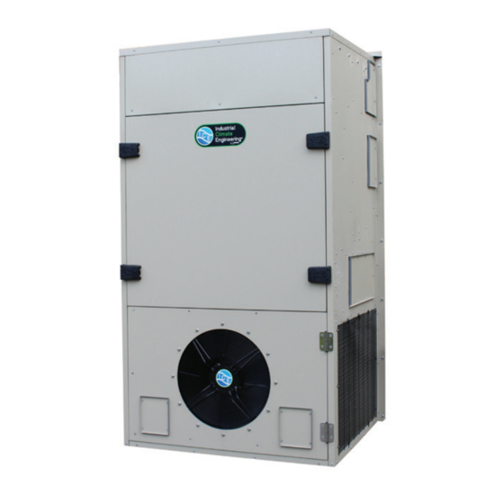
Vertical Air Conditioners
ICE CFA1120A-3360A & CGA3180A I&O Manual 03/2021 Rev.5
CFA1120A
, Inc.
®
Advertisement
Table of Contents
Troubleshooting

Related Manuals for Airxcel ICE CFA1120A


Summary of Contents for Airxcel ICE CFA1120A
-
Page 1: Table Of Contents
P.O. Box 5104 • Cordele, Georgia 31010 2002 Hoover St. • Cordele, Georgia 31015 (229) 273-9558 • Fax (229) 273-5154 E-mail: icesales@airxcel.com • Internet: www.acice.com The most current version of this manual can be found at www.acice.com. ICE CFA1120A-3360A & CGA3180A I&O Manual 03/2021 Rev.5... - Page 2 Used to point out helpful info that will result in improved installation, reliability or operation. IMPORTANT SPECIFICATIONS SUBJECT TO CHANGE WITHOUT NOTICE. © 03/2021 Industrial Climate Engineering™ Division of Airxcel , Inc. ™ ICE CFA1120A-3360A & CGA3180A I&O Manual 03/2021 Rev.5...
- Page 3 Porting and Duct Work ..........................26 Top Flange Installation ..........................26 Installing the Lifting Brackets ........................27 Mounting the Unit ..........................27 Electrical Connections ...........................28 Chapter 4 Start-Up Check-Out of Cooling Cycle .........................32 Check-Out of Heating Cycle ........................32 ICE CFA1120A-3360A & CGA3180A I&O Manual 03/2021 Rev.5...
- Page 4 MODBUS Network Address DIP Swith Positions ..............17 Table 6a. MODBUS Discrete Registers ....................21 Table 6b. MODBUS Registers........................22 Table 7 Minimum Clearances ........................ 24 Table 8 Voltage Limitations ........................24 ICE CFA1120A-3360A & CGA3180A I&O Manual 03/2021 Rev.5...
-
Page 5: Chapter 1 Description
ICE CFA & CGA units are designed for easy installation and service. Major components are accessible for service beneath external panels. All units have internal disconnects. Depending upon state and local code requirements, this feature may eliminate the need for an external breaker or disconnect. ICE CFA1120A-3360A & CGA3180A I&O Manual 03/2021 Rev.5... -
Page 6: Model Identification
Note: Follow local codes and standards when designing duct runs to deliver the required airflow. Minimize noise and excessive pressure drops caused by duct aspect ratio changes, bends, dampers and outlet grilles in duct runs. ICE CFA1120A-3360A & CGA3180A I&O Manual 03/2021 Rev.5... -
Page 7: General Operation
Cold liquid refrigerant passing through the evaporator is boiled into gas by heat removed from the air. The warmed refrigerant gas enters the compressor where its temperature and ICE CFA1120A-3360A & CGA3180A I&O Manual 03/2021 Rev.5... - Page 8 A wall-mounted thermostat controls the heating cycle of models which incorporate resistance heating elements. On a call for heat, the thermostat closes the heat relay to energize the indoor fan and the resistance elements. ICE CFA1120A-3360A & CGA3180A I&O Manual 03/2021 Rev.5...
-
Page 9: Optional Controls And Packages
Power must be applied to the unit for 24 hours before starting the compressor. The condenser (outside fan) motor is energized by the same contactor. The indoor evaporator fan motor is controlled by the fan purge on the electronic control board. ICE CFA1120A-3360A & CGA3180A I&O Manual 03/2021 Rev.5... -
Page 10: Figure 1A. Typical Electrical Schematics For Single Compressor Units
Figure 1a. Typical Electrical Schematic for Single Compressor Units ICE CFA1120A-3360A & CGA3180A I&O Manual 03/2021 Rev.5... -
Page 11: Figure 1B. Typical Electrical Schematics For Dual Compressor Units
Figure 1b. Typical Electrical Schematic for Dual Compressor Units ICE CFA1120A-3360A & CGA3180A I&O Manual 03/2021 Rev.5... -
Page 12: Chapter 2 Electronic Control Board
Lockout contacts are also provided along with the alarms being transferred via MODBUS. This chapter provides the necessary information for installing and operating the ICE PCB. The diagram below identifies the inputs, outputs and connections for the ICE PCB. ICE CFA1120A-3360A & CGA3180A I&O Manual 03/2021 Rev.5... -
Page 13: Installation And Replacement
Low pressure switch has opened twice Status 2 3 Blinks Freeze stat (optional) - Indoor coil temperature is below 35°F (1°C) Continuous Flash of Both LEDs Insufficient voltage to the board. Less than 20 Volts ICE CFA1120A-3360A & CGA3180A I&O Manual 03/2021 Rev.5... -
Page 14: Figure 2A. Setting The Speed For The Y1 And Y2 Operation For Indoor Motor
Use the potentiometer marked “IBM SPEED” to set the required speed. Bridge Jumper Position For Setting Y2 Speed IBM SPEED Potentiometer Figure 2b. Second Stage Cooling Speed ICE CFA1120A-3360A & CGA3180A I&O Manual 03/2021 Rev.5... -
Page 15: Figure 3. Output Termination For Indoor Motor Control Signal
Outdoor Motor PWM Signal Output. One Wire Connected to “GND” and the Other Connected to “PWM” Outdoor Motor 0-10V Signal Output. One Wire Connected to “GND” and the Other Connected to “0-10V” Figure 5. Output Termination for Outdoor Motor Control Signal ICE CFA1120A-3360A & CGA3180A I&O Manual 03/2021 Rev.5... -
Page 16: Figure 6. Communications Setup
MODBUS Network Address DIP switches. See Addressing Table Baud Rate - 19200 BPS: Between Upper and Middle Pin Baud Rate - 9600 BPS: Between Lower and Middle Pin Figure 6. Communications SetUp ICE CFA1120A-3360A & CGA3180A I&O Manual 03/2021 Rev.5... -
Page 17: Sequence Of Operation
5.1 High Pressure Lockout 5.2 Low Pressure Lockout 5.3 Low Voltage 5.4 Anti-short Cycle 6.0 Additional Features 6.1 MODBUS communication 6.2 Modulating Head Pressure Control 6.3 Freeze Stat Operation 6.4 Onboard Thermostat ICE CFA1120A-3360A & CGA3180A I&O Manual 03/2021 Rev.5... - Page 18 “Y1” speed setting on the board or via MODBUS. It also outputs a request dependent (based on FCC IN) control signal for the Outdoor Fan Motor. In Stage 1 Cooling operation, the compressor ICE CFA1120A-3360A & CGA3180A I&O Manual 03/2021 Rev.5...
- Page 19 “FCC IN” input is High. The board continues to produce these outputs until the Dehumidification request is dropped. Once this request is dropped, the Indoor Fan Motor continues to run for 90 seconds. ICE CFA1120A-3360A & CGA3180A I&O Manual 03/2021 Rev.5...
- Page 20 The sequence of operation is the same as described above for the various operation, but Indoor Motor speeds for various operation, Outdoor Motor Speed, Heating Setpoint and Cooling Setpoint (if applicable) has to be configured via MODBUS. See MODBUS register tables at the end of this section. ICE CFA1120A-3360A & CGA3180A I&O Manual 03/2021 Rev.5...
-
Page 21: Table 6A. Modbus Discrete Registers
0 = Off, 1 = Energized 0 = Modbus only Enables or disables reading the thermostat inputs in Modbus 1 Bit 1 = Read thermostat Inputs mode Default is 0 Table 6a. MODBUS Discrete Registers ICE CFA1120A-3360A & CGA3180A I&O Manual 03/2021 Rev.5... -
Page 22: Table 6B. Modbus Registers
12 = Future Use 13 = Freeze Fault 1 14 = Freeze Fault 2 15 = Y1 Locked Out 16 = Y2 Locked Out 17 = Low Voltage Table 6b. MODBUS Registers ICE CFA1120A-3360A & CGA3180A I&O Manual 03/2021 Rev.5... -
Page 23: Chapter 3 Installation
D) When installing multiple units, please note the recommended clearances noted in Table 4. CAUTION CFA3180, 3240, 3300, 3360 & CGA3180 units require additional support. The mounting flanges alone are not adequate. ICE CFA1120A-3360A & CGA3180A I&O Manual 03/2021 Rev.5... -
Page 24: Installation Materials
The bracket is shipped attached to the top of the unit. Before installing the unit, remove the bracket and reattach as described in Section 2.5 ICE CFA1120A-3360A & CGA3180A I&O Manual 03/2021 Rev.5... - Page 25 • High voltage wire, sized to handle the MCA (minimum circuit ampacity) listed on the data plate. • Over-Current Protection Device sized in accordance with the MFS (maximum fuse size) listed on the unit data plate. ICE CFA1120A-3360A & CGA3180A I&O Manual 03/2021 Rev.5...
-
Page 26: Porting And Duct Work
Remove the 4 screws in these holes and use these screws to attach the top flange to the air conditioner. 3. Apply a bead of silicone sealer on the wall side of the bottom support brackets on the unit. Circle the mounting holes with the silicone bead. ICE CFA1120A-3360A & CGA3180A I&O Manual 03/2021 Rev.5... -
Page 27: Installing The Lifting Brackets
7. Check the fit of each sleeve to its mating flange for possible air leaks. Apply silicone sealer to close any gaps. Install the air return and supply grilles. ICE CFA1120A-3360A & CGA3180A I&O Manual 03/2021 Rev.5... -
Page 28: Electrical Connections
Verification of proper rotation is made by observing that the suction pressure drops and the discharge pressure rises when the compressor is energized. An alternate method of verification for self contained system with small critical refrigerant charges, where ICE CFA1120A-3360A & CGA3180A I&O Manual 03/2021 Rev.5... - Page 29 Insulate the orange lead. CAUTION The external breaker(s) that provide power to the air conditioner must be sized per the maximum Fuse Size (MFS) shown on the Unit's data label. ICE CFA1120A-3360A & CGA3180A I&O Manual 03/2021 Rev.5...
- Page 30 CommStat Touch Lead/Lag HVAC Controller (See Figure 4b) The CommStat Touch telecom controller with a touch screen interface is designed to allow remote control and monitoring of ICE air conditioners with single or 2-stage compressors in a shelter ICE CFA1120A-3360A & CGA3180A I&O Manual 03/2021 Rev.5...
-
Page 31: Figure 9. Thermostat Connection Diagram
HVAC configuration. See the CommStat Touch PDS for more details. ICE SIMPLE COMFORT THERMOSTAT CONNECTION DIAGRAM Figure 9. Thermostat Connection Diagram ICE CFA1120A-3360A & CGA3180A I&O Manual 03/2021 Rev.5... -
Page 32: Chapter 4 Start-Up
1. Raise the heating set point temperature to a setting which is higher than the ambient temperature. The fan and electric heat should immediately cycle on. 2. Move the system switch to the "OFF" position. All functions should stop. ICE CFA1120A-3360A & CGA3180A I&O Manual 03/2021 Rev.5... -
Page 33: Chapter 5 Troubleshooting
Use refrigeration goggles when servicing the refrigeration circuit. WARNING The refrigerant circuit has hot surfaces, and the electrical voltages inside of the unit may be hazardous or lethal. SERVICE MAY BE PERFORMED ONLY BY QUALIFIED AND EXPERIENCED PERSONS. ICE CFA1120A-3360A & CGA3180A I&O Manual 03/2021 Rev.5... -
Page 34: Failure Symptoms Guide
3. Check relay for proper operation. Replace if defective. Compressor Troubleshooting NOTE: It is important to rule out other component failures before condemning the compressor. The following electrical tests will aid diagnosis: ICE CFA1120A-3360A & CGA3180A I&O Manual 03/2021 Rev.5... -
Page 35: Control Board Diagnosis
The unit must be in the cooling mode (compressor contactor Closed) before a fault condition can occur. ICE CFA1120A-3360A & CGA3180A I&O Manual 03/2021 Rev.5... -
Page 36: Chapter 6 Maintenance
Some solvents can cause the drain pan to corrode. Lubrication The condenser fan motor(s) and the evaporator blower motor(s) never require oiling. ICE CFA1120A-3360A & CGA3180A I&O Manual 03/2021 Rev.5... -
Page 37: Chapter 7 Warranty
THIS WARRANTY GIVES YOU SPECIFIC LEGAL RIGHTS, AND YOU MAY ALSO HAVE OTHER RIGHTS WHICH VARY FROM STATE-TO- STATE. Some states do not allow limitations or exclusions, so the above limitations and exclusions may not apply to you. ICE CFA1120A-3360A & CGA3180A I&O Manual 03/2021 Rev.5... -
Page 38: Chapter 8 Start-Up Checklist
❒Yes ❒No If unit has a crankcase heater, has it been energized for 24 hours? ❒Yes ❒No On a 208/230 v. units is control transformer (24 AC) wired for correct voltage? ❒Yes ❒No ICE CFA1120A-3360A & CGA3180A I&O Manual 03/2021 Rev.5... - Page 39 L1 & L3 = 243 Volts = 717 / 3 = 239 Average Voltage L2 & L3 = 233 Volts 239 - 233 = 6 100 x 6/239 =2.5% Voltage Unbalance Three phase units only check fan & compressor rotation. ICE CFA1120A-3360A & CGA3180A I&O Manual 03/2021 Rev.5...
- Page 40 Measured Line to Line Volts L1&L2_______V. L1&L3 ________V. L2&L3______V. (L1&L2 + L1&L3 + L2&L3)/3 = Avg. Voltage = _______________ Max. Deviation from avg. voltage = ______________volts Voltage imbalance = (100 x Max. Deviation)/avg. Voltage = ___________% ICE CFA1120A-3360A & CGA3180A I&O Manual 03/2021 Rev.5...
- Page 41 Evap. Leaving Air WB Temp ________ ________ Compressor Amps (L1) ________ ________ Compressor Amps (L2) ________ ________ Compressor Amps (L3) ________ ________ Notes: _________________________________________________________________________ _________________________________________________________________________ _________________________________________________________________________ _________________________________________________________________________ _________________________________________________________________________ _________________________________________________________________________ _________________________________________________________________________ _________________________________________________________________________ _________________________________________________________________________ _________________________________________________________________________ _________________________________________________________________________ _________________________________________________________________________ ICE CFA1120A-3360A & CGA3180A I&O Manual 03/2021 Rev.5...
-
Page 42: Appendix A Fresh Air Damper Installation
Appendix A Fresh Air Damper Installation ICE CFA1120A-3360A & CGA3180A I&O Manual 03/2021 Rev.5... - Page 43 15% of rated air flow of fresh air, in 5% increments. The hood is shipped from the factory in the closed position (no fresh air). To provide fresh air, remove the two screws on either side of the hood and reposition as desired. Fresh Air Hood Damper ICE CFA1120A-3360A & CGA3180A I&O Manual 03/2021 Rev.5...
-
Page 44: Exhaust Hood Installation
D. SCREW INTO PLACE WITH SHEET METAL SCREWS PROVIDED E. ADD SILICONE BEAD AROUND THE TWO SIDES AND REAR OF THE HOOD ASSY NOTE: CFA1120A/1150A/3150A UNITS ARE A DIFFERENT CABINET TO CFA3180A-3240A BUT DAMPER INSTALLATION PROCEDURE IS THE SAME. ICE CFA1120A-3360A & CGA3180A I&O Manual 03/2021 Rev.5...
Need help?
Do you have a question about the ICE CFA1120A and is the answer not in the manual?
Questions and answers