Table of Contents
Advertisement
Installation & Operation Manual
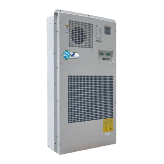
Cabinet Climate Control Combo Unit
Air Conditioner with Heat Exchanger
Models HC2010 & HC3012
Industrial Climate Engineering
Division of AIRXCEL
, Inc.
®
®
P.O. Box 5104 • Cordele, Georgia 31010
2002 Hoover St. • Cordele, Georgia 31015
(229) 273-9558 • Fax (229) 273-5154
E-mail: icesales@airxcel.com • Internet: www.acice.com
The most current version of this manual can
1
ICE A/C & HEX Combo Unit I&O Manual 07/2020 Rev.1
be found at www.acice.com.
Part Number 03816
Advertisement
Table of Contents

Related Manuals for Airxcel ICE HC2010


Summary of Contents for Airxcel ICE HC2010
- Page 1 P.O. Box 5104 • Cordele, Georgia 31010 2002 Hoover St. • Cordele, Georgia 31015 (229) 273-9558 • Fax (229) 273-5154 E-mail: icesales@airxcel.com • Internet: www.acice.com The most current version of this manual can ICE A/C & HEX Combo Unit I&O Manual 07/2020 Rev.1 be found at www.acice.com.
- Page 2 Used to point out helpful suggestions that will result in improved IMPORTANT installation, reliability or operation. SPECIFICATIONS SUBJECT TO CHANGE WITHOUT NOTICE. © 04/2019 Industrial Climate Engineering Div. Airxcel , Inc. ® ™ ICE A/C & HEX Combo Unit I&O Manual 07/2020 Rev.1...
-
Page 3: Table Of Contents
WARNING • If the information in these instructions are not followed exactly, a fire may result causing property damage, personal injury or loss of life. • Read all instructions carefully prior to beginning the installation. Do not begin installation if you do not understand any of the instructions. •... -
Page 4: Chapter 1: Description & Specifications
Chapter 1: Description & Specifications 1.1 Foreword Note: All operation of this unit shall be performed by qualified persons such as engineers and technicians. This manual shall only be used as the guide for the installation and operation of the ICE HC Series Combination Air Conditioner and Heat Exchanger Cabinet Climate Control Units. -
Page 5: Features
Note: Please refer to the unit data label for the power input. Application limitation Ambient temperature: 5ºF~131ºF (-15ºC~55ºC) Rated conditions: L35L35 The purpose of this air conditioner is controlling the operation temperature in the range of 5ºF~131ºF (-15ºC~55ºC) for the equipment in the cabinet or base. 1.3 Features •... -
Page 6: Preparation Before Installing
2.2 Preparation Before Installing Please make note of the following items before installation of the HC Series Combo Unit: • Ensure the correct installation of the equipment inside the cabinet. For example, any obstruction to the internal cycle air inlet and outlet of the air conditioner should be avoided. -
Page 7: Electrical Installation
2.4 Electrical Installation The electrical installation of the air conditioner includes: 1. Make sure that the supply power is OFF. 2. Connect the power cable and the input terminal according to the schematic diagram for power terminal, and tighten the screws. 3. -
Page 8: Installation Checklist
Monitoring Output: The unit’s RS485 communication cable adopts RJ45 port. Alarm Output: The unit alarm provides the dry contact normally close output. When faults occur, the dry contact will open. Contact capacity: resistive load 5A@30VDC/5A@277VAC. Please refer to Figure 3 for wiring diagram. 2.6 Installation Checklist Use the following checklist when the electrical connections and the Combo Unit installation are completed. -
Page 9: Operating Control Mode
3.2 Operating control mode 3.2.1 Cooling Control Cooling startup point = cooling stop point + cooling sensitivity. When the cabinet internal temperature exceeds the cooling startup point, cooling will start; when the cabinet internal temperature is lower than the cooling stop point, cooling will stop. Parameter Default Value Setting Range Units Description The temperature point at... - Page 10 Figure 5. Sample Alarm If the alarm hasn’t been cleared, the alarm information will be still visible, until the alarm has been eliminated. And you can check the alarm statistics through entering the alarm menu showed as Figure 7. Recovery Alarm Parameter Value/...
-
Page 11: Monitoring
Recovery Alarm Parameter Value/ Units Description Output Value Remedy Energy-saving is started when the Change cabinet internal External Temp. value external Temp. exceeds the Out.Ts.Fault is beyond sensor Temp. setting point, and checking range sensor compressor runs as normal logic, and upload protocol Condenser Temp is Stop compressor... - Page 12 ON/OFF ENTER Figure 6. Control Interface ON/OFF: ON/OFF Button, (long press this button, about 4s) this can be used to turn on/off the unit. Up Button, which is used to select the previous record/menu or increase the setting value (password only). Down button, which is used to select the next record/menu or decrease the setting value (password only).
-
Page 13: Chapter 4: Maintenance
Figure 7. Menu Structure Note: The above diagram is unit menu structure, not the factory setting. Chapter 4: Maintenance WARNING All maintenance shall be performed by qualified persons. Always disconnect the power, communication and alarm output cables from the Combo Unit before any maintenance and do not reconnect them until the maintenance is completed. -
Page 14: Daily Maintenance
4.1 Daily Maintenance Check Item Step Description Maintenance Cycle Wiring Visually check if any wiring is loose 12 months Turn the fan to check if it is smooth and if Fan Abnormalities 12 months there is any abnormal noise Visually check if the drainage outlet is Drainage Pipe 6 months blocked... -
Page 15: Chapter 5: Troubleshooting
Chapter 5: Troubleshooting 5.1 Troubleshooting Guide Symptom Possible Cause Solution Open circuit or short Check the open circuit or short circuit point, and circuit maintain the main power supply Unit Doesn’t Start Controller failure Replace controller Terminal is loose Check whether the connecting terminal is loose. Check the DC input power voltage, whether the Power failure voltage is in the range... -
Page 16: Chapter 6: Model Identification
Chapter 6: Model Identification 6.1 Model Identification The date of manufacture and serial number on the barcode is showed as follows: The first 13 bit (M019019000800) is the manufacture definition. The value of 14~18 bit (13701) stands for the date of manufacture: July 01, 2013 (A/B/C: October/November/December). -
Page 17: Chapter 7: Technical Parameters
Chapter 7: Technical Parameters 7.1 HC2010 Dimensional Drawings FRONT VIEW ISOMETRIC VIEW (561) (61) (101) (194) (185) RETURN (284) (194) (1001) SUPPLY (322) (10) (505) (450) (510) (10) (235) Ø (150) (10) (94) (406) (43) (545) BOTTOM VIEW (460) (130) (447) (984) (800) -
Page 18: Hc3012 Dimensional Drawings
7.1 HC3012 Dimensional Drawings (530) (250) (550) (64) (200) (200) (95) (194) (182) (60) (78) (127) RETURN (208) (200) (194) (56) (200) (113) (598) (200) (1300) (1350) (1330) (1350) (394) (200) (97) SUPPLY (406) (200) (206) (200) (202) (75) (183) (62) (6x10) FRONT VIEW...
Need help?
Do you have a question about the ICE HC2010 and is the answer not in the manual?
Questions and answers