Table of Contents
Advertisement
Installation & Operation Manual
DC Powered Cabinet
Climate Control Air Conditioner
Models DC03HDNC1U, DC05CDNC1U/DC05HDNC1U, DC10HDNC1U, DC20HDNC1U & DC30HDNC1U
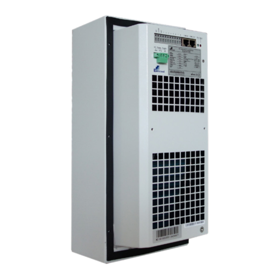
DC03HDNC1U
Industrial Climate Engineering
Division of AIRXCEL
, Inc.
®
®
P.O. Box 5104 • Cordele, Georgia 31010
2002 Hoover St. • Cordele, Georgia 31015
(229) 273-9558 • Fax (229) 273-5154
E-mail: icesales@airxcel.com • Internet: www.acice.com
The most current version of this manual can
1
ICE by Envicool DC Cabinet Cooler I&O Manual
be found at www.acice.com.
08/2020 Rev.7
Manual Part Number 03718
Advertisement
Table of Contents

Related Manuals for Airxcel ICE DC03HDNC1U


Summary of Contents for Airxcel ICE DC03HDNC1U
- Page 1 P.O. Box 5104 • Cordele, Georgia 31010 2002 Hoover St. • Cordele, Georgia 31015 (229) 273-9558 • Fax (229) 273-5154 E-mail: icesales@airxcel.com • Internet: www.acice.com The most current version of this manual can ICE by Envicool DC Cabinet Cooler I&O Manual be found at www.acice.com.
- Page 2 Used to point out helpful suggestions that will result in improved IMPORTANT installation, reliability or operation. SPECIFICATIONS SUBJECT TO CHANGE WITHOUT NOTICE. © 08/2020 Industrial Climate Engineering Div. Airxcel , Inc. ® ™ ICE by Envicool DC Cabinet Cooler I&O Manual...
-
Page 3: Table Of Contents
WARNING • If the information in these instructions are not followed exactly, a fire may result causing property damage, personal injury or loss of life. • Read all instructions carefully prior to beginning the installation. Do not begin installation if you do not understand any of the instructions. •... -
Page 4: Chapter 1: Description & Specifications
This manual shall only be used as the guide for the installation and operation of the ICE DC03HDNC1U, DC05CDNC1U, DC05HDNC1U & DC10HDNC1U Cabinet Air Conditioners. It introduces the functions and regular maintenances of the unit. 1.2 General Description This air conditioner is a cooling product developed for the telecom industry when DC power is preferred for operating the air conditioner. -
Page 5: Standards
1.4 Standards Standard Description GB/T 17626.7-1998 EMC GB4706.1 Safety of household appliances or similar electric appliance GB4798.1 Environmental conditions existing in the application of electric and electronic product – Storage Environmental conditions existing in the application of electric GB4798.2 and electronic product – Transportation GB4798.3 Environmental conditions existing in the application of electric and electronic product –... - Page 6 Figure 2a. DC03HDNC1U Schematic Diagram for Mechanical Installation Figure 2b. DC05CDNC1U Schematic Diagram for Mechanical Installation ICE by Envicool DC Cabinet Cooler I&O Manual 08/2020 Rev.7...
- Page 7 Figure 2c. DC05HDNC1U Schematic Diagram for Mechanical Installation Figure 2d. DC10HDNC1U, DC20HDNC1U & DC30HDNC1U Schematic Diagram for Mechanical Installation ICE by Envicool DC Cabinet Cooler I&O Manual 08/2020 Rev.7...
-
Page 8: Electrical Installation
Dimension Inches (mm) 4 (100) 19 ¾ (500) Figure 3a. DC03HDNC1U Figure 3b. DC10HDNC1U - DC30HDNC1U Minimum Clearances Minimum Clearances 2.4 Electrical Installation The electrical installation of the air conditioner includes: • Connecting the power cables • Connecting the communication & alarm output cables IMPORTANT All the electrical connections should comply with the standards of the national and local electrical codes. -
Page 9: Wiring Diagram & Electrical Connections
Select proper wire diameter and circuit protection device according to the air conditioner data label and technical parameters. Perform the electrical connection in accordance with the following steps: 1. Make sure that the air conditioner power is disconnected. 2. Connect the power cable to the input terminal according to the schematic diagram for power terminal. -
Page 10: Installation Check List
2.6 Installation Check List Use the following checklist when the electrical connection and the air conditioner installation are completed. H05VV-F 3×1.5mm² 1. There is no obvious obstacle near the internal cycle air inlet and outlet of the air conditioner. 2. The air conditioner is installed vertically and all the installation screws are tightened. -
Page 11: Component Control Mode
Parameter Default Value Setting Range Units Set Point Description Heating The temperature point of the [10 ~ 20] ºC Stop Point heating stop. Heater The sensitivity of the [1 ~ 10] ºC Sensitivity temperature control. Table 3. Heating Set Point Parameters 3.2.3 Component Control Mode 1. -
Page 12: Alarms
3.5 Alarms The cabinet air conditioner provides the following alarm information. See Table 4 for alarm parameters and settings. Figure 6. Sample Alarm If the alarm hasn’t been recovered, the alarm information will be still on, until the alarm has been eliminated. And you can check the alarm statistics through entering the alarm menu shown as Figure 6. - Page 13 ON/OFF ENTER Figure 7. Control Interface ON/OFF: ON/OFF Button, (long press this button, about 4s) this can be used to turn on/off the unit. Up Button, which is used to select the previous record/menu or increase the setting value (password only). Down button, which is used to select the next record/menu or decrease the setting value (password only).
- Page 14 Note: This diagram is unit menu structure, not the real factory setting. Comments: • In1: Internal return temperature sensor1 • In2: Internal return temperature sensor2 • Out: External ambient temperature sensor • Tp: Evaporator coil temperature sensor • Te: Compressor exhaust pipe temperature sensor •...
-
Page 15: Chapter 4: Technical Parameters
Chapter 4: Technical Parameters 4.1 DC03HDNC1U Dimensional Drawings FRONT VIEW ISOMETRIC VIEW (181) 1 ½ (38) (104.5) RETURN (56) (66) (400) (10) 2 Drain Holes (45) Ø (1.5) SUPPLY (15) (113.5) (130) (96) (1.5) (10) (113.5) (168) BOTTOM VIEW (122) Ø... -
Page 16: Dc05Cdnc1U Dimensional Drawings
4.2 DC05CDNC1U Dimensional Drawings FRONT VIEW ISOMETRIC VIEW Ø (124) (256) (96.5) RETURN (256.5) (5.8) (5.8) SUPPLY (6.5) (96) (3.3) Equally Distributed (320) (254) (58) BOTTOM VIEW (6.5) Ø (170) (3.3) (11.3) (202) (5.6) Equally Distributed (245.5) (550) (550) Ø (129) (44) (157) -
Page 17: Dc05Hdnc1U Dimensional Drawings
4.3 DC05HDNC1U Dimensional Drawings FRONT VIEW ISOMETRIC VIEW Ø (96) (124) (96.5) RETURN (5.6) (6.5) (3.3) SUPPLY (117.6) (11.3) Equally Distributed (173.5) (320) RETURN (26) (300) BOTTOM VIEW (230) (245.5) (62) SUPPLY (170) Equally Distributed (202) Equally Distributed (550) (550) (200) (346.8) (157) -
Page 18: Dc10Hdnc1U Dimensional Drawings
4.4 DC10HDNC1U Dimensional Drawings FRONT VIEW ISOMETRIC VIEW (185.5) (58) (85) (136.5) (83) (135.6) (191) RETURN (783) SUPPLY (178) (200) (48.5) (134) (46.2) (370) (446) (393) (450) (483) Ø (18) BOTTOM VIEW (468) (200) (260) (35) (48.5) (380) (128) (370) (286) (212) (440) -
Page 19: Dc20Hdnc1U Dimensional Drawings
4.5 DC20HDNC1U Dimensional Drawings FRONT VIEW ISOMETRIC VIEW (56.5) (194) (185) (108) (61.5) (84) RETURN (108) (194) (63) (783) (201) SUPPLY (228.5) Ø (155) (10) (446) (392) (131) (366.5) (69) Ø (18) (483) (380) BOTTOM VIEW (260) (44) (286) (746) (50) (370) (212) -
Page 20: Dc30Hdnc1U Dimensional Drawings
4.6 DC30HDNC1U Dimensional Drawings FRONT VIEW ISOMETRIC VIEW (49.5) (194) (166) (56.5) (222) RETURN (194) (42) Ø (395) (783) (20) SUPPLY (32) (286) (42) Ø (18) (150) (116) (446) (451) (150) (370) (370) (61) (479) (468) BOTTOM VIEW (380) (260) (44) (291) (746) -
Page 21: Chapter 5: Internal Wiring
Chapter 5: Internal Wiring 5.1 Schematic Diagram for Internal Wiring (DC03HDNC1U) The installation instructions for appliances that are intended to be permanently connected to fixed wiring, and have a leakage current that may exceed 10mA, shall state that the installation of a residual current device (RCD) having a rated residual operating current not exceeding 30mA is advisable. -
Page 22: Chapter 6: Daily Maintenance
Chapter 6: Daily Maintenance WARNING All maintenance shall be performed by qualified professionals. Always disconnect the power, communication and alarm output cables from the air conditioner before any maintenance and do not reconnect them until the maintenance is completed. 6.1 Daily Maintenance To ensure the normal operation of the air conditioner, please perform regular mainte- nances for it by referring to Table 5.
Need help?
Do you have a question about the ICE DC03HDNC1U and is the answer not in the manual?
Questions and answers