Table of Contents
Advertisement
Quick Links
CEA1012A, CEA1020A, CEA1024A,
CEA1030A, CEA1036A, CEA1042A,
CEA1048A, CEA1060A
Description .......................................... 5
Electronic Control Board .................... 8
Installation ......................................... 29
Start-Up ............................................. 40
Troubleshooting ................................ 41
Maintenance ...................................... 44
Warranty ............................................ 45
Start-Up Checklist ............................. 46
Fresh Air Damper Installation .......... 50
This manual may include information for options and features which may not be
included on the unit being installed. Refer to the unit data label or Model Identification
to determine which features and options this unit is equipped with.
INSTALLER: Affix the instructions on the inside of the building adjacent to the thermostat.
END USER: Retain this manual for future reference.
Industrial Climate Engineering™ Division of AIRXCEL
The most current version of this manual can be found at www.acice.com.
P.O. Box 5104 • Cordele, Georgia 31010
2002 Hoover St. • Cordele, Georgia 31015
(229) 273-9558 • Fax (229) 273-5154
E-mail: icesales@airxcel.com • Internet: www.acice.com
Installation & Operation Manual
Vertical Wall Mount Air Conditioners
Models
CGA1012A, CGA1020A, CGA1024A,
CGA1030A, CGA1036A, CGA1042A,
CGA1048A, CGA1060A
IMPORTANT
Manufactured By:
ICE CEA/CGA1012-1060 Wall Mount AC I&O Manual 03/2021 Rev.1
CEA1036A
, Inc.
®
Advertisement
Table of Contents
Troubleshooting

Related Manuals for Airxcel CEA1012A


Summary of Contents for Airxcel CEA1012A
-
Page 1: Table Of Contents
INSTALLER: Affix the instructions on the inside of the building adjacent to the thermostat. END USER: Retain this manual for future reference. Manufactured By: Industrial Climate Engineering™ Division of AIRXCEL , Inc. ® P.O. Box 5104 • Cordele, Georgia 31010 2002 Hoover St. - Page 2 Used to point out helpful suggestions that will result in improved installation, reliability or IMPORTANT operation. AS PART OF THE ICE CONTINUOUS IMPROVEMENT PROGRAM, SPECIFICATIONS ARE SUBJECT TO CHANGE WITHOUT NOTICE. © 03/2021 Industrial Climate Engineering™ Division of Airxcel , Inc. ™ ICE CEA/CGA1012–1060 Wall Mount AC I&O Manual...
- Page 3 WARNING • If the information in these instructions are not followed exactly, a fire may result causing property damage, personal injury or loss of life. • Read all instructions carefully prior to beginning the installation. Do not begin installation if you do not understand any of the instructions. •...
- Page 4 Compressor Troubleshooting .........................42 Control Board Diagnosis ........................43 Chapter 6 Maintenance Scheduled Maintenance .........................44 Chapter 7 Warranty Airxcel Commercial Group Limited Product Warranty .................45 Chapter 8 Start-Up Check List Start-Up Check List ..........................46 Appendix A Installation Instructions for Field Installed Electric Heaters ................50 Illustrations Figure 1a.
-
Page 5: Chapter 1 Description
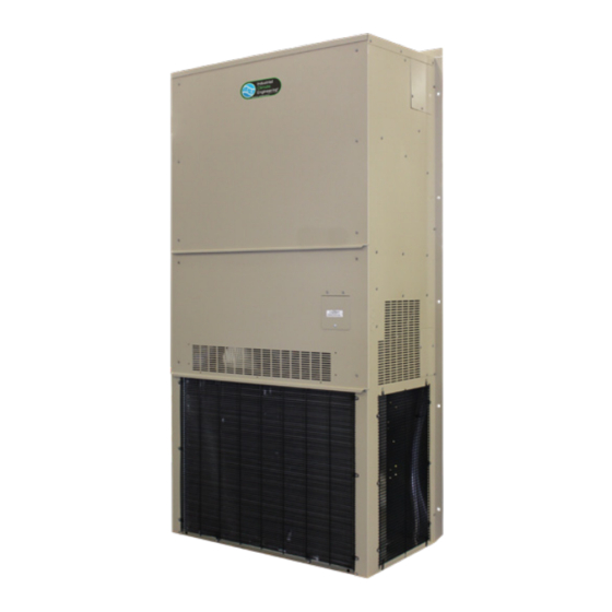
Chapter 1 Description & Specifications General Description The Industrial Climate Engineering (ICE) CEA and CGA are a series of vertical wall-mounted air conditioning systems that provide heating, cooling, and ventilation for electronic equipment shelters, process control centers, and other applications with high internal heat gains. The series includes multiple sizes and nominal cooling capacities from 12,000 to 60,000 BTUH. -
Page 6: Model Identification
Model Identification The model identification number is found on the data sticker. Rating plate located on side panel. Example Position Unit Designation/Family C = Industrial Climate Engineering (ICE) D = Dry Bulb Sensor Indoor Air Quality E = Dry Bulb Sensor w/Dirty Filter E = Standard Efficiency Energy Efficiency Ratio (EER) Features... -
Page 7: General Operation
Note: Follow local codes and standards when designing duct runs to deliver the required airflow. Minimize noise and excessive pressure drops caused by duct aspect ratio changes, bends, dampers and outlet grilles in duct runs. MODEL 0.10 0.15 0.20 0.25 0.30 0.40 0.50... -
Page 8: Optional Controls And Packages
temperature and pressure are increased. The hot refrigerant gas condenses to liquid as heat is transferred to outdoor air drawn across the condenser by the condenser fan. Liquid refrigerant is metered into the evaporator to repeat the cycle. Heating Mode A wall-mounted thermostat controls the heating cycle of models which incorporate resistance heating ele- ments. - Page 9 The Coastal Environmental Package includes: • Corrosion resistant fasteners • Sealed or partially sealed condenser fan motor • Protective coating applied to all exposed internal copper and metal in the condenser section • Protective coating on the condenser coil (Luvata Insitu®) contains ES2 (embedded stainless steel pigment) technology.
- Page 10 Three Phase Voltage Monitor Continuously measures the voltage of each of the three phases. The monitor separately senses low and high voltage, voltage unbalance including phase loss and phase reversal. An LED indicator glows when all voltages are acceptable. Automatically resets when voltages and phases are within operating tolerances.
-
Page 11: Electrical Operation
Electrical Operation The compressor and condenser fan are energized with a contactor controlled by a 24 VAC pilot signal. Some compressors incorporate an internal PTC crankcase heater that functions as long as primary power is available. The heater drives liquid refrigerant from the crankcase and prevents loss of lubrication caused by oil dilution. -
Page 12: Figure 1A. Typical Electrical Schematic - Cea/Cga (Non-Economizer)
Figure 1a. Typical Electrical Schematic - CEA/CGA (Non-Economizer) ICE CEA/CGA1012–1060 Wall Mount AC I&O Manual 03/2021 Rev.1... -
Page 13: Figure 1B. Typical Electrical Schematic - Cea/Cga (Economizer)
Figure 1b. Typical Electrical Schematic - CEA/CGA (Economizer) ICE CEA/CGA1012–1060 Wall Mount AC I&O Manual 03/2021 Rev.1... -
Page 14: Economizer Components
Economizer Components (Economizer Equipped Models Only) Damper Actuator: The damper actuator is a 24V motor that modulates the position of the damper blade. It is capable of driving a full 90 degrees within 90 seconds. The assembly has a spring return to close the damper during power outage. -
Page 15: Figure 2. Dry Bulb Sensor
Figure 2. Dry Bulb Sensor Once either the enthalpy or dry bulb sensor has determined that the outside air is suitable for cooling, the damper will open. The mixed air sensor will limit the air temperature delivered to the space by modulating the damper blade to mix warm indoor air with cooler outdoor air to provide a constant 50°F to 56°F (10°C to 13.5°C) Mixed Air Sensor:... -
Page 16: Figure 3. Enthalpy Sensor Temperature Control Points
Brand of Sensor Selection (W3 jumper) Honeywell enthalpy and dry bulb sensors are currently the only brand of sensors used in the air conditioners. Jumper W3 allows us to use alternative brands at a future date. On all current air conditioners, pins 1 &... -
Page 17: Figure 4. Economizer Control Board
1. W1 Economizer Sensor Selector 4. W3 Sensor Brand Selector 7. Minimum Position Potentiometer Jumper Pins 1 & 2 for enthalpy sensor Jumper Pins 1 & 2 for Honeywell sensor 0% to 100%. Factory setting is 50%. Jumper Pins 2 & 3 for dry bulb sensor Jumper Pins 2 &... -
Page 18: Chapter 2 Electronic Control Board
Chapter 2 Electronic Control Board Introduction WARNING Failure to observe the instructions contained in this document may result in personal injury and/or property damage and may void the warranty. Read this manual before installing, replacing or using this product. CEA and CGA models are equipped with ICE’s proprietary Printed Circuit Board (PCB), which sets the standard for the industry in flexibility, reliability and performance. -
Page 19: Installation And Replacement
Item Description Outdoor Motor Control Signal Output Indoor Motor Control Signal Output P 1/2- Pressure for Circuit 1 and Circuit 2 (Respectively) FS1 – Freeze Stat for Circuit 1 FS2 – Indoor Temperature Input Modbus Communication 3 Wire [A, B, COM] and Parallel RJ-11 Port Fan Cycle Control Input (only Applicable for EC Outdoor Motors) Hum –... -
Page 20: Figure 5A. Setting The Speed For The Y1 And Y2 Operation For Indoor Motor
Power The ICE PCB requires 24 VAC to operate. When the board is sufficiently powered, the “PWR” status light on the PCB illuminates “Green.” If there is insufficient power to the board, the “STATUS 1” and “STATUS 2” flashes continuously. Insufficient power to the board will result in no outputs being energized. -
Page 21: Figure 6. Output Termination For Indoor Motor Control Signal
Output Termination for Indoor Motor Control Signal Note: Follow data (wiring and signal control signal type) of the appropriate motor to setup the PCB Indoor Motor PWM Signal Output. Reference Wire Connected to “GND” and the Signal Connected to “PWM” Indoor Motor 0-10V Signal Output. -
Page 22: Figure 9. Communications Setup
Communication The ICE PCB comes equipped with MODBUS communication standard. There are 2 adjacent MODBUS communication ports connected in parallel. That is, both ports transmit the same information. The dif- ference between the ports is the physical connection. One port is for RS-485 (3 wire shielded cable is recommended) and the other port is RJ-11. -
Page 23: Sequence Of Operation
Address DIP Switch 1 DIP Switch 2 DIP Switch 3 DIP Switch 4 0 [Local Control] Table 5. MODBUS Network Address DIP Swith Positions Sequence of Operation IMPORTANT All equipment should go through the recommended commissioning/start up sequence to ensure safety and system reliability. This document is only valid if the system is used as intended. - Page 24 Equipment, devices and necessary system components are specified in the respective section. Note: 1. All inputs on the Controller go through a 5 seconds Time-On Delay to prevent nuisance request. Compressor Outputs go through 5 seconds staggered Time On delay to prevent nuisance tripping of breaker due to the inrush associated with these large inductive loads.
- Page 25 and the indoor fan remains on continuously but the outdoor fan cycles based on head pressure. The Fan Cycle Control Switch (Low Ambient Control Switch) closes at 400 PSIG to set the “FCC IN” input High which in turn outputs a speed proportional to the “OFM Speed” setting on the board or by MODBUS.
- Page 26 5.0 – Refrigeration Protection 5.1– High Pressure Lockout This condition describes the abnormal rise in Head Pressure pass the system acceptable limit of 660 PSI (+/-20PSI). The fault will only be active when the High-Pressure Switch (Normally Closed) opens during a request for Cooling. The first time this fault condition occurs, the system cuts the compressor off WITHOUT locking out.
-
Page 27: Table 6A. Modbus Discrete Registers
5.2 – Modulating Head Pressure Control A 10K Nominal NTC Thermistor is connected to the “P1” and “P2” inputs for circuit 1 and circuit 2 respectively. When this sensor is connected, the “FCC IN” is ignored and the thermistor value is used as the process variable when controlling the head pressure. -
Page 28: Table 6B. Modbus Registers
Registers: Read with Function Code 04, Write to RW or WO registers with Function Code 06 Description Size Data Format Heat Setpoint 16 Bit 45º-100º F Cool Setpoint 16 Bit 45º-100º F 0-20, 10 is default. Less Temperature Calibration 16 Bit than 10 is a negative offset, 11-20 is a positive offset 0-100, 80 is default. -
Page 29: Chapter 3 Installation
Chapter 3 Installation WARNING Failure to observe and follow Warnings and Cautions and these Instructions could result in death, bodily injury or property damage. Read this manual and follow its instructions and adhere to all Cautions and Warnings in the manual and on the unit. -
Page 30: Table 7 Minimum Clearances
element. This includes proper supply duct sizing, sufficient quantity of supply registers, and adequate return and filter areas. Duct work must be of correct material and must be properly insulated. Duct work must be constructed of galvanized steel with a minimum thickness of .019 inches. Duct work must be firmly attached, secured, and sealed to prevent air leakage. -
Page 31: Installation Materials
Installation Materials Installation Kits ICE CEA and CGA units are shipped with one 12 Ga. "L" shaped bottom bracket. If you have not yet unpacked the unit, follow the instructions in section 2.1. All units have built-in full length mounting flanges. -
Page 32: Porting And Duct Work
Additional Items Needed: Additional hardware and miscellaneous supplies (not furnished by ICE) are needed for installation. For example, the list below contains approximate quantities of items typically needed for mounting a unit on a wood frame wall structure. Concrete or fiberglass structures have different requirements. (10) 3/8"... -
Page 33: Figure 10. Back Panel Configuration For Cea/Cga1012 Air Conditioners
To change the back panel to use with a 28” x 19” (711 mm x 483 mm) opening, see the instructions below. Changing the back panel for use with a 19”W x 21”H (483 mm x 533 mm) wall opening. Note: Changing the back panel must be done before the unit is mounted on the enclosure. -
Page 34: Figure 11A. Fresh Air Hood Damper, Models 1024-1060
Wall Opening Dimensions of Wall Sleeve P/N of Wall Sleeve P/N of Grille 19”W x 21”H (483 mm x 533 mm) 17”W x 19”H (432 mm x 483 mm) S/12544 93195 & 93196 28”W x 19”H (711 mm x 483 mm) 26”W x 17”H (660 mm x 432 mm) S/01784 80681 Ducting... -
Page 35: Fresh Air Hood Installation
Bracket Installation 1. All models have built-in mounting flanges. 2. Apply a bead of silicone sealer on the wall side of the bottom support brackets on the unit. Circle the mounting holes with the silicone bead. 3. Refer to Figure 4. Attach the bottom support bracket to the wall using appropriate 3/8" diameter hardware. -
Page 36: Electrical Connections
COMBINATION SUPPLY & RETURN GRILLE WALL SLEEVE THRU WALL OPENING All units with electric heat MUST have one inch (25.4 mm) clearance on all four sides of the duct ange on the unit and on all four sides of the wall sleeve. The 1"... - Page 37 that the suction pressure drops and the discharge pressure rises when the compressor is energized. An alternate method of verification for self contained system with small critical refrigerant charges, where the installation of gauges may be objectionable, can be made by monitoring the temperature of the refrigerant lines at the compressor.
- Page 38 Dual Unit Phasing For applications where one controller operates two units, e.g., the CommStat 4 or CommStat Touch HVAC controller. Newer HVAC controllers sunch as the CommStat do not require unit phasing. However, if other devices are connected to the control system, phasing of the air conditioner is required. Earlier models; i.e., LL357, LL357A, LL357D2 require the unit to be properly phased.
-
Page 39: Figure 13A. Humidistat Wiring Details
Figure 13a. Humidistat Wiring to an ICE Air Conditioner with Reheat. Figure 13b. Thermostat Connection Diagram Figure 13c. CommStat 3 Wiring Diagram ICE CEA/CGA1012–1060 Wall Mount AC I&O Manual 03/2021 Rev.1... -
Page 40: Chapter 4 Start-Up
Chapter 4 Start-Up Check-Out of Cooling Cycle Important: Be sure that the crankcase heater (if used) has been energized for at least 24 hours before starting the unit(s). Double-check all electrical connections before applying power. ICE air conditioners with scroll compressors running on 3Ø power must be checked for proper rotation during the initial start-up. -
Page 41: Chapter 5 Troubleshooting
Chapter 5 Troubleshooting Overview A comprehensive understanding of the operation of the ICE air conditioner is a prerequisite to trouble- shooting. Please read the Chapter 1 for basic information about the unit. ICE air conditioners are thoroughly tested before they are shipped from the factory. Although unlikely, it is possible that a defect may escape undetected, or damage may have occurred during transportation. -
Page 42: Failure Symptoms Guide
Failure Symptoms Guide PROBLEM/SYMPTOM LIKELY CAUSE(S) CORRECTION A. Unit does not run. 1. Power supply problem. 1. Check power supply for adequate phase and voltage. Check wiring to unit and external breakers or fuses. NOTE: An internal anti-short-cycle 2. Tripped internal disconnect. 2. -
Page 43: Control Board Diagnosis
1. Start-Up Voltage: Measure the voltage at the compressor contactor during start-up. The voltage must exceed the minimum shown in Table 5, section 2.2, or compressor failure is likely. A low voltage condition must be corrected. 2. Running Amperage: Connect a clip-on type ammeter to the (common) lead to the compressor. Turn on the supply voltage and energize the unit. -
Page 44: Chapter 6 Maintenance
Chapter 6 Maintenance Scheduled Maintenance Airxcel Commercial Group strongly recommends that the air conditioner be serviced a minimum of twice a year – once prior to the heating season and once prior to the cooling season. At this time the filters, evaporator coil, condenser coil, the cabinet, and condensate drains should be serviced as described below. -
Page 45: Chapter 7 Warranty
Chapter 7 Warranty Airxcel Commercial Group Limited Product Warranty Marvair Inc., warrants its products to be free from defects in materials and workmanship under normal use to the original purchaser for the period of time in the table below. If any part of your product fails within 12 months from start-up, or 18 months from shipment from the factory, whichever comes first, Marvair, Inc. -
Page 46: Chapter 8 Start-Up Checklist
Chapter 8 Start-Up Check List The middle front panel provides access to the electrical/control box and to the filters. This panel has hinges on the left and right hand side. This panel should ONLY be opened by using the two hinges on the left side OR the two hinges on the right side. - Page 47 Condensate Section Has water been placed in drain pan to confirm proper drainage? ❒Yes ❒No Are correct filters in place? ❒Yes ❒No Refrigerant Piping If leaks are found, report any leaks to ICE Warranty Service Dept. C. Check Rated Voltage at Terminal Block for Imbalance before starting of Unit. ❒208/230V 1 Phase ❒208/230V 3 Phase ❒460V 3 Phase...
- Page 48 D. Heating Mode Check & Record Readings Circuit 1 Circuit 2 (if applicable) Room Temperature ________ ________ Outside Temperature ________ ________ Evap. Entering Air DB Temp ________ ________ Evap. Entering Air WB Temp ________ ________ Evap. Leaving Air DB Temp ________ ________ Evap.
- Page 49 After 10 minutes of compressor operation, record the following: Circuit 1 Circuit 2 (if applicable) Room Temperature ________ ________ Outside Temperature ________ ________ Suction Pressure ________ ________ Suction Line Temperature ________ ________ Discharge Pressure ________ ________ Discharge Line Temperature ________ ________ Entering Condenser Air ________...
-
Page 50: Appendix A Fresh Air Damper Installation
Note: The following instructions are for general guidance only. Due to the wide variety of installation possibilities, specific instructions will not be given. When in doubt, follow standard and accepted installation practices, or contact Airxcel Commercial Group for additional assistance. Wall Openings Measure the dimensions of the supply and return ports on the unit. - Page 51 WARNING ELECTRICAL SHOCK HAZARD Failure to follow safety warnings exactly could result in serious injury, death, and/or property damage. Turn off electrical power at fuse box or service panel BEFORE making any electrical connections and ensure a proper ground connection is made before connecting line voltage.
- Page 52 ICE CEA/CGA1012–1060 Wall Mount AC I&O Manual 03/2021 Rev.1...
Need help?
Do you have a question about the CEA1012A and is the answer not in the manual?
Questions and answers