Table of Contents
Advertisement
Available languages
Available languages
Quick Links
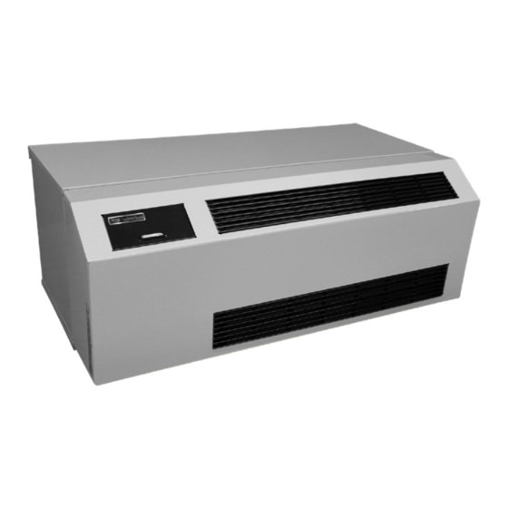
PACKAGED TERMINAL AIR CONDITIONER
MODELS: DYNA07AC • DYNA09AC • DYNA12AC • DYNA16AC
INSTALLATION, OPERATING AND SERVICE INSTRUCTIONS
This book contains instructions for installation and operation of your unit. Keep it in a safe place for ready reference.
Manufactured By:
Airxcel, Inc.
Suburban Applied Products
156 Seedling Drive.
Cordele, Georgia 31015
(229) 273-3636
www.SuburbanHVACproducts.com
If the information in these instructions are not followed exactly, a fire or explosion may result causing
property damage, personal injury or loss of life.
Do not store or use gasoline or other flammable vapors and liquids in the vicinity of this or any other appliance.
WHAT TO DO IF YOU SMELL GAS
• Do not try to light any appliance.
• Do not touch any electrical switch; do not use any phone in your building.
• Immediately call your gas supplier from a neighbor's phone. Follow the gas supplier's instructions.
• If you cannot reach a gas supplier, call the fire department.
Installation and service must be performed by a qualified installer, service agency or the gas supplier.
INSTALLER: Leave this manual with the appliance.
CONSUMER: Retain this manual for future reference.
Improper installation, adjustment, alteration, service or maintenance can cause property damage,
personal injury or loss of life. Refer to the installation instructions and/or owners manual provided with
this appliance. Installation and service must be performed by a qualified installer, service agency or
the gas supplier.
DynaLine3
OWNER'S MANUAL
Should you require further information, contact your dealer.
WARNING
WARNING
™
1
Suburban DynaLine Owner's Manual 04/2021 Rev.4
COMMERCIAL/INDUSTRIAL GROUP
Part Number 81758
Advertisement
Table of Contents

Related Manuals for Airxcel Suburban DynaLine3


Summary of Contents for Airxcel Suburban DynaLine3
- Page 1 This book contains instructions for installation and operation of your unit. Keep it in a safe place for ready reference. Should you require further information, contact your dealer. Manufactured By: Airxcel, Inc. Suburban Applied Products 156 Seedling Drive. Cordele, Georgia 31015 (229) 273-3636 www.SuburbanHVACproducts.com...
-
Page 2: Unit Specifications
FOREWORD You have just purchased a Suburban Packaged Terminal Air Conditioner. Models DYNA07AC, DYNA09AC, DYNA12AC and DYNA16AC are ETL (Intertek) certified under ANSI Z21.86-2016/CSA 2.32-2016/UL484-2014 Standards. To simplify the proper installation and to assure that the unit will operate in conformity with generally accepted safety regulations, it requires that you read carefully and fully understand the step-by-step instructions outlined in this manual. -
Page 3: Minimum Clearances To Combustible Construction
PRE-INSTALLATION TIPS AND CONSIDERATION MINIMUM OPERATIONAL CLEARANCES The following minimum outside clearance from rear grille must be maintained: Rear of unit to nearest obstruction - 36” Side of unit to nearest obstruction - 0” CAUTION This appliance should not be installed on or near adjacent walls with vinyl siding without first consulting with the manufacturer of the siding or cutting the siding away from the area around the appliance vent. - Page 4 HEADER HEADER (STEEL LINTEL IN BRICK CONSTRUCTION) (STEEL LINTEL IN BRICK CONSTRUCTION) 1" MIN. 1" MIN. 1" MIN. 1" MIN. 1" MIN. SURFACE OF FINISHED FLOOR FINISHED FLOOR WALL SLEEVE FRAMING DIMENSIONS SUB-FLOOR WALL SLEEVE FRAMING DIMENSIONS WALL SLEEVE FRAMING DIMENSIONS REAR GAS HOOK-UP WALL SLEEVE FRAMING DIMENSIONS FRONT GAS HOOK-UP...
- Page 5 - ( X" + Y" Y" = 14 X" SURFACE OF FINISHED INTERIOR WALL SURFACE OF FINISHED EXTERIOR WALL CABINET FRONT CAULK AROUND WALL SLEEVE X" REPRESENTS EITHER THE REAR GRILLE DIMENSION REQUIRED TO FLUSH SLEEVE TO FINISHED TRIM OR MOLDING, OR THE DISTANCE SLEEVE PROJECTS INTO ROOM MOUNTING HOLES AND SCREWS...
-
Page 6: Installation
INSTALLATION Before beginning the installation, it is suggested that the cabinet front and air filter be removed to avoid damage during installation of the unit. Cut an opening in the outside wall and frame to the minimum opening as illustrated in Figures 2 or 3. Refer to Table 1 for minimum clearances to obstruction. - Page 7 1" (MAX.) LONG SCREWS FOR SECURING ANGLES TO TOP & SIDES OF SLEEVE. WALL SLEEVE WINDOW OR WALL CAULK AROUND WALL SLEEVE CABINET FRONT REAR GRILLE WALL SLEEVE ANGLES & SCREWS 2 (MIN.) SUPPORTS (BY INSTALLER.) (BY INSTALLER) DO NOT PUT HOLES THROUGH OR DRIVE SCREWS INTO WALL SLEEVE BOTTOM! 1"...
-
Page 8: Operating Pressure
GRILL POSITION FOR VERTICAL AIR FLOW POSITION GRILLE POUR THERMOSTAT SWITCH: SLIDE #1 SWITCH FLUX D'AIR VERTICAL TO "ON", SWITCH #2 REMAINS IN "OFF" POSITION GRILL POSITION FOR HORIZONTAL AIR FLOW POSITION POUR GRILL FLUX D'AIR HORIZONTAL MODULE BOARD (LOCATED ON CONTROL PANEL) REMOTE THERMOSTAT TERMINAL BLOCK NOTE: THERE IS A 5/8"... - Page 9 All external wiring must comply with local codes or national electrical codes. It is recommended that the wiring be on a separate permanent line electrical circuit. The electrical circuit must be protected using dual 15 amp fuse or HACR type circuit breaker. In the U.S.A., the unit when installed, must be electrically grounded in accordance with local codes or, in the absence of local codes, with the latest edition of National Electrical Code ANSI/NFPA No.
- Page 10 If the main burner flame is sensed, the burner will remain on until the thermostat is satisfied. If the flame is not sensed, the gas valve closes and the ignition sequence automatically repeated two (2) times. If the burner does not light during this trial for ignition period, the unit will lock-out for one (1) hour and then re-set automatically.
- Page 11 Trouble Feature: When the sensor supervision is in a trouble condition (e.g. such as a sensor that has been tampered with, or the cell itself has prematurely dried out due to environmental conditions, etc.), the detector will send a trouble signal to the panel. The detector must then be replaced. The green LED turns off and the red LED blinks every minute when the detector is in trouble.
- Page 12 LIMITATIONS OF CARBON MONOXIDE (CO) DETECTORS Manufacturer recommends that carbon monoxide (CO) detectors be located throughout a protected premise following the recommendations of the current edition of the National Fire Protection Association Standard 720, National Fire Alarm Code (NFPA 720), manufacturer's recommendations, and state and local codes.
-
Page 13: Preventive Maintenance
Overload Protection - These units are equipped with an electrical safety overload which stops the compressor in the event of electrical overload. If repeated overload cycling occurs, call your dealer or a local repair agency equipped to service air conditioning equipment. DISPLAY PANEL CONTROL ROD (FRESH AIR VENT) - Page 14 Check all gas connections and gas controls (electrical valves, manual shut-off valves, regulators, etc.) for leaks. WELL DEFINED PATTERN This inspection should include a complete operational check of the unit including all electrical and mechanical components. BURNER OBSERVATION NOTE: If cabinet front was removed in order to inspect the unit and controls, it must be reinstalled prior to operating the unit. WINDOW You as the owner/user should inspect the unit periodically during the heating season.
-
Page 15: General Notes
Listed below are several safety related items that you should follow during the heating season to assure continued safe operation of the furnace. Never operate the unit if you smell gas. Do not assume that the smell of gas is normal. Any time you detect the odor of gas, it is to be considered life threatening and corrected immediately. -
Page 16: Wiring Diagrams
WIRING DIAGRAMS COMPRESSOR CONTACT COMPRESSOR PRESSURE CONTROLLER DE-ICER SWITCH N.C. SWITCH COMPRESSOR RELAY FLUE LIMIT HI-LIMIT PRESSURE CONDENSOR MOTOR CO DETECTOR CONTACT TEMP. SENSE ROOM GAS VALVE MOTOR FLAME PROBE EXHAUST MOTOR 24VAC 24V. CONT 230VAC VALVE POWER SUPPLY BOARD CO DETECTOR 230V 208V... - Page 17 Suburban DynaLine Owner's Manual 04/2021 Rev.4...
-
Page 18: Optional Accessories
OPTIONAL ACCESSORIES ALUMINUM GRILLE STOCK NO. 1625 REAR GRILLE INTRODUCTION The grille was specially designed for the DL3 Dynaline. Do not attempt to bend or alter the design of the grille or the venting system of the Dynaline unit. The grille will also work, as designed, for those models with rear gas hook-up. - Page 19 DL3 AIR DISCHARGE PACKAGE STOCK NO. K/10730 - ADAPTOR STOCK NO. K/10733 - EXTENSION STOCK NO. K/10734 - CONNECTOR INTRODUCTION This optional package allows for distribution of air into an adjacent zone requiring a controlled temperature. This assembly will discharge the conditioned air to either the right or left depending upon which end the cap is placed. (See Figures 20 and 21) This package, when installed on a DL3-0912 series cannot be lengthened.
- Page 20 Dynaline 3 Model Identification Example Position 012 = 12,000 020 = 18,000 Nominal Heat Input Unit Designation Dynaline 3™ 022 = 20,000 N = Natural Gas Fuel Type L = LP Gas 07 = 7,600 09 = 9,500 Gas Connection F = Front Nominal Cooling Capacity 12 = 11,500...
- Page 21 Suburban Applied Products by Marvair, Inc. Limited Product Warranty Marvair Inc., warrants its Suburban Applied Products to be free from defects in materials and workmanship under normal use to the original purchaser for the period of time in the table below. If any part of your Suburban AP product fails within 24 months from the date of the original start-up, Marvair will furnish without charge, EXW Cordele, Georgia, the required replacement part.
- Page 22 APPENDIX A MODULE BOARD AND DISPLAY BOARD REPLACEMENT INSTRUCTIONS ALL DL3 UNITS Suburban Applied Products is introducing an updated control board and display for the Dynaline DL3 models DYNA07AC, DYNA09AC DYNA12AC and DYNA16AC This is effective on production starting with serial number LH-F164074-0-12 produced on November 26, 2018.
- Page 23 Installation of this appliance must be made in accordance with the written instructions provided in the manual. No agent, representative or employee of Airxcel, Inc. - Suburban Division or other person has the authority to change, modify or waive any provision of the instructions contained in the manual or this instruction sheet.
- Page 24 Wiring Diagrams for DYNALINE Wiring Diagrams for DYNALINE ith serial numbers starting with letters (2016 and later) with serial numbers starting with letters (2016 and later) WITH Carbon Monoxide Detector WITHOUT Carbon Monoxide Detector COMPRESSOR COMPRESSOR CONTACT CONTACT COMPRESSOR COMPRESSOR PRESSURE PRESSURE CONTROLLER...
- Page 25 APPENDIX B SYSTEM FAULTS AND SERVICE MENU DESCRIPTION When a system fault is detected such as the HIGH LIMIT SWITCH OPEN, the DECIMAL POINT located in the lower right hand corner of the display will illuminate. When the fault is corrected or removed, the DECIMAL POINT will extinguish. The fault is logged into the microprocessor and can be recalled by the field service person.
- Page 26 FAULT CODES AND DESCRIPTIONS ( ALL DL3 UNITS) Fault # Fault Type Description Details The display will show “Lo” for an open circuit in sensor or wire and will show “Hi” for a shorted circuit in sensor or wire. If code 2 occurs, the THERMOSTAT Service System Indicator will stay ON until power is cycled.
- Page 27 Cette brochure contient des instructions concernant l'installation et le fonctionnement de l'apparell. Conserver cette brochure en lieu sûr pour pouvoir facilement la consulter. Pour d'autres renseignments, contracter is concessionnaire. Fabriqué par: Airxcel, Inc. Suburban Applied Products 156 Seedling Drive. Cordele, Georgia 31015 (229) 273-3636 www.SuburbanHVACproducts.com...
-
Page 28: Avant-Propos
AVANT-PROPOS Vous venez d’acheter un climatiseur autonome Suburban. Les modèles DYNA07AC, DYNA09AC, DYNA12AC et DYNA16AC sont ETL (Intertek) certifiés ANSI Z21.86-2016/CSA 2.32-2016 UL484-2014 de normalisation. Pour simplifier l’installation et garantir que l’appareil fonctionnera en conformité avec les règles de sécurité généralement acceptées, il est impératif que l’installateur lise attentivement et comprenne la totalité... -
Page 29: Planification De L'installation
PLANIFICATION DE L’INSTALLATION DÉGAGEMENTS DE SÉPARATION - VALEURS MINIMALES On doit ménager un dégagement minimum à l’extérieur par rapport à la grille arrière, comme suit: Entre l’arrière de l’appareil et la plus proche obstruction - 36 po Entre le côté de l’appareil et la plus proche obstruction - 0 po ATTENTION Cet appareil ne doit pas être installé... - Page 30 Lors de l’installation sous une fentre, l’installateur doit tenir compte du risque de perturbation de l’écoulement de l’air déchargé par des rideaux, et adopter les mesures appropriées pour éliminer ces perturbations. Lors de l’installation de la chemise murale au cours des phases préliminaires de la construction, l’installateur doit tenir compte de la pose ultérieure de panneaux de gypse ou autres finitions intérieures sur le mur.
- Page 31 Y" = 14 - ( X" + Y" X" SURFACE DE FINITION DU MUR INTÉRIEUR SURFACE DE FINITION DU MUR EXTÉRIEUR AVANT DE LA CAISSE CALFEUTRER AUTOUR DE LA GAINE MURALE X = DIMENSIONS NÉCESSAIRE GRILLE ARRIÉRE POUR QUE LA GAINE SOIT EN AFFLEUREMENT AVEC LA MOULURE OU LA GARNITURE DE FINITION, OU BIEN...
- Page 32 INSTALLATION Pour éviter toute détérioration au cours de l’installation de l’appareil, on suggère de déposer le panneau de façade de la caisse et le filtre à air avant d’entreprendre l’installation. Découper une ouverture dans le mur extérieur, et réaliser un encadrement adapté à l’ouverture minimale conformément aux illustrations de la figure 2 ou 3.
- Page 33 MISE EN GARDE Ne pas percer de trous dans le fond de la chemise murale. La cornière du fond est utilisée pour le support seulement, et on doit la fixer au mur. Fixer la chemise de garnissage mural au mur selon les indications de la figure 4 ou 5. Veiller à ce que la chemise murale soit d’aplomb (parallèle au sol, transversalement) et inclinée de 1/4 po dans la direction avant/arrière.
- Page 34 RACCORDEMENTS À LA CANALISATION DE GAZ Un raccord de 3/8 po NPT pour canalisation de gaz est installé sur l’appareil à l’usine. Calculer la taille de la tuyauterie selon le type de gaz et la longueur de la canalisation. Le Tableau 2 fournit une indication assez précise du diamètre de la canalisation à utiliser. Les débits cités dans la table sont exprimés en pi par heure.
-
Page 35: Instructions D'utilisation
Enlever l’afficheur; conserver les 5 vis pour réutilisation. (Voir la Figure 13) Acheminer le câblage depuis une source externe de 24 VCA, à travers le passe-fil qui se trouve à la base de l’appareil. Installer une cosse femelle isolée de ¼ po à l’extrémité de 2 conducteurs. Connecter les conducteurs sur les broches PWR DOWN de la carte du module. - Page 36 Lorsque la température sélectionnée par le thermostat s’est établie dans la pièce, la vanne d’admission de gaz se ferme. Le moteur d’admission d’air de combustion continue à fonctionner pendant une période de 20 secondes, puis s’arrète. Le ventilateur de circulation de l’air continue à fonctionner pendant environ 90 secondes avant de s’arrèter (ouverture d’un contacteur dans le circuit d’alimentation).
- Page 37 Caractéristique Trouble: Lorsque la surveillance de la sonde est dans un état de trouble (tel que par exemple un capteur qui a été altéré, ou la cellule elle-même a prématurément séché en raison de conditions environnementales, etc), le détecteur enverra un signal de panne à l'panneau. Le détecteur doit alors être remplacé.
- Page 38 Le monoxyde de carbone est un gaz hautement toxique qui est libéré lors de la combustion sont brûlés. Il est invisible, n'a pas d'odeur et est donc impossible à détecter par les sens humains. Dans des conditions normales dans une pièce où la combustion des combustibles appareils sont bien entretenus et correctement ventilés, la quantité...
-
Page 39: Entretien Préventif
ORGANES DE COMMANDE ET LEURS FONCTIONS Commutateur de limite - La fonction de ce contacteur de détection de limite est d’interrompre l’arrivée de gaz au brûleur principal si pour une raison quelconque une température supérieure à la limite de sécurité s’établit dans la section de chauffage. Des manoeuvres cycliques du contacteur n’indiquent pas toujours qu’il est défectueux. -
Page 40: Retrait Du Filtre
AVERTISSEMENT Déconnecter toujours l’alimentation électrique avant de nettoyer l’appareil ou d’effectuer des travaux d’entretien. Un technicien d’entretien qualifié devrait inspecter l’appareil chaque année avant la mise en marche du système de chauffage pour l’hiver. Accorder une attention particulière aux points suivants. Inspecter tous les joints. - Page 41 Le filtre peut être lavé dans une eau savonneuse et rincé à l’eau propre. Laisser le filtre sécher avant de le réinstaller dans l’appareil. Réinstaller le filtre. REMARQUE : NE JAMAIS UTILISER L’APPAREIL SANS FILTRE. Le serpentin d’évaporation ou le plateau de drainage pourraient comporter des restrictions.
-
Page 42: Notes Générales
Dynaline 3 Identification du modèle Exemple Position 012 = 12,000 020 = 18,000 Puissance thermique nominale Désignation d'unité Dynaline 3™ 022 = 20,000 N = Gaz naturel Type de carburant L = GPL 07 = 7,600 Capacité de refroidissement 09 = 9,500 Connexion de gaz F = De face nominale... -
Page 43: Schémas De Câblage
SCHÉMAS DE CÂBLAGE COMPRESSOR CONTACT COMPRESSOR PRESSURE CONTROLLER DE-ICER SWITCH N.C. SWITCH COMPRESSOR RELAY FLUE LIMIT HI-LIMIT PRESSURE CONDENSOR MOTOR CO DETECTOR CONTACT TEMP. SENSE ROOM GAS VALVE MOTOR FLAME PROBE EXHAUST MOTOR 24VAC 24V. CONT 230VAC VALVE POWER SUPPLY BOARD CO DETECTOR 230V 208V... - Page 44 Suburban DynaLine Owner's Manual 04/2021 Rev.4...
-
Page 45: Accessoires Facultatifs
ACCESSOIRES FACULTATIFS GRILLE D’ALUMINIUM PRODUIT N° 1625 GRILLE ARRIÈRE INTRODUCTION Cette grille a été conçue pour les modèles DL3 Dynaline. Ne pas tenter de courber ou modifier la grille ou le système de communication avec l’atmosphère de l’appareil Dynaline. La grille est également utilisable avec les modèles raccordés à la canalisation de gaz par l’arrière. - Page 46 SYSTÈME DE DÉCHARGE DE L’AIR - APPAREIL DL3 Produit n° K/10730 - Adaptateur • Produit n° K/10733 - Extension • Produit n° K/10734 - Connecteur INTRODUCTION Cet ensemble proposé en option permet la distribution de l’air dans une zone adjacente nécessitant un contrôle de la température. Cet ensemble décharge l’air chauffé...
- Page 47 Produits appliqués Suburban par Marvair, Inc. Garantie limitée du produit Marvair Inc., garantit ses produits Suburban Applied contre tout défaut de matériaux et de fabrication dans des conditions normales d'utilisation à l'acheteur d'origine pendant la période indiquée dans le tableau ci-dessous. Si une partie de votre produit Suburban AP tombe en panne dans les 24 mois à compter de la date de démarrage d'origine, Marvair fournira gratuitement, EXW Cordele, Géorgie, la pièce de rechange requise.
- Page 48 ANNEXE A CARTES DE MODULE ET D’AFFICHAGE INSTRUCTIONS DE REMPLACEMENT SUR TOUTES LES UNITÉS DL3 Suburban Applied Products lance des nouvelles cartes améliorées pour contrôle et affichage de ses Dynaline DL3, modèles DYNA07AC, DYNA09AC, DYNA12AC, DYNA16AC. Ce changement est appliqué en production à partir de l’unité N° de série LH-F164074-0-12 produite le 28 novembre 2018.
- Page 49 L’installation de cet appareil doit être faite en conformité avec les instructions écrites formulées dans le manuel. Aucun agent, représentant ou employé d’Airxcel, Inc. - Suburban Division, ni toute autre personne, n’a l’autorité de changer, modifier ou annuler une quelconque disposition des instructions contenues dans le manuel ou cette fiche d’instructions.
- Page 50 Wiring Diagrams for DYNALINE Wiring Diagrams for DYNALINE ith serial numbers starting with letters (2016 and later) with serial numbers starting with letters (2016 and later) WITH Carbon Monoxide Detector WITHOUT Carbon Monoxide Detector COMPRESSOR COMPRESSOR CONTACT CONTACT COMPRESSOR COMPRESSOR PRESSURE PRESSURE CONTROLLER...
- Page 51 ANNEXE B DÉFAUTS DU SYSTÈME ET DESCRIPTION DU MENU DE SERVICE Lorsqu'une anomalie du système est détectée, comme l'ouverture du commutateur de limite haute, le POINT DÉCIMAL situé dans le coin inférieur droit de l'écran s'allume. Lorsque le défaut est corrigé ou supprimé, le POINT DÉCIMAL s'éteint. Le défaut est enregistré dans le microprocesseur et peut être rappelé...
- Page 52 CODES DE DÉFAUT ET DESCRIPTIONS ( SUR TOUTES LES UNITÉS DL3) Faute Type de défaut La description Détails L'écran affichera «Lo» pour un circuit ouvert dans le capteur ou le fil et affichera «Hi» pour un court-circuit dans le capteur ou le fil. Si le code 2 se produit, l'indicateur du système de service restera allumé...
Need help?
Do you have a question about the Suburban DynaLine3 and is the answer not in the manual?
Questions and answers