Table of Contents
Advertisement
Quick Links
Chapter 1
Description ................................. 5
Chapter 2
Installation ............................... 14
Chapter 3
Start-Up ................................... 20
Chapter 4
Troubleshooting ....................... 21
Chapter 5
Maintenance ............................. 24
Chapter 6
Warranty .................................. 25
Chapter 7
Exploded View Parts List .......... 26
Industrial Climate Engineering™ Division of AIRXCEL
The most current version of this manual can be found at www.acice.com.
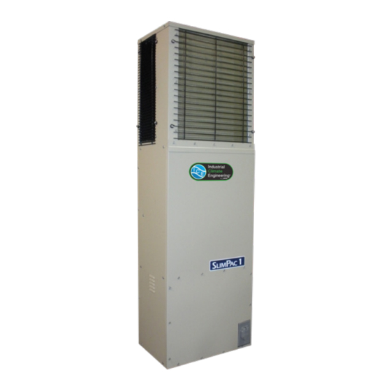
Model CFA1012A
P.O. Box 5104 • Cordele, Georgia 31010
2002 Hoover St. • Cordele, Georgia 31015
(229) 273-9558 • Fax (229) 273-5154
E-mail: icesales@airxcel.com • Internet: www.acice.com
Installation & Operation Manual
Vertical Air Conditioners
Manufactured By:
CFA1012A
, Inc.
®
ICE CFA1012A I&O Manual 01/2021 New
Advertisement
Table of Contents
Troubleshooting

Related Manuals for Airxcel Industrial Climate Engineering CFA1012A


Summary of Contents for Airxcel Industrial Climate Engineering CFA1012A
- Page 1 Warranty ........25 Chapter 7 Exploded View Parts List ..26 CFA1012A Manufactured By: Industrial Climate Engineering™ Division of AIRXCEL , Inc. ® P.O. Box 5104 • Cordele, Georgia 31010 2002 Hoover St. • Cordele, Georgia 31015 (229) 273-9558 • Fax (229) 273-5154 E-mail: icesales@airxcel.com •...
- Page 2 Failure to comply could result in minor personal injury and/or property damage. CAUTION Used to point out helpful info that will result in improved installation, reliability or operation. IMPORTANT SPECIFICATIONS SUBJECT TO CHANGE WITHOUT NOTICE. © 01/2021 Industrial Climate Engineering™ Div. Airxcel , Inc. ™ ICE CFA1012A I&O Manual 01/2021 New...
-
Page 3: Table Of Contents
Chapter 3 Start-Up Start-Up & Commissioning Checklist ....................18 Chapter 4 Troubleshooting Overview ..............................22 Failure Symptoms Guide ........................22 Compressor Troubleshooting .........................23 Chapter 5 Maintenance Scheduled Maintenance .........................25 Chapter 6 Warranty Airxcel Commercial/Industrial Group Limited Product Warranty ............26 ICE CFA1012A I&O Manual 01/2021 New... - Page 4 Illustrations Figure 1. Dimensional Data ........................7 Figure 2. Typical Electrical Schematic ....................9 Figure 3. Control Board Detail ......................11 Figure 4. Wall Mount Detail ........................15 Figure 5. Thermostat Wiring Diagram ....................17 Tables Table 1 Summary Ratings ........................6 Table 2 Electrical Characteristics ......................
-
Page 5: General Description
Chapter 1 Description & Specifications General Description The ICE CFA1012A line of environmental control units (ECU) is designed for the telecommunication cabinet and shelter. Below are some of the features of the unit. • The CFA1012A is available in a cooling capacity of 12,000 BTUH. •... -
Page 6: Electrical Data And Performance Data
1.4 Electrical Ratings and Performance Data ELECTRIC HEAT 036 = 3.6 kW CKT #1 BASIC MODEL VOLTAGE / PHASE / HZ CFA1012A 208-230/1/60 19.7 MCA =Minimum Circuit Ampacity (Wire Sizing Amps) MFS = Max. Fuse Size or HACR circuit breaker Table 1. -
Page 7: Figure 1. Dimensional Data
Weight CFA1012A 160 lbs/73 kg Figure 1. Dimensional Data ICE CFA1012A I&O Manual 01/2021 New... -
Page 8: General Operation
General Operation Refrigerant Cycle (Cooling Mode) The CFA1012A uses R-410A refrigerant in a conventional vapor-compression refrigeration cycle to transfer heat from air in an enclosed space to the outside. A supply blower assembly pulls indoor air across the evaporator. Liquid refrigerant passing through the evaporator is boiled into gas by heat removed from the air. -
Page 9: Electrical Diagrams
Electrical Diagrams Figure 2. Typical Electrical Schematic ICE CFA1012A I&O Manual 01/2021 New... -
Page 10: Electronic Control Board Mode Of Operation
Electronic Control Board Mode of Operation Normal 24 VAC power must be continuously applied to “R” and “C”. Upon a call for cooling “Y” and with the high pressure switch (HPS) closed, the compressor will be energized. (Note: See the delay on make feature.) The compressor will remain energized during the 3 minute timed low pressure by-pass cycle. -
Page 11: Figure 3. Control Board Detail
High Pressure Switch The high pressure switch is mounted on the liquid line. It is electrically connected to a lockout circuit on the board which shuts down the system if the refrigerant pressure rises to 650 PSIG. This protects the unit if airflow through the condenser is blocked or if the outdoor fan motor fails. Although the contacts of the high pressure switch close when the refrigerant pressure falls to approxi- mately 450 PSIG, the system must be manually reset once the lockout circuit is activated. -
Page 12: Chapter 2 Installation
Chapter 2 Installation WARNING Failure to observe and follow Warnings and Cautions and these Instructions could result in death, bodily injury or property damage. Read this manual and follow its instructions and adhere to all Cautions and Warnings in the manual and on the ICE unit. Equipment Inspection Concealed Damage Inspect all cartons and packages upon receipt for damage in transit Remove cartons and check for... -
Page 13: Installation Materials
4. Codes: Make sure your installation conforms to all applicable electrical, plumbing, building, and municipal codes. 5. Electrical Supply: The power supply must have the appropriate voltage, phase, and ampacity for the model selected. Voltage must be maintained above minimum specified values listed below. Refer to the Electrical Ratings (section 1.4) for ampacity requirements. -
Page 14: Porting And Duct Work
Additional Items Needed: Additional hardware and miscellaneous supplies (not furnished by ICE) are needed for installation. For example, the list below contains approximate quantities of items typically needed for mounting a unit on a concrete, fiberglass or steel frame structure. Concrete and fiberglass structures have different requirements. -
Page 15: Bottom Bracket Installation
system must be engineered to ensure sufficient air flow through the unit to prevent over-heating of the heater element. This includes proper supply duct sizing, sufficient quantity of supply registers, adequate return and filter area. Ductwork must be of correct material and must be properly insulated. Ductwork must be firmly attached, secured and sealed to prevent air leakage. -
Page 16: Mounting The Unit
Mounting the Unit 1. Using an appropriate and safe lifting device, set the CFA1012A on the bottom support bracket mounted on the wall. You must stabilize the unit on the bracket with the lifting device or by some other means - the bracket alone is not sufficient. 2. -
Page 17: Figure 5. Thermostat Wiring Diagram
CFA1012A 20 A Figure 5. Thermostat Wiring Diagram ICE CFA1012A I&O Manual 01/2021 New... -
Page 18: Chapter 3 Start-Up
Chapter 3 Start-Up Start-Up & Commissioning Checklist Please complete the information on this form and return to Marvair by mail or fax. The mailing address and fax number can be found at the end of the form. A. Equipment Information Date: ________________Equipment Owner _______________________________________ Installing Company: _____________________________Installer: ____________________ Address: _______________________________________State _______________________... - Page 19 C. Check Rated Voltage at Terminal Block for Imbalance before starting of Unit. ❒208/230V 1 Phase ❒208/230V 3 Phase ❒460V 3 Phase ❒380V 3 Phase 50Hz. ❒575 3 Phase 60 Hz. Measured Line to Line Volts L1&L2_______V. L1&L3 ________V. L2&L3______V. (L1&L2 + L1&L3 + L2&L3)/3 = Avg.
- Page 20 D. Heating Mode Check & Record Readings Circuit 1 Circuit 2 (if applicable) Room Temperature ________ ________ Outside Temperature ________ ________ Evap. Entering Air DB Temp ________ ________ Evap. Entering Air WB Temp ________ ________ Evap. Leaving Air DB Temp ________ ________ Evap.
- Page 21 After 10 minutes of compressor operation, record the following: Circuit 1 Circuit 2 (if applicable) Room Temperature ________ ________ Outside Temperature ________ ________ Suction Pressure ________ ________ Suction Line Temperature ________ ________ Discharge Pressure ________ ________ Discharge Line Temperature ________ ________ Entering Condenser Air ________...
-
Page 22: Chapter 4 Troubleshooting
Chapter 4 Troubleshooting Overview WARNING Failure to follow these instructions could result in death, severe personnel injury and/or property damage. A comprehensive understanding of the operation of the CFA1012A is a prerequisite to troubleshooting. Please read the Chapter 1 for basic information about the unit. ICE CFA1012As are thoroughly tested before they are shipped from the factory. -
Page 23: Compressor Troubleshooting
PROBLEM/SYMPTOM LIKELY CAUSE(S) CORRECTION B. Unit runs for long periods or continu- 1. Dirty filter or reduced airflow 1. Check air filter(s). Check blower operation. Remove ously; cooling is insufficient. airflow restriction. 2. Low refrigerant. 2. Check for proper charge and possible refrigerant leak. 3. - Page 24 2. Running Amperage: Connect a clip-on type ammeter to the (common) lead to the compressor. Turn on the supply voltage and energize the unit. The compressor will initially draw high amperage; it should soon drop to the RLA value or less. If the amperage stays high, check the motor winding resistances.
-
Page 25: Chapter 5 Maintenance
Chapter 5 Maintenance Scheduled Maintenance Industrial Climate Engineering strongly recommends that the air conditioner be serviced a minimum of twice a year – once prior to the heating season and once prior to the cooling season. At this time the filters, evaporator coil, condenser coil, the cabinet, and condensate drains should be serviced as described below. -
Page 26: Chapter 6 Warranty
Chapter 6 Warranty Airxcel Commercial/Industrial Group Limited Product Warranty Marvair Inc., warrants its products to be free from defects in materials and workmanship under normal use to the original purchaser for the period of time in the table below. If any part of your product fails within 12 months from start-up, or 18 months from shipment from the factory, whichever comes first, Marvair, Inc.
Need help?
Do you have a question about the Industrial Climate Engineering CFA1012A and is the answer not in the manual?
Questions and answers