Table of Contents
Advertisement
Advertisement
Table of Contents

Subscribe to Our Youtube Channel
Related Manuals for Assa Abloy Securitron GL1


Summary of Contents for Assa Abloy Securitron GL1
- Page 1 GL-1 Gate Lock Installation Instructions and Operating Manual 1 500-22090, Rev A...
-
Page 2: Table Of Contents
Table of Contents Table of Contents .................... 2 Specifications ..................... 3 Physical ...................... 3 Electrical ...................... 3 Product Overview .................... 3 Product Features: .................. 3 Product Components .................. 4 Recommended Tools.................. 4 Installing the GL1 Electromechanical Gate Lock .......... 5 Perform a Pre-Installation Survey .............. 5 Perform the Cylinder Lock/Cover Hole Plug Installation ...... 8 Mount the GL1 and Connect the Electrical .......... 10 ... -
Page 3: Specifications
Specifications Physical Holding Force 2,000 lbs [907 kg] Preload Up to 100 lbs (Fail Locked only) Dimensions 2 ¾” L X 7 ¼” H X 3 ¼” D [70 mm L X 184 mm H X 83 mm D] Electrical 12 VDC Current Requirement Initial (Peak): 870 mA (~ 1 sec) Reduced: 290 mA... -
Page 4: Product Components
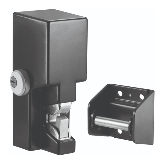
• Self-aligning receiver (up to +/- 1/2" horizontally or vertically) helps compensate for gate misalignment and sag • Tamper proof cast housing • Latch status monitor switch (SPDT) • ½”-14 NPSM inside pipe thread • Surface Mount • Black finish Product Components Upon unpacking this product, an inventory should be made to ensure that all the required components and hardware have been... -
Page 5: Installing The Gl1 Electromechanical Gate Lock
Installing the GL1 Electromechanical Gate Lock Installation Concerns CAUTION: It is vital that all welding be completed prior to making any electrical connections to the mounted GL1. Welding in or around an electrically-connected lock assembly can cause damage to the electronic components. - Page 6 assembly should be installed in a location that will not hinder or create a potential safety hazard to authorized personnel routinely accessing the protected area. Because of the diversity in gate construction and installation configurations, optimum mounting platforms may be achieved by welding adequate size metal plates, channels or tubing to the fence frame and the gate.
- Page 7 Figure 3. Installation Spacing Dimensions Figure 4. Chassis Welding 7 500-22090, Rev A...
-
Page 8: Perform The Cylinder Lock/Cover Hole Plug Installation
Perform the Cylinder Lock/Cover Hole Plug Installation NOTE 1: The GL1 provides for the additional function of an optional key- operated cylinder lock. The cylinder lock can be installed to either side of the lock cover, because the GL-1 lock latching mechanism features an actuator lever that will engage the cylinder lock from either side. - Page 9 Figure 5. Cylinder Lock Installation c. SLIP the spacer over the cylinder lock and INSERT the cylinder lock into the applicable side hole on the lock cover. d. SLIP the lock mounting nut over the cylinder lock inside the cover and THREAD the nut onto the lock body by hand. e.
-
Page 10: Mount The Gl1 And Connect The Electrical
Figure 6. Cover Hole Plug and Retaining Nut Mount the GL1 and Connect the Electrical NOTE: The FMK-SL (Sliding Gate) and the FMK-SW (Swing Gate) mounting bracket kits are recommended for installing the GL1. 1. IF not using one of the recommended mounting bracket kits, THEN USE the included template to locate and install mounting hardware. - Page 11 3. ROUTE all electrical wiring through either the provided wire conduit coupling in the bottom of the lock chassis or through the ½” [12.7 mm] hole in the rear of the lock mounting chassis (see Figure 7, “Wire Routing”). 4. FEED wires through the hole in the side of the lock chassis opposite to the cylinder lock, if installed.
- Page 12 Figure 8. PC Board Terminal Block Figure 9. System Connections 7. PERFORM a functional test of the GL1. 12 500-22090, Rev A...
-
Page 13: Complete The Gl1 Installation
Complete the GL1 Installation CAUTION: Lock cover must be installed straight on to avoid possible damage to the PC Board. 1. INSTALL the lock cover over the lock mounting chassis by placing the cover straight on and then sliding to engage. 2. -
Page 14: Troubleshooting
Troubleshooting PROBLEM: The lock does not latch. ▪ CHECK lock-to-strike engagement distance—strike may be mounted too far away from the lock. ▪ CHECK wire routing to ensure wiring does not impede the function of the lock mechanism manual override/actuator lever, or behind lock catch. -
Page 15: Magnacare Lifetime Replacement Warranty
PROBLEM: Cover does not fit on the lock. ▪ CHECK welding—If the lock chassis was welded to the mounting surface; verify that there are no welds that extend beyond the edge of the chassis back plate. ▪ CHECK wire routing to ensure that the placement of the wires is not inhibiting the proper fit of the cover to the lock chassis. - Page 16 Phoenix, AZ 85044 Tel: 1-800-624-5625 Mon-Fri: 6:00am - 4:00pm PDT Fax: 1-800-232-7329 s e c u r i t r o n . c o m 16 500-22090, Rev A © 2014, Hanchett Entry Systems, I nc., an ASSA ABLOY Group Company.
Need help?
Do you have a question about the Securitron GL1 and is the answer not in the manual?
Questions and answers