Table of Contents
Advertisement
Quick Links
TLE4972 Current sensor programmer
User guide
About this document
This document describes feature set, hardware and software layers of the Infineon Current Sensor Programmer.
Scope and purpose
The purpose of this document is to guide the user in the programming, calibration and general evaluation of
compatible TLE4972 sensing boards using the Infineon Current Sensor Programmer.
Intended audience
This document is written for TLE4972 users who are dealing with the implementation of the product in the
system.
Evaluation Board
Infineon's magnetic current sensor evaluation kit consists of the Current Sensor Programmer board, USB
cable and evaluation board connection cable. The programmer GUI along with Current Sensor Programmer
board can be used to evaluate, program and calibrate Infineon's set of evaluation boards or a customized PCB
setup. The programmer board is to be used by the customer solely for the purpose of evaluation and testing. It
is not a commercialized product and shall not be used for series production. The programmer board is thus not
intended to meet any industrial specifications and the recommended operating ambient temperature is 80°C.
The following key aspects are discussed in this document:
•
Programmer board and evaluation board order information;
•
Programmer board and GUI description;
•
Programmer board ELV and SELV isolation scheme;
•
GUI installation procedure;
•
Typical application setup with and without Infineon evaluation boards;
•
GUI operation with and without Infineon evaluation boards;
•
Easy programming of current sensor parameters such as operating mode, sensitivity, overcurrent threshold
and deglitch filtering time;
•
Internal signals readout (e.g. internal temperature);
•
Crosstalk compensation procedure;
•
Calibration procedure.
Table 1
Programmer and evaluation boards ordering codes
Device name
CUR SENSOR PROGRAMMER
TLE4972 EVAL STD PCB
TLE4972 EVAL INLAY
(table continues...)
User guide
Please read the sections "Important notice" and "Warnings" at the end of this document
www.infineon.com
SP number
SP004441438
SP005632136
SP005632138
Device information
Current Sensor Programmer for
TLE4972
TLE4972 TDSO, multi-layer FR4
board, 45° S-bend
TLE4972 TDSO, FR4 board with
copper inlay, 45° S-bend
Rev. 1.00
2022-04-05
Advertisement
Table of Contents

Related Manuals for Infineon TLE4972


Summary of Contents for Infineon TLE4972
- Page 1 The purpose of this document is to guide the user in the programming, calibration and general evaluation of compatible TLE4972 sensing boards using the Infineon Current Sensor Programmer. Intended audience This document is written for TLE4972 users who are dealing with the implementation of the product in the system. Evaluation Board Infineon’s magnetic current sensor evaluation kit consists of the Current Sensor Programmer board, USB...
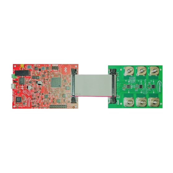
- Page 2 TLE4972 VSON, Busbar, 45° S-bend Figure 1 TLE4972 Current Sensor Programmer The Current Sensor Programmer board connection with a 3-phase TLE4972 evaluation board is shown in the figure below. The communication between the current sensor and programmer board is done through an interface cable.
-
Page 3: Table Of Contents
TLE4972 Current sensor programmer User guide Table of contents Table of contents Table of contents ............... 3 Important notice . - Page 4 TLE4972 Current sensor programmer User guide Table of contents FTDI drivers installation ..............32 Abbreviations and definitions .
-
Page 5: Important Notice
Boards provided by Infineon Technologies. The design of the Evaluation Boards and Reference Boards has been tested by Infineon Technologies only as described in this document. The design is not qualified in terms of safety requirements, manufacturing and operation over the entire operating temperature range or lifetime. -
Page 6: Safety Precautions
TLE4972 Current sensor programmer User guide 2 Safety precautions Safety precautions Note: Please note the following warnings regarding the hazards associated with development systems. Figure 3 Safety Precautions • Warning: Remove or disconnect power from the drive before you disconnect or reconnect wires, or perform maintenance work. -
Page 7: The Board At A Glance
3 The board at a glance The board at a glance Delivery content 3.1.1 Software overview The required software can be acquired from the respective Infineon sales person. The software package contains: • A Graphical User Interface (GUI); • FTD chipset USB driver, which is necessary to establish the USB connection. It enables USB 2.0 and USB 3.0 protocol capabilities. - Page 8 TLE4972 Current sensor programmer User guide 3 The board at a glance Figure 4 Current Sensor Programmer board features User guide Rev. 1.00 2022-04-05...
-
Page 9: Block Diagram
TLE4972 Current sensor programmer User guide 3 The board at a glance Block diagram The figure below shows the block diagram of the programmer board. To provide the required safety isolation level, the controller and interface circuits are isolated. The Micro-USB connector is isolated from the microcontroller through the reinforced insulation of the DC-DC converter. -
Page 10: System And Functional Description
4.1.1 Initial setup The figure below shows an example about how to connect the TLE4972 evaluation boards with the programmer board via USB connector to a PC or laptop in case of general purpose drive application. Here, the green color board shown in the figure below could be either of the following boards: •... - Page 11 4 System and functional description Figure 7 Connection with programmer board If an Infineon evaluation board is connected as DUT board, the "Continuous readout" window will appear (Chapter 4.2.4.1) and the led D2 on the programmer board will start blinking. The software GUI will automatically configure itself using configuration data stored on the Infineon evaluation board external EEPROM.
-
Page 12: Initial Setup With Generic Dut Board
4.2.1. The following window will pop- up if the user did not connect an Infineon evaluation board but a custom DUT board, without a properly programmed external EEPROM on it. The user has to enter the expected sensitivity in [mV/A] and confirm it by selecting the "Set"... -
Page 13: Sensor Not Recognized
TLE4972 Current sensor programmer User guide 4 System and functional description 4.1.3 Sensor not recognized If the "Not supported" indication appears in the "Design Step" text box, the sensors on the DUT board have not been recognized. This might be due to malfunctioning sensors, or to interface problems such as soldering issues, bad cabling or wrong connection scheme. -
Page 14: Description Of The Functional Blocks
TLE4972 Current sensor programmer User guide 4 System and functional description Description of the functional blocks 4.2.1 DUT board connector The DUT board connector is used to establish the connection between the programmer and the DUT board. The figure and table below show the DUT board connector pinout. - Page 15 TLE4972 Current sensor programmer User guide 4 System and functional description Table 2 (continued) DUT board connector pinout OCD1_3 Over Current Detection channel 1 of sensor 3 (open drain) VREF3 Reference voltage of sensor 3 OCD2_3 Over Current Detection channel 2 of...
-
Page 16: Measurement Header
TLE4972 Current sensor programmer User guide 4 System and functional description 4.2.2 Measurement header The figure and table below show the pinout of the measurement header. It can be used to connect measurement instrumentation directly to the programmer board. AOUT1... -
Page 17: Optional External Power Supply Connection
Optional external power supply connection The programmer board typically draws about 350 mA when connected to the TLE4972 evaluation boards. This current can be delivered via the USB port of a PC, which is usually specified to deliver up to 500 mA. A reverse current protection diode ensures safe operation and protects the USB port of the Laptop/PC in case power is provided through the measurement header at the same time. -
Page 18: Mode Selection
TLE4972 Current sensor programmer User guide 4 System and functional description 4.2.4 Mode selection 4.2.4.1 Continuous readout The figure below shows the GUI software appearance when the programmer board is successfully connected to the DUT board. The Continuous readout mode is selected by default. -
Page 19: Double Code Word Calibration
TLE4972 Current sensor programmer User guide 4 System and functional description Basic configuration Figure 14 Basic configuration mode This mode is based on 5 visual items: Current Rail Transfer Factor: this is the transfer factor in [µT/A] associated with the sensing structure. The value must be known from simulations or measured on the final system. - Page 20 TLE4972 Current sensor programmer User guide 4 System and functional description Double Code Word Calibration Step by step instructions Figure 15 Double Code Word Calibration mode This mode is based on 8 visual items: Select sensor: this dropdown menu has to be used to select which sensor has to be calibrated;...
- Page 21 TLE4972 Current sensor programmer User guide 4 System and functional description Input target sensitivity and test current; Supply the test current for the selected sensor and click on the button "Vout@Itest"; Stop the current supply when new values are generated in the text fields on the right of the button;...
-
Page 22: Options Drop Down Menu
EXT EEPROM This menu item is used to fetch the information from the external EEPROM of the Infineon's evaluation boards. The figure below shows the dialog box that will pop up if user selects the menu item "EXT EEPROM" under the "Options"... -
Page 23: Temperature Readout
Further information are available on the User manual [2] and by clicking on the "?" button; • Unique ID: unique identifier of the evaluation board. Useful for direct support by Infineon; • TLI4971/TLE4972 Standard buttons: to reset the external EEPROM content to default values;... -
Page 24: Register Readout
TLE4972 Current sensor programmer User guide 4 System and functional description 4.2.5.3 Register Readout This menu item opens the Register Readout window. This window allows the user to observe the change of internal registers in real time, for testing purposes. If the registers readout is executing then analog output and OCDs output are not reliable, since the sensors are put into test mode. -
Page 25: Memory Drop Down Menu
By clicking on the Burn EEPROM button, the internal EEPROM of the sensors is effectively programmed. In case an Infineon evaluation board is connected, the software will ask the user whether to update the external EEPROM of the evaluation board to fit to the new programmed sensor settings, as shown in the figure below. -
Page 26: Eeprom Map
TLE4972 Current sensor programmer User guide 4 System and functional description 4.2.6.2 EEPROM Map This menu item opens the EEPROM Mapping window, allowing the user to store, load and modify the internal EEPROM of the sensors on the DUT board. Before modifying the internal EEPROM content it is suggested to store the original internal EEPROM content of the sensor;... - Page 27 Chapter 4.2.4.3 explained in details in the User manual [2]. The calibration parameters should not be changed manually by the user unless directly indicated by Infineon. It is strongly recommended to store the original internal EEPROM content as explained in Chapter 4.2.6.2...
-
Page 28: Tools Drop Down Menu
TLE4972 Current sensor programmer User guide 4 System and functional description 4.2.7 Tools drop down menu 4.2.7.1 OCD Calculation Tool This menu item opens the OCD Calculation Tool window. It allows to setup the OCD thresholds for OCD1 and OCD2 pins, if the Current Rail Transfer Factor is known. The latter can be estimated using the software... -
Page 29: Calibrate Toolbox
(more than 10) and to consider the average value. 4.2.7.3 Calibrate Toolbox This menu item starts the Current Sensor Programmer board sensor inputs calibration. This calibration procedure is not needed unless directly indicated by Infineon. User guide Rev. 1.00 2022-04-05... -
Page 30: References And Appendices
TLE4972 Current sensor programmer User guide 5 References and appendices References and appendices GUI software installation The following initial setup window will display when the user starts the installation by double clicking on the "Current Sensor Evalkit Vx.x.x.exe". Click "Next" to continue with the installation. - Page 31 TLE4972 Current sensor programmer User guide 5 References and appendices Then the installer will prompt for the installation folder. Accept the default one or use another directory by selecting the "Browse" button as shown in Orange color box. Click "Next" to continue with the installation.
-
Page 32: Ftdi Drivers Installation
TLE4972 Current sensor programmer User guide 5 References and appendices Figure 29 EvalKit Installer – Installation Completed FTDI drivers installation After software installation, the FTDI CDM Drivers need to be installed, if not already installed. When the user runs the "Current Sensor Evalkit Vx.x.x.exe" file a parallel window to the installer window is automatically opened at the end of the installation procedure. - Page 33 TLE4972 Current sensor programmer User guide 5 References and appendices Figure 31 FTDI CDM Drivers – Installation Wizard Read through the license agreement carefully and continue the installation by accepting it (see orange color box). If the license agreement is not accepted the installation will be aborted. Click "Next" to continue with the installation.
- Page 34 TLE4972 Current sensor programmer User guide 5 References and appendices Figure 33 FTDI CDM Drivers – End of Installation To start the GUI software, go to the Windows Start button and type "Current sensor evalkit" in the search box, then select it.
-
Page 35: Abbreviations And Definitions
TLE4972 Current sensor programmer User guide 5 References and appendices Abbreviations and definitions Notation Description Alternating Current European Conformity Direct Current Electro-Magnetic Compatibility EEPROM Electrically Erasable Programmable Read-Only Memory Electro-Static Discharge Finite Element Method Graphical User Interface Over Current Detection... -
Page 36: References
TLE4972 Current sensor programmer User guide 5 References and appendices References [1] Infineon-TLE4972-AE35S5-DS-vxx_xx-EN.pdf; Infineon-TLE4972-AE35D5-DS-vxx_xx-EN.pdf [2] Infineon-TLE4972-User_manual-vxx_xx-EN User guide Rev. 1.00 2022-04-05... -
Page 37: Revision History
TLE4972 Current sensor programmer User guide 6 Revision history Revision history Document revision Date of release Description of changes 01.00 05.04.2022 Initial release. User guide Rev. 1.00 2022-04-05... -
Page 38: Disclaimer
Infineon Technologies, All Rights Reserved. information given herein in the real application. Infineon Technologies’ products may not be used in Infineon Technologies hereby disclaims any and all any applications where a failure of the product or warranties and liabilities of any kind (including without...
Need help?
Do you have a question about the TLE4972 and is the answer not in the manual?
Questions and answers