
Subscribe to Our Youtube Channel
Related Manuals for Still CX


Summary of Contents for Still CX
- Page 1 Original instructions Low level order picker CX CX-D CX-H 1063 1069 50108043405 EN - 02-04/2014...
-
Page 3: Table Of Contents
Table of contents Foreword Your industrial truck ........... 2 General . - Page 4 CX-H version ........
- Page 5 Table of contents Connecting the battery plug (charging station) ....... 58 Commissioning .
- Page 6 Table of contents Cold store use ............83 Designation .
- Page 7 Table of contents Maintenance safety instructions ......... 112 Safety measures for maintenance and repair .
- Page 8 Table of contents Technical characteristics Dimensions ............140 Datasheet (VDI) .
-
Page 9: Foreword
Foreword... -
Page 10: Your Industrial Truck
Foreword Your industrial truck Your industrial truck General The truck described in these operating instruc- tions corresponds to the applicable standards and safety regulations. If the truck is to be operated on public roads, it must conform to the existing national regula- tions for the country in which it is being used. -
Page 11: Ec Declaration Of Conformity In Accordance With Machinery Directive
Foreword Your industrial truck EC declaration of conformity in accordance with Machinery Directive Declaration STILL GmbH Berzeliusstraße 10 D-22113 Hamburg Germany We declare that the according to these operating instructions Industrial truck according to these operating instructions Model conforms to the latest version of the Machinery Directive 2006/42/EC. -
Page 12: Information About Documentation
Foreword Information about documentation Information about documentation Documentation scope • Operating instructions • Operating instructions for attachment parts (special equipment) • Spare parts list • VDMA rules for the proper use of industrial trucks These operating instructions describe all mea- sures necessary for the safe operation and proper maintenance of the truck in all possible variants at the time of printing. - Page 13 Foreword Information about documentation Thank you for reading and complying with these operating instructions. If you have any questions or suggestions for improvements, or if you have found any faults, please contact your service centre. 50108043405 [EN]...
-
Page 14: Date Of Edition And Latest Update Of This Manual
Foreword Information about documentation Date of edition and latest update of this manual The publication date of these operating instructions is printed on the cover sheet. The manufacturer makes continuous efforts to improve its industrial trucks, and therefore reserves the right to implement changes and to accept no claims concerning the information provided in this manual. -
Page 15: Explanation Of Symbols Used
Foreword Information about documentation Explanation of symbols used DANGER Compulsory procedure that must be followed to avoid danger to life or physical harm. WARNING Compulsory procedure that must followed to avoid injury. CAUTION Compulsory procedure that must be followed to avoid material damage and/or destruction. -
Page 16: Definition Of Directions
Foreword Information about documentation Definition of directions The references forward (1), backward (3), right (2) and left (4) when describing location are made relative to the operator’s station. The load is at the rear. 1044_001-014 Sample graphics This documentation explains the (usually sequential) sequence of certain functions or operations. -
Page 17: Environmental Considerations
Foreword Environmental considerations Environmental considerations Packaging During delivery of the truck, certain parts are packaged to provide protection during transport. This packaging must be removed completely prior to initial start-up. ENVIRONMENT NOTE The packaging material must be disposed of properly after delivery of the truck. Disposal of components and batteries The truck is composed of different materials. - Page 18 Foreword Environmental considerations 50108043405 [EN]...
-
Page 19: Introduction
Introduction... -
Page 20: Technical Description
Introduction Technical description Technical description Drive The CX 20 and CX-D 20 are fitted with a 3 kW traction motor driving the drive wheel via a transmission gear: • Asynchronous travel motor, 3 kW • Starting and accelerating without jerking •... - Page 21 Introduction Technical description Driving All functions and controls—which are both sturdy and ergonomic—are centralised in the cockpit, enabling the operator to direct the drive wheel and steering wheel effortlessly. The following controls can be activated from the cockpit: "Start", "Tortoise" and "Hare" but- tons, number buttons, "Confirmation"...
-
Page 22: Use Of The Truck
Introduction Use of the truck Features of the CX-D 20 • Initial lift and main lift of 1580 mm. Allows two pallets to be lifted at the same time. • Max. load of 2000 kg on the initial lift or two times 1000 kg on the initial lift AND main lift. -
Page 23: Impermissible Use
Introduction Use of the truck must be obtained beforehand to prevent any potential dangers. The maximum load that can be lifted is speci- fied on the load capacity plate (load diagram). Do not exceed the maximum load capacity. Impermissible use The user, and not the manufacturer, is liable for any hazards caused by improper use. -
Page 24: Residual Risks
Introduction Residual risks Residual risks Residual dangers, residual risks Despite careful working and compliance with standards and regulations, the occurrence of other risks when using the truck cannot be entirely excluded. The truck and all other system components comply with current safety requirements. Nevertheless, even when the truck is used for its proper purpose and all instructions are followed, some residual risk cannot be... -
Page 25: Special Risks Associated With Using The Truck And Attachments
Introduction Residual risks The manufacturer is not held responsible for accidents involving the truck caused by the failure of the operating company to comply with these regulations either intentionally or carelessly. Stability The stability of the truck has been tested to the latest technological standards and is guaranteed if the truck is used properly and according to its intended purpose. -
Page 26: Overview Of Hazards And Countermeasures
Introduction Residual risks Overview of hazards and counter- measures NOTE This table is intended to help evaluate the hazards in your facility and applies to all drive types. It does not claim to be complete. NOTE Observe the national regulations for your country! Hazard Measure... - Page 27 Introduction Residual risks Hazard Measure Check note Notes √ actioned - not applicable Impermissible usage Issuing of operating BetrSichVO (improper usage) instructions (Workplace Safety Ordinance) and ArbSchG (Health and Safety at Work Act) Written notice of BetrSichVO instruction to driver (Workplace Safety Ordinance) and ArbSchG (Health and...
-
Page 28: Hazards To Employees
Introduction Residual risks Hazard Measure Check note Notes √ actioned - not applicable With driverless transport systems Roadway quality Clean/clear driveways BetrSichVO inadequate (Workplace Safety Ordinance) Load carrier Reattach load to pallet BetrSichVO incorrect/slipped (Workplace Safety Ordinance) Drive behaviour Employee training BetrSichVO unpredictable (Workplace Safety... - Page 29 Introduction Residual risks The results must be documented (§ 6 Arb- SchG). In the case of truck deployment involv- ing similar hazard situations it is permitted to summarise the results. This overview (see ⇒ Chapter "Overview of hazards and coun- termeasures", P.
- Page 30 Introduction Residual risks 50108043405 [EN]...
-
Page 31: Safety
Safety... -
Page 32: Definition Of Terms Used For Responsible Persons
Safety Definition of terms used for responsible persons Definition of terms used for responsible persons Operating company The operating company is the natural or legal person or group who operates the truck or on whose authority the truck is used. The operating company must ensure that the truck is only used for its proper purpose and in compliance with the safety regulations set out... -
Page 33: Expert
Safety Definition of terms used for responsible persons truck to be tested and the risk being as- sessed. Expert An expert is considered to be someone whose technical training and experience have en- abled them to develop appropriate knowledge of industrial trucks and who is sufficiently fa- miliar with the applicable national health and safety regulations, directives and generally recognised technical conventions (standards,... - Page 34 Safety Definition of terms used for responsible persons and safety gloves) suited to the operating con- ditions, the job and the load to be lifted. The driver must wear safety footwear for driving and braking in complete safety. The drive must be familiar with the operating instructions, which must remain accessible at all times.
-
Page 35: Basic Principles For Safe Operation
STILL. CAUTION Installation and/or use of such products may there- fore have a negative impact on the design features of the truck and thus impair active and/or passive driving safety. -
Page 36: Medical Equipment
Safety Basic principles for safe operation You should therefore contact the manufac- turer before carrying out any modification. No modification that may affect stability is permit- ted without the manufacturer’s authorisation. Any constructional modification or transfor- mation of your truck is forbidden without prior written permission from the manufacturer. -
Page 37: Safety Tests
Safety tests Regular safety inspection of the truck Safety inspection based on time and extraordinary incidents STILL GmbH Hamburg The operating company must ensure that the truck is checked by a specialist at least once a Regelmäßige Prüfung year or after particular incidents. - Page 38 Safety Safety tests Measuring battery insulation resistance NOTE Nominal battery voltage < test voltage < 500V. – Measure insulation resistance using a suitable meter. The insulation resistance is sufficient when it has a nominal value of at least 1000 Ohms/V against the chassis.
-
Page 39: Safety Regulations For Handling Consumables
Safety Safety regulations for handling consumables Safety regulations for handling consumables Permissible consumables DANGER Failure to observe the safety regulations relating to consumables may result in a risk of injury, death or damage to the environment. – Observe the safety regulations when handling such materials. -
Page 40: Hydraulic Fluid
Safety Safety regulations for handling consumables WARNING Prolonged intensive contact with the skin can result in dryness and irritate the skin! – Avoid contact and consumption. – Wear protective gloves. – After any contact, wash the skin with soap and water, and then apply a skin care product. -
Page 41: Battery Acid
Safety Safety regulations for handling consumables WARNING These fluids are pressurised during operation of the truck and are hazardous to your health. – Do not allow the fluids to come into contact with the skin. – Avoid inhaling spray. – Penetration of pressurised fluids into the skin is particularly dangerous if these fluids escape at high pressure due to leaks in... -
Page 42: Disposal Of Consumables
Safety Safety regulations for handling consumables WARNING Battery acid contains dissolved sulphuric acid. This is corrosive. – When working with battery acid, always wear a protection suit and eye protection. – When working with battery acid, never wear a watch or any jewellery. -
Page 43: Emissions
Safety Safety regulations for handling consumables Emissions Noise emissions The noise specifications in the technical data were determined according to CEN standard "Noise measurement of industrial trucks, sound level at the workplace and sound power level" (in preparation). The sound power level at the driver’s station is 65 dB(A). - Page 44 Safety Safety regulations for handling consumables avoided through sufficient ventilation and by avoiding naked flames. Follow the safety precautions for handling the traction battery. 50108043405 [EN]...
-
Page 45: Safety Devices
Safety Safety devices Safety devices Damage, defects and misuse of safety devices The driver must report any damage or other defects to the truck or attachment immediately to the supervisory personnel. Trucks and attachments that are not functional or safe may not be used until they have been properly repaired. - Page 46 Safety Battery connection cables 50108043405 [EN]...
-
Page 47: Overview
Overview... -
Page 48: General View
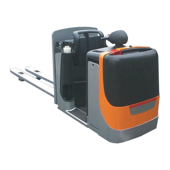
Overview General view General view 1044_000-005 Battery connector Battery Tiller Brake Pedestrian mode traction button (option) Drive motor Backrest Gearbox Pedestrian mode traction button (option) Traction wheel Steering motor Load wheel Forks Stabiliser Lift cylinder Hydraulic oil tank AC controller Pump motor Platform Fuse mount... -
Page 49: Controls And Display Elements
Overview Controls and display elements Controls and display elements View of the control elements 1044_000-008 Cubby hole Cubby hole Battery compartment lock Pedestrian mode traction button (option) Tiller Cushion Battery plug Pedestrian mode traction button (option) Presence area Cubby hole 50108043405 [EN]... -
Page 50: Cx 20 Cockpit
Overview Controls and display elements CX 20 cockpit 6 7 8 1044_000-006 Lower button Numbers button Lift button button Hare Horn button Horn button button Lift button Tortoise (scrolling) button Lower button PRG ↑ Numbers button Handle Travel control Display... -
Page 51: Version With Movable Step Plate (Optional)
Overview Controls and display elements Version with movable step plate (optional) • (1) Step plate lowering pedal • (2) Step plate raising pedal • (3) Emergency stop button • (4) Handholds • (5) Button for slow movement of truck towards the motor side (where present) •... -
Page 52: Cx-H Version
Overview Controls and display elements CX-H version 800 Kg 600 mm 800 Kg 1800 mm 800 Kg 800 Kg 2259 The capacity plate (1) indicates truck load capacity in kg according to the centre-of- gravity distance and lift height. If two loads are transported at the same time, arrange the loads as shown on the plate (1). -
Page 53: Marking Positions
Overview Marking positions Marking positions Location of plates and labels Warning label Manufacturer’s logo Manufacturer’s logo and product code Customer’s logo (option) Manufacturer’s plate Warning label Hook symbol "Do not sling" symbol Warning label Emergency stop label "Do not mount" label Serial number label (bar code on the chas- Hook symbol sis) -
Page 54: Labels
Overview Marking positions Labels Operating instructions Do not lift a load with the initial lift in the upper Slinging - See the operating instructions position UVV support (Germany only) Do not step under a raised load UVV plate (Germany only) Do not climb Company plate Do not stand on the forks... - Page 55 Overview Marking positions On-board charger label Automatic mode selection indicator (EXU-H Mains connector (on-board charger) autolift only) "Plugs" label Manual or automatic mode selection Hydraulic filler (EXU-H autolift only) Maximum pressure (example) Automatic lifting/lowering mode selection Platform pressure diagram (example) Arrows Operating mode indication label Cold store...
-
Page 56: Chassis Frame Labelling
Overview Marking positions Chassis frame labelling The truck’s serial number is marked on the chassis frame (1). OM2271 Data plate NOTE Please indicate the serial no. for all technical enquiries. Model Manufacturer Serial no. Year of manufacture Unladen weight (without battery) in kg Maximum battery weight Minimum battery weight Additional weight (ballast) in kg... -
Page 57: Options And Variants
Overview Options and variants Options and variants Overview of options and models CX-D 20 20/CX-H Optional Dimensions Lowering locking during Optional Optional travel 115 mm – 520 mm Standard Optional Standard Exterior fork width b5 560 mm Optional – 670 mm Boot 97 for 24 V / 345–465 Ah battery with... - Page 58 Overview Options and variants CX-D 20 20/CX-H Optional Dimensions Fork end pieces With input/output sliding shoes Optional – Type with rubber buffer, 165 mm high, fitted Optional Optional on the drive area Bumpers Type with a metal guard, 545 mm high, fitted...
-
Page 59: Overview Of Accessories
Standard Standard Optional Optional SBE 320 red Electrically and mechanically set up on the front part for scanner and 8.4" or 12.1" STILL terminal including 24 V/5 A electrical power Optional Optional supply, interface cable with a 3-pole socket MMS Preparation and a standard VESA75 bracket with holes. -
Page 60: Battery Electrolyte Level Indicator Led (Optional)
Overview Options and variants released by pulling the key out with the battery cover open, thus leaving the cover unlocked. The instructions for the use of the key for opening and closing the battery cover do not apply then. Battery electrolyte level indicator LED (optional) There are two versions of the LED: •... -
Page 61: Load Back Rest With Vertical Pallet Hook (Optional)
Overview Options and variants Load back rest with vertical pallet hook (optional) Hand protective guard (L): • Do not remove the guard • Before using the truck, check that there is a protective guard and that this guard is intact The system allows you to transport empty pallets in a vertical position in the following two ways:... - Page 62 Overview Options and variants • Repeat the preceding steps for the other clamp (E) • Push the bar (G) downwards (A) to raise clamps (D) and (E) • Position the pallet in the position defined (2) and clamp it between the clamps (E), pulling the bar (G) towards (B) CAUTION Risk of crushing hands and feet...
-
Page 63: Operation
Operation... -
Page 64: Intended Use Of The Trucks
Operation Intended use of the trucks Intended use of the trucks CAUTION This machine is designed for order picking (col- lecting and gathering together items stored in the warehouse before dispatch), horizontal transport tasks and entering and removing pallets to and from stock. - Page 65 Operation Checks and actions prior to use • Visually check that the various truck com- ponents are in good condition • Check that the fork arms are in good condition • Check that all of the commands work correctly: buttons, throttles etc. •...
-
Page 66: Connecting The Battery Plug (Charging Station)
Operation Commissioning DANGER DO NOT use the truck, but call the technical service department, if you notice any malfunctions or if you have any doubts about its correct operation. Connecting the battery plug (charg- ing station) – Disconnect the battery socket (1) from the charging station and insert into the plug on the truck. -
Page 67: Entering The Driver Code
Operation Commissioning Entering the driver code – Press the (ON) button (6). The message (8) will appear in the display (4) and CodE disappear after approx. 1 s. This is the prompt to enter your valid 4-digit driver code. Enter the code in the same way as entering characters on a mobile phone. -
Page 68: Starting With Fleetmanager (Optional)
Operation Commissioning – The number is deleted, the flashing line cursor (9) appears again. The code number can be re-entered. – After the 4th number is entered, confirm the input by depressing the button (5). PRG ↲ The manufacturer’s name appears briefly in the display. -
Page 69: Hour Meter
Operation Commissioning Hour meter The display changes approx. 4-5 s after powerup to show the operating hours (1) and the hour-glass symbol (2). These are the total number of hours since the commissioning of the pallet truck. The meter always runs when the pallet truck is driven or a load is raised. -
Page 70: Display Of Time To Next Servicing
Operation Commissioning Display of time to next servicing – Press the (scrolling) button (4) to PRG ↑ display the time remaining until the next scheduled servicing. The time is shown in hours (6) and with the symbol of a spanner (5). -
Page 71: Checking The Presence Area And Brake
Operation Commissioning Checking the presence area and brake – Drive the truck. – Leave the presence area (8). The truck will brake to a stop. 1044_001-009 Checking the emergency brake – Drive the truck slowly using the traction control (4). –... -
Page 72: Driving
Operation Driving Driving Driving safety instructions Driving conduct The driver must follow the public rules of the road when driving in company traffic. The speed must be appropriate to the local conditions. For example, the driver must drive slowly around corners, in tight passageways, when driving through swing-doors, at blind spots, or on uneven surfaces. -
Page 73: Before Driving
Operation Driving Before driving Dimensions of roadways and aisles The dimensions and aisle widths contained in section description apply under established conditions to ensure safe driving. Check, when necessary, if a wider aisle is required when the load dimensions differ. The required aisle widths (Ast) depend on the dimensions of the load and may be calculated following the formula: Ast = Wa - X + Length of... -
Page 74: Emergency Stop Procedure
Operation Driving Rules for roadways and work area Only the roads released for traffic by the operator or his representative may be driven on. The roadways must be free of obstacles. The load may only be stacked and stored at the appropriate places. -
Page 75: Persons In The Danger Area
Operation Driving WARNING Danger of personal injury Do not step on the forks. WARNING Persons can be injured in the danger zone of the truck. No person, except the driver in his normal operating position, may stand in the danger zone of the truck. If persons refuse to leave the danger zone despite warnings, stop working with the truck immediately and secure it against use by unauthorized persons. -
Page 76: Driving In Rider Mode
Operation Driving Driving in rider mode – Step on the platform with both feet and step on the presence area (1). NOTE The pallet truck is turned on. WARNING There should be no objects lying on the floor of the driver’s platform, whose weight could activate the dead man’s switch under the mat. -
Page 77: Selecting The Driving Mode
Operation Driving Driving forward – Depress the top part of the throttle (2) or (3) with the thumb. – Truck speed is increased by depressing the travel control further. – When the travel control is released, the truck is braked electrically. Reversing –... -
Page 78: Driving, Pedestrian Operation With Tiller, Slow Approach With Drive Switch
Operation Driving Driving, pedestrian operation with tiller, slow approach with drive switch – From the side, grip the handle (1) or (4) on the tiller. NOTE The lift truck is switched on. CAUTION Take care when operating, especially if the user is not familiar with using this function. - Page 79 Operation Driving Backwards driving – Press the lower part of the drive switch with your thumb. – The speed of the fork lift truck increases as you push the traction switch further, up to a limit of 2,5 km/h. – When the traction switch is released, the fork lift truck brakes electrically.
-
Page 80: Driving, Pedestrian Operation With Push Button
Operation Driving DANGER Risk of crushing feet. Do not use this function for turning. This function is designed to maintain a straight line. Proceed from the cockpit with very slight move- ments. NOTE The lift truck must be switched on. If the push button (4) or (5) are pushed in for quite a long time, a safety circuit immobilises the truck. -
Page 81: Steering
Operation Driving Steering The truck is steered by turning the tiller in range (1). The turning radius (Wa) depends on the fork length and the battery (refer to the table). Turning radius (Wa) values for the calculation of aisle widths (all values in mm) Fork lengths 450 Ah 600 Ah... - Page 82 Operation Driving – Leave the presence area (3). 1044_501-010 – Release the pedestrian mode traction button (4) or (5). Average braking – Operate travel control (1) or (2) in the opposite direction. 1044_501-007 50108043405 [EN]...
-
Page 83: Emergency Stop Brake
Operation Driving Emergency stop brake CAUTION This brake may only be used in an emergency. – Depress the emergency brake switch (6). The truck is braked to a fast stop. – appears in the display (7). SToP NOTE After the disappearance of StoP in the display, press the (ON) button (8) to restart work. -
Page 84: Lifting
Operation Lifting Lifting Lifting device controls WARNING Risk of injury! Always follow the safety rules exactly ⇒ Chap- ter "Load handling safety rules", P. 5-77. Do not put your hand or step into moving parts (eg mast, sideshift, implements, load lifting device, etc.). -
Page 85: Handling Loads
Operation Handling loads Handling loads Load handling safety rules WARNING DANGER Closely observe the following instructions before picking up loads. Never touch or stand on moving parts of the truck (e.g. lifting device, pushing devices, work installations or devices for picking up loads). -
Page 86: Picking Up A Loading Unit
Operation Handling loads Picking up a loading unit In order to guarantee load stability, ensure that the load is balanced and centred on the fork arms and that the fork arms have been sufficiently slid underneath the load. The load should not excessively extend over the fork arms , nor should the fork arms excessively protrude out from the load. -
Page 87: Palletising A Load
Operation Handling loads the area within the range of falling loads or a descending working device. WARNING Danger of personal injury Do not step on the forks. WARNING Persons can be injured in the danger zone of the truck. No person, except the driver in his normal operating position, may stand in the danger zone of the truck. -
Page 88: Transporting Pallets Or Other Containers
Operation Handling loads Transporting pallets or other contain- Under normal circumstances, unit loads (e.g. pallets) should be transported individually. Simultaneous transport of more than one unit load is only permitted • on instruction of the supervisor and • if the technical requirements are met. The driver must satisfy himself that the load is in proper condition. -
Page 89: Driving On Gradients
Operation Handling loads Driving on gradients When driving on gradients, the load must be positioned on the uphill side. It is only permitted to drive on gradients which are identified as suitable for traffic and which can be safely negotiated. The driver must satisfy himself that the ground is clean and provides good grip. -
Page 90: Entering Lifts
Operation Handling loads Entering lifts The driver may only enter lifts with a sufficient load capacity and with the permission of the operator. Inside the lift, the truck must be secured so that no part of it will come into contact with the wall of the lift shaft. -
Page 91: Cold Store Use
Operation Cold store use Cold store use Designation Your truck is fitted with special equipment for use in cold stores. It can be used for two operating ranges and carries a cold store label. The cold store equipment for the truck consists of using specialised oils (for the hydraulic installation and the gears) suitable for cold stores. - Page 92 Operation Cold store use – Drive the truck for approximately 5 minutes and operate the brakes several times to ensure the truck operates safely. – Operate all the lifting functions several times. This warming up phase is required to allow the oil to reach operating temperature. Operating range 1 Permanent use in areas with temperatures of–5 °C and for short periods of time down to...
-
Page 93: Using The Digicode Control
Operation Using the Digicode control Using the Digicode control Digicode control Access to the electronic control is granted with three different codes: • Driver’s code • master code • service code Driver’s code The driver’s code consists of four digits and must be created by the Pool Manager. -
Page 94: Adding The Master Code
Operation Using the Digicode control Service code The service code is only intended for the after-sales service. It allows the diagnosis of the truck for inspections and the access to the driver’s and master code. Adding the master code NOTE The pallet truck is turned off, the battery is connected. -
Page 95: Deleting A Master Code
Operation Using the Digicode control – Confirm with the (enter) button (4). PRG ↲ 1044_505-012 A flashing line cursor (8) will appear in the display. – Enter the desired new 4-digit master code with the buttons (1), (2) or (3) as described above. - Page 96 Operation Using the Digicode control – Press the (ON) button (5). – Enter the valid 4-digit master code with the buttons (1), (2) and (3). 1044_505-009 – Scroll with the (scrolling) button (6) PRG ↑ 1044_505-010 until (7) appears in the display. –...
-
Page 97: Adding A Driver's Code
Operation Using the Digicode control – Confirm with the (enter) button (4) PRG ↲ 1044_505-013 until the master code (9) to be deleted blinks (an example is shown). – Then release the button. (10) will 1044_505-015 appear again in the display. –... - Page 98 Operation Using the Digicode control – Scroll with the (scrolling) button (6) PRG ↑ 1044_505-016 until (7) appears in the display. USEr – Confirm with the (enter) button (4) PRG ↲ 1044_505-011 until (10) appears in the display. – Confirm with the (enter) button (4).
-
Page 99: Deleting A Driver's Code
Operation Using the Digicode control Deleting a driver’s code NOTE The pallet truck is turned off, the battery is connected. – Press the (ON) button (5). – Enter the valid 4-digit master code with the buttons (1), (2) and (3). 1044_505-009 –... -
Page 100: Fault Displays
Operation Fault displays – Confirm with the (enter) button (4) PRG ↲ 1044_505-013 until the driver’s code (9) to be deleted blinks (an example is shown). – Then release the button. (10) will 1044_505-015 appear again in the display. – Press the (scrolling) button (6) until PRG ↑... -
Page 101: Error Code
Operation Fault displays 1044_505-019 Error code Description Action Travel control operated at power-up. Release the travel control (1). E350 Left button operated at power-up. Release the left button (2). E370 Lift Lift Left button operated at power-up. Release the left button (3). -
Page 102: Battery Electrolyte Level Indicator Led (Optional)
Operation Battery electrolyte level indicator LED (optional) Battery electrolyte level indicator LED (optional) There are two versions of the LED: • 1) Located on the battery • 2) Located next to the battery plug. The LED indicates whether it is necessary to top up the distilled water in the battery. -
Page 103: Hoisting The Truck
Operation Handling the battery NOTE The brake can be released. Please contact your after-sales service. Hoisting the truck CAUTION Only use a lifting sling and crane with sufficient lifting capacity. See the type plate for the hoisting weight. – To hoist the truck with a crane, attach slings in the positions (3) identified by the hook symbol. -
Page 104: Battery Weight And Dimensions
Operation Handling the battery Fire prevention measures WARNING Do not smoke or use a naked flame when handling batteries. In the area designated for parking the truck to recharge the battery or battery charger, there should be no flammable materials or substances that can cause sparks within a radius of at least 2 metres. -
Page 105: Opening/Closing The Battery Compartment
Operation Handling the battery Opening/closing the battery com- partment Opening – Park and shut off the truck. – Remove the female battery connector (1). 1044_001-006 – Insert the key (2) into the battery lock and turn it 180°. Press the battery lock. The battery cover (3) is unlocked and can be opened to the rear. - Page 106 Operation Handling the battery – Turn the battery latch (4) up 90°. 1044_606-003 Closing WARNING Danger of squeezing cables. When closing the cover, be sure that there is nothing between the bonnet and chassis edge. – Reconnect the battery female connector (3).
-
Page 107: Battery Replacement
Operation Handling the battery – Turn the battery compartment key (5) 180° and remove it. 1044_606-015 Battery replacement There are 2 ways of replacing the battery: 1. Vertically with a lifting tackle (all trucks) 2. With a lateral battery removal trolley (option) To avoid short circuits, cover batteries with unprotected terminals or connectors with a... -
Page 108: Battery Replacement With Crane
Operation Handling the battery Battery replacement with crane – Disconnect the battery connector. – Open the battery cover. – Release the battery. – Attach the battery (6) to a suitable lifting tackle (5). – The lifting tackle should exercise a vertical pull so that the battery tray is not squeezed together. -
Page 109: Servicing The Battery
Operation Decommissioning Servicing the battery Observe the applicable national regulations started when the battery cover is closed and for the installation and operation of battery the battery plug connected. charging units. Obey the operating instruc- tions for the charging unit or charger and the Battery servicing battery. - Page 110 Operation Decommissioning – Lower the forks (1) to the ground. WARNING – Do not leave the truck with the load elevated. 1044_842-001 – Disconnect the battery connector (2). NOTE If you leave the pallet truck without disconnec- ting the battery connector, the control is shut off automatically after approx.
-
Page 111: Storage
Operation Storage Storage Measures to take if the lift truck is to be shut down for a long time If the lift truck is to be shut down for a long time, the following measures must be taken to protect against corrosion. If the lift truck is to be shut down for more than two months, it must be parked in a clean and dry area. -
Page 112: Recommissioning After Taking Out Of Service
Operation Storage Recommissioning after taking out of service If the truck has been out of service for over six months, it must be inspected carefully before recommissioning. Similar to the accident prevention check, the inspection should also cover all points relating to truck safety. –... -
Page 113: Maintenance
Maintenance... -
Page 114: General Maintenance Information
Maintenance General maintenance information General maintenance information General These instructions contain all the information required to perform the routine maintenance on your fork truck. Carry out the maintenance at the correct interval according to the main- tenance chart to keep your truck ready for operation, maintain its efficiency and prolong its service life and to benefit from the warranty. -
Page 115: Staff Training And Qualifications For Maintenance And Repairs
Maintenance General maintenance information Staff training and qualifications for maintenance and repairs Only qualified and authorized staff may carry out the maintenance. The annual inspection must be performed by an expert. The expert must provide his opinion and safety assessment irrespective of the internal and financial circumstances of the company. -
Page 116: Frequency Of Periodic Checks
Maintenance General maintenance information Frequency of periodic checks Maintenance and lubrication Carry out maintenance according to the hour meter (bold typeface) For example, after 4000 hours of service, all of the "1000 and 2000 hour" maintenance and lubrication work should be carried out. After 9000 hours of service, continue as above, therefore instead of 1000 hours: 10,000 hours of service. -
Page 117: Maintenance And Inspection Intervals
Maintenance General maintenance information Maintenance and inspection intervals 1044_010-001 The services must be performed according to the following maintenance intervals. Item Maintenance work Cleaning the truck 2, 7, 9 Service the wheels and rollers as required Service the battery Service the braking system Service the gearbox Service the hydraulic system 6, 10, 12... -
Page 118: Ordering Spare Parts
Maintenance General maintenance information Ordering spare parts Spare parts are supplied by our Service. Refer to the Parts List for the required ordering information. Only use spare parts as specified by the manufacturer. Due to insufficient quality or incorrect assignment, the use of parts not approved by the manufacturer can increase the risk of accidents. -
Page 119: Table Of Maintenance Data
Maintenance General maintenance information Table of maintenance data Assembly Symbol Specification Aids/Lubricants Dimension Battery Distilled water as required - Insulation 1000 Ohm resistance min.against body Controls/joints Lithium base NLGI Multi S2 as required grease, gear oil MIL-L-2105, TOTAL API:GL4 approx. Hydraulic Hydraulic oil DIN 51524 P2, HLP... -
Page 120: Maintenance Safety Instructions
Maintenance Maintenance safety instructions Maintenance safety instructions Safety measures for maintenance and repair To prevent accidents during maintenance and repair, perform all necessary safety measures such as: – Ensure that the truck is secured against in- advertent movement or accidental starting (disconnect the battery connector). - Page 121 Maintenance Preparatory tasks for maintenance jacking up the equipment, secure it against sliding or tipping with suitable means (wedges, wooden blocks). Jacking up the truck The truck must be jacked up for various services. Always be sure that: • the load capacity of the jack is sufficient, •...
- Page 122 Maintenance Preparatory tasks for maintenance Removing the bonnet The bonnet must be removed before servicing. Proceed as follows: – Remove 2 screws (1) and (2). – Remove the bonnet (3). CAUTION Do not damage electric cables. 1044_001-003 Installing the bonnet –...
-
Page 123: Cleaning
Maintenance Cleaning Cleaning Cleaning the truck Washing instructions – Always park the truck as specified. – Disconnect the battery plug (1). CAUTION – Disconnect the battery plug before washing the truck. Washing the exterior of the truck WARNING Do not use inflammable fluids for cleaning. Ob- serve the above safety precautions for preventing sparks through shorts (disconnecting the battery plug). -
Page 124: Maintenance As Required
Maintenance Maintenance as required Cleaning the electrical system WARNING Do not spray directly onto the electric motors, other electric components, brakes and bearings. NOTE Use only dry cleaning agents suited for this purpose. Do not remove shielding covers, etc. – Clean and blow dry electrical components using a non-metallic brush and a weak jet of air. -
Page 125: Servicing The Battery
Maintenance Maintenance as required Adjusting the support wheel NOTE The wear of the traction wheel can be partially compensated by adjusting the support wheel. – Secure the pallet truck and place the traction wheel on a support 5 - 8 mm thick. –... - Page 126 Maintenance Maintenance as required greased with terminal grease and screwed on securely. Battery charging During charging, keep the surface of the battery cells exposed in order to provide sufficient ventilation. Do not place any metallic objects on the batteries. While charging the battery keep battery cover open.
-
Page 127: Charging The Lead Battery
Maintenance Maintenance as required Follow the safety precautions for handling battery electrolyte. – Press the (scrolling) button (1) to PRG ↑ display the existing battery charge (2). NOTE After the battery is connected, the correct state of charge appears only after approx. 1 minute. –... - Page 128 Maintenance Maintenance as required – Connect the battery plug (2) to the connec- tor of the charger unit. NOTE Please follow the information in the operating instructions for the battery and the charging station (equalising charge). WARNING The gases released during charging are explosive. –...
-
Page 129: Checking Operation Of The Brake, Checking The Emergency Brake
Maintenance Maintenance as required display, press the "ON" button (6) to restart work. WARNING – Should the brakes show signs of wear or be defective, please contact your Service. CAUTION This brake may only be used in an emergency. Emergency stop of the truck –... - Page 130 Maintenance Maintenance as required F5 Fuse 20 A F8 Fuse 3 A 1044_604-002 F5 F3 F4 F8 1044_604-003 50108043405 [EN]...
-
Page 131: Maintenance Every 500 Hours
Maintenance Maintenance every 500 hours Maintenance every 500 hours Other tasks – Perform all maintenance work; see the "Maintenance" chapter. Checking the gearbox oil level NOTE The truck must stand on level ground. – Turn the tiller until the level plug (1) is visible. –... -
Page 132: Checking The Hydraulic Oil Level, Hydraulic System For Leaks
Maintenance Maintenance every 500 hours Checking the hydraulic oil level, hydraulic system for leaks – Remove the front cover. – Check the pipe and hose connections for leaks (traces of oil). – Lower the forks. – Check the oil level on the reservoir (2). The oil level (3) should be up to the middle of the filler elbow. -
Page 133: Servicing The Electric Motors
Maintenance Maintenance every 500 hours Servicing the electric motors Checking the cable connections – Check the traction motor (3) and pump motor (1) and steering motor (2) cables for secure connection, condition and insulation. NOTE Corroded connections and broken cables lead to drops in voltage, leading to malfunctions. - Page 134 Maintenance Maintenance every 500 hours • min. length of x = 11 mm (pump motor) 1044_110-003 • min. length of x = 11 mm (steering motor) – If the minimum brush length is reached on one brush, renew all brushes as a set. NOTE Always replace brushes below the wear limit in kits.
-
Page 135: Servicing The Electrical System
Maintenance Maintenance every 500 hours – Close the cover band (4) again, refit the cap (5). – Refit the removed parts. 1044_110-005 Servicing the electrical system Checking fuses and cable connections DANGER – Before starting the following work, park the truck and disconnect the battery plug. -
Page 136: Servicing The Braking System
Maintenance Maintenance every 500 hours Servicing the braking system Checking the air gap – Release the brake. – Measure the gap (1) with a feeler gauge. Min air gap: 0.3 mm Max air gap: 0.8 mm WARNING – Renew the brake disk, when the max. gap is reached. -
Page 137: Checking The Forks
Maintenance Maintenance every 500 hours Checking the forks Checking the condition of the forks – Check that the fork arms (1) do not have any deformations, cracks, significant signs of use or hairline cracks. CAUTION – Have repairs and replacements on the reach legs carried out by the service department. - Page 138 Maintenance Maintenance every 500 hours 50108043405 [EN]...
-
Page 139: Annual Maintenance
Maintenance Annual maintenance Annual maintenance Work that must also be carried out – Carry out maintenance work as neces- sary, see ⇒ Chapter "Maintenance as re- quired", P. 116. – Carry out 500-hour maintenance, see ⇒ Chapter "Maintenance every 500 hours", P. -
Page 140: Performing The Accident Prevention Check
Performing the accident prevention check The vehicle must be tested (at least once a year) by an expert. STILL GmbH Hamburg This annual test by an expert must cover the condition of the assemblies and equipment Regelmäßige Prüfung and the completeness and efficacy of the (FEM 4.004) -
Page 141: Maintenance Every 2000 Hours
Maintenance Maintenance every 2000 hours Maintenance every 2000 hours Work that must also be carried out – Carry out maintenance work as neces- sary, see ⇒ Chapter "Maintenance as re- quired", P. 116. – Carry out 500-hour maintenance, see ⇒ Chapter "Maintenance every 500 hours", P. - Page 142 Maintenance Maintenance every 2000 hours – Remove and renew the hydraulic oil filter screen (5) at the pump motor. – Install a new seal (4). – Mount a new hydraulic oil reservoir on the pump motor and install both together. 1044_700-004 –...
-
Page 143: Checking And Cleaning The Battery
Maintenance Maintenance every 2000 hours Checking and cleaning the battery WARNING Risk of short circuit and even explosion. Do not smoke, keep away from naked flames and do not place metal objects on the battery. 1044_606-012 Servicing the battery according to the manufacturer’s instructions WARNING Risk of personal injury due to arcing! -
Page 144: Performing The Accident Prevention Check
Performing the accident prevention check The vehicle must be tested (at least once a year) by an expert. STILL GmbH Hamburg This annual test by an expert must cover the condition of the assemblies and equipment Regelmäßige Prüfung and the completeness and efficacy of the (FEM 4.004) -
Page 145: Maintenance Every 5000 Hours
Maintenance Maintenance every 5000 hours Maintenance every 5000 hours Work that must also be carried out – Carry out maintenance work as neces- sary, see ⇒ Chapter "Maintenance as re- quired", P. 116. – Carry out 500-hour maintenance, see ⇒ Chapter "Maintenance every 500 hours", P. - Page 146 Maintenance Maintenance every 5000 hours 50108043405 [EN]...
-
Page 147: Technical Characteristics
Technical characteristics... -
Page 148: Dimensions
Technical characteristics Dimensions Dimensions 50108043405 [EN]... -
Page 149: Datasheet (Vdi)
Technical characteristics Datasheet (VDI) Datasheet (VDI) DESCRIPTION CX 20 CX-D 20 – Manufacturer STILL STILL Model type – CX 20 CX-D 20 – Power source Electric Electric Driving mode – Order picking Order picking Nominal capacity/load Q (kg) 2000 2000... - Page 150 Technical characteristics Datasheet (VDI) DIMENSIONS CX 20 CX-D 20 Height of forks when lowered 4.15 (mm) Overall length 4.19 3805 2700 (mm) Drive area length to front of forks 4.20 1425 1550 (mm) 4.21 Overall width of truck (mm) s/e/l [mm] 61/172/2390 4.22...
-
Page 151: Wheels And Tyres
Technical characteristics Wheels and tyres MISCELLANEOUS CX 20 CX-D 20 Speed control – AC controller AC controller Noise level at operator’s ear dB (A) 66.5 73.3 With 600 Ah battery case: + 85 mm Max. gradient limited by the geometry of the truck... - Page 152 Technical characteristics Fork dimensions 50108043405 [EN]...
- Page 153 Index Driving safety instructions ... . 64 Approved applications ....14 Attachments EC declaration of conformity in Special risks .
- Page 154 Index Safety inspection ....29 Sample graphics ....8 Oils .
- Page 156 STILL GmbH Berzeliusstrasse 10 D-22113 Hamburg Ident no. 50108043405 EN...
Need help?
Do you have a question about the CX and is the answer not in the manual?
Questions and answers