
Subscribe to Our Youtube Channel
Related Manuals for Still CX-M 10


Summary of Contents for Still CX-M 10
- Page 1 Operating Instructions Floor-level order picker CX-M 10 1045 Ident no. 4 499 284 - 08.09 - EN...
-
Page 3: Table Of Contents
Table of contents Foreword Your industrial truck ........... 2 General . - Page 4 Table of contents Safety tests ............22 Regular safety inspection of the truck .
- Page 5 Table of contents Checking the emergency brake ......... 47 Driving .
- Page 6 Table of contents Handling the truck in specific situations ........79 Transporting the truck .
- Page 7 Table of contents Servicing the battery ..........103 Charging the lead battery .
- Page 8 Table of contents Technical data Dimensions ............126 VDI data sheet .
-
Page 9: Foreword
Foreword... -
Page 10: Your Industrial Truck
Foreword Your industrial truck Your industrial truck General The trucks described in these operating in- structions comply with the applicable stan- dards and safety regulations. If the truck is used on public roads, it must comply with the applicable statutory national regulations. The necessary vehicle permit must be obtained from the appropriate office. -
Page 11: Information About This Documentation
Foreword Information about this documentation Information about this documentation Documentation scope • Operating instructions • Operating instructions for attachments (special equipment) • Spare parts list • VDMA rules for the proper use of industrial trucks These operating instructions describe all mea- sures necessary for the safe operation and proper maintenance of your truck in all pos- sible variants at the time of printing. - Page 12 Foreword Information about this documentation received, read and understood these instruc- tions. Thank you for reading and complying with these instructions. If you have any questions or suggestions for improvements, or if you have found any faults, please contact your service centre.
-
Page 13: Date Of Edition And Update Of This Manual
If you require any technical assistance for your truck, please contact your nearest STILL service centre. We hope you enjoy your driving STILL S.A.S. -
Page 14: Explanation Of The Cross-References
Foreword Information about this documentation WARNING Compulsory procedure that must followed to avoid injury. CAUTION Compulsory procedure that must be followed to avoid material damage and/or destruction. NOTE For technical requirements that require spe- cial attention. ENVIRONMENT NOTE To prevent environmental damage. Explanation of the cross-references Cross references are used to direct the reader to the appropriate section or chapter. -
Page 15: Definition Of Directions
Foreword Information about this documentation Definition of directions The references forward (1), backward (3), right (2) and left (4) when describing location are made relative to the operator’s station. The load is at the rear. 1044_001-014 4 499 284 [EN]... -
Page 16: Environmental Considerations
Foreword Environmental considerations Environmental considerations Packaging During delivery of the truck, certain parts are packaged to provide protection during trans- port. This packaging must be removed com- pletely prior to initial start-up. ENVIRONMENT NOTE The packaging material must be disposed of properly after delivery of the truck. -
Page 17: Introduction
Introduction... -
Page 18: Use Of The Truck
Introduction Use of the truck Use of the truck Intended use of the trucks CAUTION This machine is designed for order picking (coll- ecting and gathering together items stored in the warehouse before dispatch), horizontal transport tasks and entering and removing pallets to and from stock. -
Page 19: Impermissible Use
Introduction Use of the truck Impermissible use The user, and not the manufacturer, is liable for any hazards caused by improper use. Use for purposes other than those described in these operating instructions is prohibited. Passengers are not allowed. The lift truck may not be operated in areas with a risk of fire or explosion or in corrosive or in high-dust areas. -
Page 20: Residual Risks
Introduction Residual risks Residual risks Residual hazards, residual risks Despite careful operation and compliance with standards and regulations, not all risks in using the truck can be entirely excluded. The truck and all other system components comply with current safety regulations. Even when the truck is operated correctly and all safety requirements are met, residual risks exist. -
Page 21: Special Risks Arising From The Use Of The Truck And Attachments
Introduction Residual risks • Fire and explosion risks due to batteries and electrical voltages. • Human error - Disregarding safety regula- tions. Special risks arising from the use of the truck and attachments Any unusual use where the driver is not sure if it can be carried out in an approved and safe way must first be approved by the manufac- turer and, if necessary, by the responsible... -
Page 22: Overview Of Hazards And Preventive Measures
Introduction Residual risks Overview of hazards and preventive measures NOTE This table is to help in the assessment of the hazards in your operation and applies for all drive types. NOTE Please observe national regulations. Hazard Measure Note Check status √... -
Page 23: Hazards For Personnel
Introduction Residual risks Hazard Measure Check status Note √ done - not applicable When charging the Please observe In particular traction batteries national regulations - Make sure room is well ventilated - Isolation value in the admissible range For operation of Please observe battery chargers national regulations... - Page 24 Introduction Residual risks 4 499 284 [EN]...
-
Page 25: Safety
Safety... -
Page 26: Definition Of Terms Used For Responsible Persons
Safety Definition of terms used for responsible persons Definition of terms used for responsible persons Operating company The operating company is the natural or legal person that operates the forklift truck or in whose employment the forklift truck is used. The operating company must ensure that the forklift truck is only used for its proper purpose, and in compliance with the safety instructions... - Page 27 Safety Definition of terms used for responsible persons The training requirements under §3 of the Health and Safety at Work Act and §9 of the plant safety regulations are deemed to have been satisfied if the driver has been trained in accordance with BGG (General Employers’...
-
Page 28: Basic Principles For Safe Operation
Safety Basic principles for safe operation Basic principles for safe operation Insurance cover on company premises In many cases, company premises are re- stricted public traffic areas. NOTE The business liability insurance should be reviewed to ensure that, in the event of any damage caused in restricted public traffic ar- eas, there is insurance cover for the truck in respect of third parties. -
Page 29: Warning Against The Use Of Non-Genuine Parts
Safety Basic principles for safe operation Warning against the use of non- genuine parts Genuine parts, attachments and accessories are designed especially for this truck. We ex- pressly point out that any parts, attachments and accessories not supplied by us have also not been tested and released by us. -
Page 30: Safety Tests
Safety Safety tests Safety tests Regular safety inspection of the truck Safety inspection according to time and exceptional incidents The operator (see ⇒ Chapter "Definition of jährliche Prüfung terms used for responsible persons", P. 18) gem. UVV must ensure that the truck is inspected by an Mängel siehe Prüfbuch expert at least once a year or after special letzte Prüfung... - Page 31 Safety Safety tests Measuring battery insulation resistance NOTE Nominal battery voltage < test voltage < 500V. – Measure insulation resistance using a suit- able meter. The insulation resistance is sufficient when it has a nominal value of at least 1000 Ohms/V against the chassis.
-
Page 32: Safety Regulations For Handling Consumables
Safety Safety regulations for handling consumables Safety regulations for handling consumables Permitted fluids and lubricants WARNING Fluids and lubricants can be hazardous. Observe the safety precautions for handling these materials. Please refer to the maintenance data chart for the required materials (see ⇒ Chapter "Table of maintenance data", P. -
Page 33: Hydraulic Fluid
Safety Safety regulations for handling consumables WARNING Prolonged intensive contact with the skin can result in loss of skin oils and cause irritation of the skin. – Avoid contact and consumption. – Wear protective gloves. – After any contact, wash the skin with soap and water, and then apply a skin care product. -
Page 34: Battery Acid
Safety Safety regulations for handling consumables WARNING These fluids are pressurised during operation of the forklift truck and are hazardous to your health. – Do not allow to come into contact with the skin. – Avoid inhaling spray. – Penetration of pressurised fluids into the skin is particularly dangerous if these fluids escape at high pressure due to leaks in... -
Page 35: Disposal Of Consumables
Safety Safety regulations for handling consumables WARNING Battery acid contains dissolved sulphuric acid. This is corrosive. – When working with battery acid, always wear protective clothing and eye protection. – Do not allow any acid to get onto the clothing or skin or into the eyes;... -
Page 36: Emissions
Safety Emissions Emissions Emissions Noise emissions The noise specifications in the technical data were determined according to CEN stan- dard "Noise measurement of industrial trucks, sound level at the workplace and sound power level" (in preparation). The sound power level at the driver’s station is 65 dB(A). - Page 37 Safety Emissions ignited. The risk of explosion can be avoided through sufficient ventilation and by avoiding naked flames. Follow the safety precautions for handling the traction battery. 4 499 284 [EN]...
- Page 38 Safety Emissions 4 499 284 [EN]...
-
Page 39: Overviews
Overviews... -
Page 40: General View
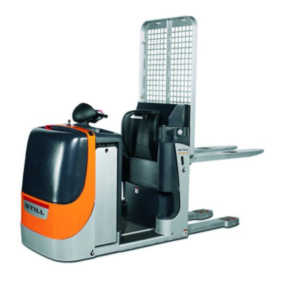
Overviews General view General view 1045_000_001 Battery connector Battery Tiller (cockpit) Brake Pedestrian mode traction button (option) Drive motor Backrest Gearbox Pedestrian mode traction button (option) Traction wheel Load wheel Steering motor Forks Stabiliser wheel Hydraulic oil tank Lift cylinder AC controller Pump motor Platform... -
Page 41: Controls And Display
Overviews Controls and display Controls and display View of the control elements 1044_000-008 Cubby hole Cubby hole Battery compartment lock Pedestrian mode traction button (option) Tiller Cushion Battery plug Pedestrian mode traction button (option) Presence area Cubby hole 4 499 284 [EN]... -
Page 42: Tiller
Overviews Controls and display Tiller 6 7 8 1044_000-006 Lower button Numbers button Lift button button Hare Horn button Horn button button Lift button Tortoise (scrolling) button Lower button PRG ↑ Numbers button Handle Display Travel control Emergency brake switch (ON) button Numbers button... -
Page 43: Marking Positions
Overviews Marking positions Marking positions Location of plates and labels 1044_921-001 Warning label Cold store operation label (option) Manufacturer’s logo and product code Manufacturer’s logo Manufacturer’s plate Customer’s logo (option) Hook symbol Warning label Warning label "Do not attach lifting gear here" label "Do not mount"... -
Page 44: Data Plate
Overviews Options and variants Data plate NOTE Please indicate the serial no. for all technical enquiries. 1044_921-002 Model Manufacturer Serial no. Year of manufacture Unladen weight (without battery) in kg Maximum battery weight Minimum battery weight Additional weight (ballast) in kg Nominal power rating in kW Battery voltage V Rated capacity in kg... -
Page 45: Overview Of Accessories
Overviews Options and variants • Battery charge indicator (for lead battery) with service interval indicator • Cold store model • Document holder • Data input terminal • Customer’s logo • Guards (various types) • FleetManager Overview of accessories • Master code (factory setting "1 2 3 4") •... - Page 46 Overviews Options and variants 4 499 284 [EN]...
-
Page 47: Operation
Operation... -
Page 48: Intended Use Of The Trucks
Operation Intended use of the trucks Intended use of the trucks CAUTION This machine is designed for order picking (coll- ecting and gathering together items stored in the warehouse before dispatch), horizontal transport tasks and entering and removing pallets to and from stock. -
Page 49: Checks Before Driving
Operation Checks and actions prior to use Checks before driving Before starting up, make sure that the truck is in a safe condition: – No visible damage (e.g. deformation, cracks, heavy wear) to forks (1) and other load lifting devices, hair crack(s). CAUTION Have damaged forks repaired or replaced by our after-sales service. -
Page 50: Connecting The Battery Plug (Charging Station)
Operation Commissioning Connecting the battery plug (charg- ing station) – Disconnect the battery socket (1) from the charging station and insert into the plug on the truck. 1044_606-013 Commissioning Turning on the truck NOTE The pallet truck is equipped with a digital con- trol and is taken into operation by entering a driver code. -
Page 51: Entering The Driver Code
Operation Commissioning Entering the driver code – Press the (ON) button (6). The mes- sage (8) will appear in the display (4) CodE and disappear after approx. 1 s. This is the prompt to enter your valid 4-digit driver code. Enter the code in the same way as entering characters on a mobile phone. -
Page 52: Hour Meter
Operation Commissioning – The number is deleted, the flashing line cursor (9) appears again. The code number can be re-entered. – After the 4th number is entered, confirm the input by depressing the button (5). PRG ↲ The manufacturer’s name appears briefly in the display. -
Page 53: Battery Charge
Operation Commissioning Battery charge – Press the (scrolling) button (4) to PRG ↑ display the available battery charge (3). NOTE After the battery is connected, the correct state of charge appears only after about 1 minute. The charge is shown in per cent and changes in steps of 5 %. -
Page 54: Display Of Time To Next Servicing
Operation Commissioning Display of time to next servicing – Press the (scrolling) button (4) to PRG ↑ display the time remaining until the next scheduled servicing. The time is shown in hours (6) and with the symbol of a span- ner (5). -
Page 55: Checking The Presence Area And Brake
Operation Commissioning Checking the presence area and brake – Drive the truck. – Leave the presence area (8). The truck will brake to a stop. 1044_001-009 Checking the emergency brake – Drive the truck slowly using the traction control (4). –... -
Page 56: Driving
Operation Driving Driving Driving safety instructions Driving conduct The driver must follow the public rules of the road when driving in company traffic. The speed must be appropriate to the local con- ditions. For example, the driver must drive slowly around corners, in tight passageways, when driving through swing-doors, at blind spots, or on uneven surfaces. -
Page 57: Before Driving
Operation Driving Before driving Dimensions of roadways and aisles The dimensions and aisle widths contained in section description apply under established conditions to ensure safe driving. Check, when necessary, if a wider aisle is required when the load dimensions differ. The required aisle widths (Ast) depend on the dimensions of the load and may be calculated following the formula: Ast = Wa - X + Length of... -
Page 58: Emergency Stop Procedure
Operation Driving Rules for roadways and work area Only the roads released for traffic by the op- erator or his representative may be driven on. The roadways must be free of obstacles. The load may only be stacked and stored at the appropriate places. -
Page 59: Persons In The Danger Area
Operation Driving WARNING Danger of personal injury Do not step on the forks. WARNING Persons can be injured in the danger zone of the truck. No person, except the driver in his normal operating position, may stand in the danger zone of the truck. If persons refuse to leave the danger zone despite warnings, stop working with the truck immediately and secure it against use by unauthorized persons. -
Page 60: Driving In Rider Mode
Operation Driving Driving in rider mode – Step on the platform with both feet and step on the presence area (1). NOTE The pallet truck is turned on. WARNING There should be no objects lying on the floor of the driver’s platform, whose weight could activate the dead man’s switch under the mat. -
Page 61: Selecting The Driving Mode
Operation Driving Driving forward – Depress the top part of the throttle (2) or (3) with the thumb. – Truck speed is increased by depressing the travel control further. – When the travel control is released, the truck is braked electrically. Reversing –... -
Page 62: Driving, Pedestrian Operation With Tiller, Slow Approach With Drive Switch
Operation Driving Driving, pedestrian operation with tiller, slow approach with drive switch – From the side, grip the handle (1) or (4) on the tiller. NOTE The lift truck is switched on. CAUTION Take care when operating, especially if the user is not familiar with using this function. - Page 63 Operation Driving Backwards driving – Press the lower part of the drive switch with your thumb. – The speed of the fork lift truck increases as you push the traction switch further, up to a limit of 6 km/h. – When the traction switch is released, the fork lift truck brakes electrically.
-
Page 64: Driving, Pedestrian Operation With Push Button
Operation Driving Driving, pedestrian operation with push button NOTE The fork lift truck is fitted with push buttons (1) and (2) on both sides of the seat backrest, enabling the truck to be driven in pedestrian mode from either side. The speed is reduced; the tiller (3) can be used at any time to steer so that the truck keeps going forward in a straight line. -
Page 65: Steering
Operation Driving CAUTION The speed cannot be adjusted. The driver must walk alongside the fork lift truck. – Release push button (4) to stop the truck. The forklift truck will come to a stop. Steering The truck is steered by turning the tiller in range (1). -
Page 66: Brakes
Operation Driving Brakes WARNING The floor surface properties influence the driving and braking behaviour of your truck. Therefore take this into account when driving and braking. Soft braking (regenerative braking) NOTE The truck is braked electrically. The battery is charged by regenerative braking. –... -
Page 67: Emergency Stop Brake
Operation Driving – Release the pedestrian mode traction but- ton (4) or (5). Average braking – Operate travel control (1) or (2) in the oppo- site direction. 1044_501-007 Emergency stop brake CAUTION This brake may only be used in an emergency. –... -
Page 68: Parking Brake
Operation Driving Parking brake – Release traction control (1) or (2). The truck is braked by the electromagnetic brake. 1044_501-009 Automatic shutdown NOTE If you leave the truck with the control turned on, it will be shut off automatically after approx. 15 minutes. -
Page 69: Lift
Operation Lift Lift Lifting device controls WARNING Risk of injury! Always follow the safety rules exactly ⇒ Chap- ter "Load handling safety rules", P. 5-62. Do not put your hand or step into moving parts (eg mast, sideshift, implements, load lifting device, etc.). -
Page 70: Handling Loads
Operation Handling loads Handling loads Load handling safety rules WARNING DANGER Closely observe the following instructions before picking up loads. Never touch or stand on moving parts of the truck (e.g. lifting device, pushing de- vices, work installations or devices for picking up loads). -
Page 71: Picking Up A Loading Unit
Operation Handling loads Picking up a loading unit In order to guarantee load stability, ensure that the load is balanced and centred on the fork arms and that the fork arms have been sufficiently slid underneath the load. The load should not excessively extend over the fork arms , nor should the fork arms excessively protrude out from the load. -
Page 72: Palletising A Load
Operation Handling loads the area within the range of falling loads or a descending working device. WARNING Danger of personal injury Do not step on the forks. WARNING Persons can be injured in the danger zone of the truck. No person, except the driver in his normal operating position, may stand in the danger zone of the truck. -
Page 73: Transporting Pallets Or Other Containers
Operation Handling loads Transporting pallets or other contain- Under normal circumstances, unit loads (e.g. pallets) should be transported individually. Simultaneous transport of more than one unit load is only permitted • on instruction of the supervisor and • if the technical requirements are met. The driver must satisfy himself that the load is in proper condition. -
Page 74: Driving On Gradients
Operation Handling loads Driving on gradients When driving on gradients, the load must be positioned on the uphill side. It is only permit- ted to drive on gradients which are identified as suitable for traffic and which can be safely negotiated. -
Page 75: Entering Lifts
Operation Handling loads Entering lifts The driver may only enter lifts with a sufficient load capacity and with the permission of the operator. Inside the lift, the truck must be se- cured so that no part of it will come into contact with the wall of the lift shaft. -
Page 76: Cold Store Use
Operation Cold store use Cold store use Designation Your truck is fitted with special equipment for use in cold stores. It can be used for two oper- ating ranges and carries a cold store label. The cold store equipment for the truck con- sists of using specialised oils (for the hydraulic installation and the gears) suitable for cold stores. - Page 77 Operation Cold store use – Drive the truck for approximately 5 minutes and operate the brakes several times to ensure the truck operates safely. – Operate all the lifting functions several times. This warming up phase is required to allow the oil to reach operating temperature. Operating range 1 Permanent use in areas with temperatures of–5 °C and for short periods of time down to...
-
Page 78: Using The Digicode Control
Operation Using the Digicode control Using the Digicode control Digicode control Access to the electronic control is granted with three different codes: • Driver’s code • master code • service code Driver’s code The driver’s code consists of four digits and must be created by the Pool Manager. -
Page 79: Adding The Master Code
Operation Using the Digicode control Service code The service code is only intended for the after- sales service. It allows the diagnosis of the truck for inspections and the access to the driver’s and master code. Adding the master code NOTE The pallet truck is turned off, the battery is connected. -
Page 80: Deleting A Master Code
Operation Using the Digicode control – Confirm with the (enter) button (4). PRG ↲ 1044_505-012 A flashing line cursor (8) will appear in the display. – Enter the desired new 4-digit master code with the buttons (1), (2) or (3) as described above. -
Page 81: Buttons 123 (1), 456 (2) And
Operation Using the Digicode control – Press the (ON) button (5). – Enter the valid 4-digit master code with the buttons (1), (2) and (3). 1044_505-009 – Scroll with the (scrolling) button (6) PRG ↑ 1044_505-010 until (7) appears in the display. –... -
Page 82: Adding A Driver's Code
Operation Using the Digicode control – Confirm with the (enter) button (4) PRG ↲ 1044_505-013 until the master code (9) to be deleted blinks (an example is shown). – Then release the button. (10) will ap- 1044_505-015 pear again in the display. –... -
Page 83: 1044_505-011
Operation Using the Digicode control – Scroll with the (scrolling) button (6) PRG ↑ 1044_505-016 until (7) appears in the display. USEr – Confirm with the (enter) button (4) PRG ↲ 1044_505-011 until (10) appears in the display. – Confirm with the (enter) button (4). -
Page 84: Deleting A Driver's Code
Operation Using the Digicode control Deleting a driver’s code NOTE The pallet truck is turned off, the battery is connected. – Press the (ON) button (5). – Enter the valid 4-digit master code with the buttons (1), (2) and (3). 1044_505-009 –... - Page 85 Operation Using the Digicode control – Confirm with the (enter) button (4) PRG ↲ 1044_505-013 until the driver’s code (9) to be deleted blinks (an example is shown). – Then release the button. (10) will ap- 1044_505-015 pear again in the display. –...
-
Page 86: Fault Displays
Operation Fault displays Fault displays Error code 11 12 If an error code such as (15) appears, E380 shut the truck off by pressing button (10) and repeat the start-up ⇒ Chapter "Commission- ing", P. 42. If the error code persists, call your Service. -
Page 87: Handling The Truck In Specific Situations
Operation Handling the truck in specific situations Error code Description Action button operated at power-up. Release the button (11). E379 Hare Hare Right button operated at power-up. Release the right button (12). E380 Horn Horn Release the right button Lowering Right button operated at power-up. -
Page 88: Hoisting The Truck
Operation Handling the battery Hoisting the truck CAUTION Only use a lifting sling and crane with sufficient lifting capacity. See the type plate for the hoisting weight. – To hoist the truck with a crane, attach slings in the positions (3) identified by the hook symbol. -
Page 89: Battery Weight And Dimensions
Operation Handling the battery Safe parking When the battery is being serviced, the pallet stacker must be parked safely. The truck may only be operated after the battery cover is closed and the battery connector plugged in. Battery weight and dimensions The battery weight and the dimensions affect the stability of the lift truck. - Page 90 Operation Handling the battery – Remove the female battery connector (1). 1044_001-006 – Insert the key (2) into the battery lock and turn it 180°. Press the battery lock. The battery cover (3) is unlocked and can be opened to the rear. 1044_606-002 4 499 284 [EN]...
- Page 91 Operation Handling the battery – Turn the battery latch (4) up 90°. 1044_606-003 Closing WARNING Danger of squeezing cables. When closing the cover, be sure that there is nothing between the bonnet and chassis edge. – Reconnect the battery female connector (3).
-
Page 92: Battery Replacement
Operation Handling the battery – Turn the battery compartment key (5) 180° and remove it. 1044_606-015 Battery replacement There are 2 ways of replacing the battery: 1. Vertically with a lifting tackle (all trucks) 2. With a lateral battery removal trolley (op- tion) To avoid short circuits, cover batteries with unprotected terminals or connectors with a... -
Page 93: Battery Replacement With Crane
Operation Handling the battery Battery replacement with crane – Disconnect the battery connector. – Open the battery cover. – Release the battery. – Attach the battery (6) to a suitable lifting tackle (5). – The lifting tackle should exercise a vertical pull so that the battery tray is not squeezed together. -
Page 94: Servicing The Battery
Operation Handling the battery Servicing the battery Observe the applicable national regulations started when the battery cover is closed and for the installation and operation of battery the battery plug connected. charging units. Obey the operating instruc- tions for the charging unit or charger and the Battery servicing battery. -
Page 95: Putting Out Of Commission
Operation Putting out of commission Putting out of commission Parking the truck securely WARNING Do not park the truck on gradients. In special cases secure the truck with chocks. – Lower the forks (1) to the ground. WARNING – Do not leave the truck with the load elevated. 1044_842-001 –... -
Page 96: Storage
Operation Storage Storage Measures to take if the lift truck is to be shut down for a long time If the lift truck is to be shut down for a long time, the following measures must be taken to protect against corrosion. If the lift truck is to be shut down for more than two months, it must be parked in a clean and dry area. -
Page 97: Recommissioning After Taking Out Of Service
Operation Storage Recommissioning after taking out of service If the truck has been out of service for over six months, it must be inspected carefully be- fore recommissioning. Similar to the accident prevention check, the inspection should also cover all points relating to truck safety. –... - Page 98 Operation Storage 4 499 284 [EN]...
-
Page 99: Maintenance
Maintenance... -
Page 100: General Maintenance Information
Maintenance General maintenance information General maintenance information General These instructions contain all the information required to perform the routine maintenance on your fork truck. Carry out the maintenance at the correct interval according to the main- tenance chart to keep your truck ready for operation, maintain its efficiency and prolong its service life and to benefit from the warranty. -
Page 101: Staff Training And Qualifications For Maintenance And Repairs
Maintenance General maintenance information Staff training and qualifications for maintenance and repairs Only qualified and authorized staff may carry out the maintenance. The annual inspection must be performed by an expert. The expert must provide his opinion and safety assess- ment irrespective of the internal and finan- cial circumstances of the company. -
Page 102: List Of Inspections
Maintenance General maintenance information List of inspections Maintenance and lubrication 1. daily 2. carry out maintenance according to the hour meter (bold typeface) E.g. after 3000 hours of service all the "500 and 1000 hour" maintenance and lubrication work should be carried out. After 9000 hours of service, continue as above, therefore instead of 500 hours: 9500 hours of service. -
Page 103: Maintenance And Inspection Intervals
Maintenance General maintenance information Maintenance and inspection intervals 1045_010-001 The services must be performed according to the following maintenance intervals. Item Maintenance work Cleaning the truck 2, 7, 9 Service the wheels and rollers as required Service the battery Service the braking system Service the gearbox Service the hydraulic system 6, 10, 12... -
Page 104: Ordering Spare Parts
Maintenance General maintenance information Ordering spare parts Spare parts are supplied by our Service. Re- fer to the Parts List for the required ordering information. Only use spare parts as specified by the manu- facturer. Due to insufficient quality or incorrect assignment, the use of parts not approved by the manufacturer can increase the risk of ac- cidents. -
Page 105: Table Of Maintenance Data
Maintenance General maintenance information Table of maintenance data Assembly Aids/Lubricants Symbol Specification Dimension Battery Distilled water required - Insulation 1000 Ohm resistance min.against body Controls/joints Lithium base NLGI Multi S2 required grease, gear oil MIL-L-2105, TOTAL API:GL4 approx. Hydraulic Hydraulic oil DIN 51524 P2, HLP Up to ZS46... -
Page 106: Maintenance Safety Instructions
Maintenance Maintenance safety instructions Maintenance safety instructions Safety measures for maintenance and repair To prevent accidents during maintenance and repair, perform all necessary safety measures such as: – Ensure that the truck is secured against in- advertent movement or accidental starting (disconnect the battery connector). - Page 107 Maintenance Preparation for maintenance up the equipment, secure it against sliding or tipping with suitable means (wedges, wooden blocks). Jacking up the truck The truck must be jacked up for various ser- vices. Always be sure that: • the load capacity of the jack is sufficient, •...
- Page 108 Maintenance Preparation for maintenance Removing the bonnet The bonnet must be removed before servic- ing. Proceed as follows: – Remove 2 screws (1) and (2). – Remove the bonnet (3). CAUTION Do not damage electric cables. 1044_001-003 Installing the bonnet –...
-
Page 109: Cleaning
Maintenance Cleaning Cleaning Cleaning the truck Washing instructions – Always park the truck as specified. – Disconnect the battery plug (1). CAUTION – Disconnect the battery plug before washing the truck. Washing the exterior of the truck WARNING Do not use inflammable fluids for cleaning. Ob- serve the above safety precautions for preventing sparks through shorts (disconnecting the battery plug). -
Page 110: Maintenance As Required
Maintenance Maintenance as required Cleaning the electrical system WARNING Do not spray directly onto the electric motors, other electric components, brakes and bearings. NOTE Use only dry cleaning agents suited for this purpose. Do not remove shielding covers, etc. – Clean and blow dry electrical components using a non-metallic brush and a weak jet of air. -
Page 111: Servicing The Battery
Maintenance Maintenance as required Adjusting the support wheel NOTE The wear of the traction wheel can be partially compensated by adjusting the support wheel. – Secure the pallet truck and place the trac- tion wheel on a support 5 - 8 mm thick. –... - Page 112 Maintenance Maintenance as required greased with terminal grease and screwed on securely. Battery charging During charging, keep the surface of the bat- tery cells exposed in order to provide sufficient ventilation. Do not place any metallic objects on the batteries. While charging the battery keep battery cover open.
-
Page 113: Charging The Lead Battery
Maintenance Maintenance as required Charging the lead battery WARNING The battery could be damaged, shorted or an ex- plosion could occur. Do not place any metallic objects or tools on the battery. No naked lights, no smoking permitted! WARNING The electrolyte (diluted sulphuric acid) is poisonous 1044_606-008 and caustic! Follow the safety precautions for handling battery... - Page 114 Maintenance Maintenance as required – Connect the battery plug (2) to the connec- tor of the charger unit. NOTE Please follow the information in the operating instructions for the battery and the charging station (equalising charge). WARNING The gases released during charging are explosive. –...
-
Page 115: Checking Operation Of The Brake, Checking The Emergency Brake
Maintenance Maintenance as required Checking operation of the brake, checking the emergency brake – Drive the truck. – Leave presence area (5). The truck will brake to a stop. – Drive the truck slowly with the traction con- trol (2). –... -
Page 116: Fuses
Maintenance Maintenance as required Fuses CAUTION – Before performing any work on the electrical installation, remove any power from the system by disconnecting the battery connector. – Remove the 2 screws (1) and (2). – Remove the front cover (3). The following fuses are located on the fuse carrier: F1 Line fuse 400 A... -
Page 117: Maintenance Every 500 Hours
Maintenance Maintenance every 500 hours Maintenance every 500 hours Other tasks – Carry out the services of the maintenance as required, see ⇒ Chapter "Maintenance as required", P. 102. Checking the gearbox oil level NOTE The truck must stand on level ground. –... -
Page 118: Checking The Hydraulic Oil Level, Hydraulic System For Leaks
Maintenance Maintenance every 500 hours Checking the hydraulic oil level, hy- draulic system for leaks – Remove the front cover. – Check the pipe and hose connections for leaks (traces of oil). – Lower the forks. – Check the oil level on the reservoir (2). The oil level (3) should be up to the middle of the filler elbow. -
Page 119: Servicing The Electric Motors
Maintenance Maintenance every 500 hours Servicing the electric motors Checking the cable connections – Check the traction motor (3) and pump mo- tor (1) and steering motor (2) cables for secure connection, condition and insula- tion. NOTE Corroded connections and broken cables lead to drops in voltage, leading to malfunctions. - Page 120 Maintenance Maintenance every 500 hours Change the pump motor and the steering motor brushes – Shut down the pallet truck, remove the bat- tery connector. Remove the front bonnet. To access the motor brushes: – Remove the pump motor screws (6) and take off the cap (5).
-
Page 121: Servicing The Electrical System
Maintenance Maintenance every 500 hours – Close the cover band (4) again, refit the cap (5). – Refit the removed parts. 1044_110-005 Servicing the electrical system Checking fuses and cable connections DANGER – Before starting the following work, park the truck and disconnect the battery plug. -
Page 122: Servicing The Braking System
Maintenance Maintenance every 500 hours Servicing the braking system Checking the air gap – Release the brake. – Measure the gap (1) with a feeler gauge. Min air gap: 0.3 mm Max air gap: 0.8 mm WARNING – Renew the brake disk, when the max. gap is reached. -
Page 123: Checking The Forks
Maintenance Maintenance every 500 hours Checking the forks Checking the condition of the forks – Check the forks (1) for signs of deformation, cracks, strong traces of use or hair cracks. CAUTION – Have the forks repaired and replaced by your after-sales service. - Page 124 Maintenance Maintenance every 500 hours 4 499 284 [EN]...
-
Page 125: Annual Maintenance
Maintenance Annual maintenance Annual maintenance Work that must also be carried out – Carry out maintenance work as neces- sary, see ⇒ Chapter "Maintenance as re- quired", P. 102. – Carry out 500-hour maintenance, see ⇒ Chapter "Maintenance every 500 hours", P. -
Page 126: Performing The Accident Prevention Check
Maintenance Annual maintenance Performing the accident prevention check The vehicle must be tested (at least once a year) by an expert. jährliche Prüfung This annual test by an expert must cover the gem. UVV Mängel siehe Prüfbuch condition of the assemblies and equipment letzte Prüfung and the completeness and efficacy of the safety features. -
Page 127: Maintenance Every 2000 Hours
Maintenance Maintenance every 2000 hours Maintenance every 2000 hours Work that must also be carried out – Carry out maintenance work as neces- sary, see ⇒ Chapter "Maintenance as re- quired", P. 102. – Carry out 500-hour maintenance, see ⇒ Chapter "Maintenance every 500 hours", P. - Page 128 Maintenance Maintenance every 2000 hours – Remove and renew the hydraulic oil filter screen (5) at the pump motor. – Install a new seal (4). – Mount a new hydraulic oil reservoir on the pump motor and install both together. 1044_700-004 –...
-
Page 129: Checking And Cleaning The Battery
Maintenance Maintenance every 2000 hours Checking and cleaning the battery WARNING Explosion or short can occur! No smoking, no naked lights and do not put any metal objects on the battery. 1044_606-012 Servicing the battery according to the manufacturer’s instructions WARNING Risk of personal injury due to arcing! –... -
Page 130: Performing The Accident Prevention Check
Maintenance Maintenance every 2000 hours Performing the accident prevention check The vehicle must be tested (at least once a year) by an expert. jährliche Prüfung This annual test by an expert must cover the gem. UVV Mängel siehe Prüfbuch condition of the assemblies and equipment letzte Prüfung and the completeness and efficacy of the safety features. -
Page 131: Maintenance Every 5000 Hours
Maintenance Maintenance every 5000 hours Maintenance every 5000 hours Work that must also be carried out – Carry out maintenance work as neces- sary, see ⇒ Chapter "Maintenance as re- quired", P. 102. – Carry out 500-hour maintenance, see ⇒ Chapter "Maintenance every 500 hours", P. - Page 132 Maintenance Maintenance every 5000 hours 4 499 284 [EN]...
-
Page 133: Technical Data
Technical data... -
Page 134: Dimensions
Technical data Dimensions Dimensions 4 499 284 [EN]... -
Page 135: Vdi Data Sheet
Technical data VDI data sheet VDI data sheet Identification CX-M 10 Manufacturer’s model designation STILL GmbH Fixed Platform Drive: Battery, Diesel, petrol, LP Battery gas, mains Operator type: Manual, walkie, order picker driver standing, driver seated, order picker 1000 Load capacity/hoisted load... - Page 136 Technical data VDI data sheet Overall dimensions CX-M 10 Height, mast lowered h1 (mm) 1375 h3 (mm) Lift Overall height, mast extended h4 (mm) 2075 Height of driver’s platform h7 (mm) Tiller height h14 (mm) min/max 1165 Fork height h13 (mm)
-
Page 137: Wheels And Tyres
Technical data Wheels and tyres Motor CX-M 10 Drive motor, performance, S2 = 60 min Lift motor, performance, S3 = Battery acc. to DIN 43531/35/36 IEC 254 - 2;B A, B, C, no Battery voltage U (V) Battery capacity K5 (Ah) - Page 138 Technical data Battery tray Forks length Distance X 450 Ah 600 Ah 1190 1005 2430 2516 1450 1265 2690 2776 1650 1105 2530 2616 2150 1605 3030 3116 2390 1845 3270 3356 2390 1615 3040 3126 2900 2125 3550 3636 3100 2125 3550...
- Page 139 Index EC declaration of conformity ... 2 Electrical insulation test ... . . 22 Approved applications ....10 Emissions .
- Page 140 Index Overview of accessories ... . . 37 Site of operation ....11 Specialist .
- Page 142 Still GmbH Berzeliusstrasse 10 D-22113 Hamburg Ident no. 4 499 284 EN...
-
Page 143: Annex
Operating Instructions Floor-level order picker CX-M 10 1045 Ident no. 4 499 284 - 08.09 - EN Annex... -
Page 145: Diagrams
Diagrams... -
Page 146: Hydraulic System
Diagrams Hydraulic system Hydraulic system Hydraulic diagram 4 499 284 [EN]... - Page 147 Diagrams Hydraulic system Lift cylinder Flow restrictor (throttle) Oil screen Non-return valve Hydraulic block Hydraulic oil tank Lift pump Filter Lowering solenoid valve Pump motor Pressure limiter 4 499 284 [EN]...
-
Page 148: Electrical System
Diagrams Electrical system Electrical system Circuit diagram Standard equipment and options 4 499 284 [EN]... -
Page 149: Circuit Diagram
Diagrams Electrical system Circuit diagram Driving platform option 4 499 284 [EN]... -
Page 150: Description Of Components
Diagrams Electrical system Description of components Compo- Compo- Compo- Standard equipment and options Designation Designation Designation nent nent nent NOTE Traction or line contactor Loading frame height sensor Traction names Forward travel or forward/re- The units listed below are not necessarily Pump contactor Anti-foot compression sensor verse travel throttle valves... - Page 151 Diagrams Electrical system Compo- Compo- Compo- Compo- Designation Designation Designation Designation nent nent nent nent Driving platform raising solenoid Various connectors Various connectors Lowering solenoid valve valve Various connectors Connector, tiller case 1 Brake Solenoid valve, disconnection Various connectors Connector, tiller case 2 Loading frame solenoid valve of hydraulic accumulator Various connectors...
- Page 152 Still GmbH Berzeliusstrasse 10 D-22113 Hamburg Ident no. 4 499 284 EN...
Need help?
Do you have a question about the CX-M 10 and is the answer not in the manual?
Questions and answers