
Related Manuals for Snorkel S3215L


Summary of Contents for Snorkel S3215L
- Page 1 OPERATOR’S MANUAL Part Number 1500834 ANSI/CSA/CE/AS/NZS Serial number 000017, 000019 and after February 2020 Replaces January 2020 Original Instructions...
-
Page 2: Proposition 65 Warning
The aerial platform is not electrically insulated. Death or serious injury will result from contact with, or inadequate clearance from, an energized conductor. Do not go closer than the minimum safe approach distance as defined by the Minimum Safe Approach Distance section in Chapter 3–Safety. Regard all conductors as energized. - Page 3 ADANGER Do NOT Go Closer Than The Do NOT Operate Outside Do NOT Operate in Do NOT Add Anything That Minimum Safe Approach Distance During a Thunderstorm Windy or Gusty Conditions Will Increase Wind Loading Do NOT Drive an Elevated MEWP on Do NOT Operate an Elevated Do NOT Operate a Stowed Do NOT Operate an Elevated MEWP...
- Page 4 Fall Restraint Lanyard Anchor Points All fall restraint lanyard anchor points on Snorkel aerial work platforms have been tested with a force of 3,650 lbs (16.3 kN) per person. See below examples of anchor points used on Snorkel machines with their corresponding per person rating.
-
Page 5: Safety Rules
NEVER charge batteries near sparks or open flame. Charging batteries emit explosive hydrogen gas. Modifications to the aerial work platform are prohibited or permissible only at the approval by Snorkel. AFTER USE, secure the work platform from unauthorized use by turning the keyswitch off and removing key. -
Page 7: Table Of Contents
General Maintenance ..........25 Charging ..............25 Chapter 2 – Specifications Component Identification ..........3 Chapter 7 – Controls General Specifications – S3215L .......4 Battery Disconnect ...........27 General Specifications – S3215E .......5 Lower Controls ............27 General Specifications – S3219E .......6 Emergency Stop Button ........27 General Specifications –... - Page 8 Troubleshooting Chart ..........63 Raising and Lowering ..........46 Lowering Interrupt – CE/AS/NZS ......46 Appendix A – Glossary Overload Protection ..........47 Extending ..............47 Appendix B – EC Declaration of Conformity Fold Down Guardrails ..........47 Appendix C – Inspection Checklists Limited Warranty S3215L/S3215E/S3219E/S3220E/S3226E/S4726E/S4732E – 1500834...
-
Page 9: Chapter 1 - Introduction
Additional copies of this manual may be ordered from Snorkel. Supply the model and manual part number from The standard machine includes the following features: the front cover to assure that the correct manual will be supplied. -
Page 10: Maintenance
Inspection Record (PDIR). The PDIR inspection the aerial platform must be qualified to do so. Following is performed by Snorkel, or it’s agent, before the machine the daily prestart inspection in this Operator’s Manual will is delivered to the customer. A completed PDIR form can help keep the aerial platform in optimum working condi- be obtained, by request, from the sales agent. -
Page 11: Chapter 2 - Specifications
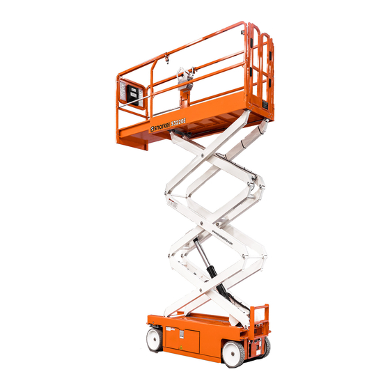
Chapter 2 – Specifications Component Identification Platform Extension Platform All Models Except S3215L Toeboards Emergency Lowering Lever S3215L/S3215E/S3219E Entry Serial Step Number Drive and Steer Wheels Groundstrap Control Valve Tray Battery Tray Tie-Down/Lifting Lugs Freewheeling Valve/Brake Release Valve Hand Pump/Diagnostic Display... -
Page 12: General Specifications - S3215L
Chapter 2 – Specifications General Specifications – S3215L Drive System Aerial Platform Working height 21′ (6.6 m) Standard Two-wheel drive Maximum platform height 15′ (4.6 m) Gradeability Turning radius Maximum drive height 15′ (4.6 m) 4″ (10.16 cm) Inside Drive/Lift Level Sensor Interlock Outside 64.25″... -
Page 13: General Specifications - S3215E
Platform lower than 6′ (1.8 m) 0 to 2 mph (0 to 3.2 km/h) Heavy Duty – intended life 100,000 load cycles Low Drive Platform higher than 6′ (1.8 m) 0 to 0.4 mph (0 to 0.6 km/h) S3215L/S3215E/S3219E/S3220E/S3226E/S4726E/S4732E – 1500834... -
Page 14: General Specifications - S3219E
Platform lower 30 to 36 seconds High Drive Platform lower than 6′ (1.8 m) 0 to 2 mph (0 to 3.2 km/h) Low Drive Platform higher than 6′ (1.8 m) 0 to 0.4 mph (0 to 0.6 km/h) S3215L/S3215E/S3219E/S3220E/S3226E/S4726E/S4732E – 1500834... -
Page 15: General Specifications - S3220E
Platform lower than 6′ (1.8 m) 0 to 2 mph (0 to 3.2 km/h) Heavy Duty – intended life 100,000 load cycles Low Drive Platform higher than 6′ (1.8 m) 0 to 0.4 mph (0 to 0.6 km/h) S3215L/S3215E/S3219E/S3220E/S3226E/S4726E/S4732E – 1500834... -
Page 16: General Specifications - S3226E
0 to 2 mph (0 to 3.2 km/h) Low Drive Platform higher than 6′ (1.8 m) 0 to 0.4 mph (0 to 0.6 km/h) * Refer to Chapter 4 – Safety Devices, Progressive Tilt – S3226E Only. S3215L/S3215E/S3219E/S3220E/S3226E/S4726E/S4732E – 1500834... -
Page 17: General Specifications - S4726E
Heavy Duty – intended life 100,000 load cycles High Drive Platform lower than 6′ (1.8 m) 0 to 2 mph (0 to 3.2 km/h) Low Drive Platform higher than 6′ (1.8 m) 0 to 0.4 mph (0 to 0.6 km/h) S3215L/S3215E/S3219E/S3220E/S3226E/S4726E/S4732E – 1500834... -
Page 18: General Specifications - S4732E
Platform lower than 6′ (1.8 m) 0 to 2 mph (0 to 3.2 km/h) Low Drive Platform higher than 6′ (1.8 m) 0 to 0.4 mph (0 to 0.6 km/h) * Refer to Serial Number placard at rear of machine. S3215L/S3215E/S3219E/S3220E/S3226E/S4726E/S4732E – 1500834... -
Page 19: Chapter 3 - Safety
Over 200kV to 350Kv 6.10 Over 350kV to 500kV 7.62 Over 500kV to 750kV 10.67 Over 750kV to 1000kV 13.72 Table 1 – Minimum Safe Approach Distance Denotes prohibited zone Figure 3 – Minimum Safe Approach Distance S3215L/S3215E/S3219E/S3220E/S3226E/S4726E/S4732E – 1500834... -
Page 20: Minimum Safe Approach Distance - As/Nzs
Tree branches move. Power lines whistle. It is difficult to open an 10,8~13,9 38,9~50,0 35.5~45.5 24.5~31 umbrella. 13,9~17,2 50,0~61,9 Whole trees sway. It is difficult to walk against the wind. 45.5~56.5 31.~38.5 Figure 2 – Beaufort Scale S3215L/S3215E/S3219E/S3220E/S3226E/S4726E/S4732E – 1500834... -
Page 21: Operation
Do not engage in any form of horseplay or permit rid- or uneven ground, or other tip-over hazard. Do not ers any place other than in the platform. raise the platform outdoors in wind speeds above 28 mph (12.5 m/s). S3215L/S3215E/S3219E/S3220E/S3226E/S4726E/S4732E – 1500834... -
Page 22: Electrical System
Danger Hydraulic fluid escaping under pressure can have unless the application is approved in writing by Snorkel. enough force to inject fluid into the flesh. Serious Do not use the aerial platform as a crane, hoist, jack or infection or reaction will result if medical treatment is not given immediately. - Page 23 Operate machine only on surfaces capable of supporting Modifications to the aerial work platform are prohibited or wheel loads. permissible only at the approval by Snorkel. Never operate the machine when wind speeds exceed After use, secure the work platform from unauthorized use the machine’s wind rating.
- Page 24 Chapter 3 – Safety S3215L/S3215E/S3219E/S3220E/S3226E/S4726E/S4732E – 1500834...
-
Page 25: Chapter 4 - Safety Devices
On CE/AS/NZS machines, if one emergency stop is engaged the machine will not operate. At the upper controls, the emergency stop is a two-posi- tion red push button (refer to Figure 4.2). S3215L/S3215E/S3219E/S3220E/S3226E/S4726E/S4732E – 1500834... -
Page 26: Drive Motion Alarm
This protection system limits the tilt angle if a wheel is driven into a drop-off or hole. This greatly reduces the likelihood of the aerial platform tipping over. The pothole protection system is for added protection and does not justify operating near drop-offs or holes. S3215L/S3215E/S3219E/S3220E/S3226E/S4726E/S4732E – 1500834... -
Page 27: Lowering Alarm
The lever for the S3215L/S3215E/S3219E is mounted at Safety Prop the front of the aerial platform (refer to Figure 4.6). The safety prop (refer to Figure 4.8) is used to support the scissors structure when access to the scissors arm components or the chassis is required. -
Page 28: Guardrails
Refer to the ma- chine general specifications for the specific level sensor Center the control in neutral to reset the lowering function, settings. then continue to lower the platform. S3215L/S3215E/S3219E/S3220E/S3226E/S4726E/S4732E – 1500834... -
Page 29: Horn
Snorkel Guard Figure 4.11 – Upper Controls The optional Snorkel Guard (refer to Figure 4.11) is a mechanically activated guarding system which offers an The lower controls are not affected by the Snorkel Guard additional level of protection to the operator at the upper activation. - Page 30 Chapter 4 – Safety Devices S3215L/S3215E/S3219E/S3220E/S3226E/S4726E/S4732E – 1500834...
-
Page 31: Chapter 5 - Gauges And Displays
• 100% green LED solid On – indicates that the charge cycle is complete. Battery Condition Indicator Figure 5.3 – Top of Upper Controls S3215L/S3215E/S3219E/S3220E/S3226E/S4726E/S4732E – 1500834... -
Page 32: Diagnostic Center Display
When the battery disconnect and emergency stop but- ton at the lower controls are in the on position, the LCD display shows: • The accumulated aerial platform operating time • The available battery power to operate the machine. S3215L/S3215E/S3219E/S3220E/S3226E/S4726E/S4732E – 1500834... -
Page 33: Chapter 6 - Batteries
16 hours without the batteries being fully recharged, shut off the charger and have the batteries checked. Fully recharge the batteries, immediately after use. One charging cycle per day is preferred. Fully charged batteries perform best. S3215L/S3215E/S3219E/S3220E/S3226E/S4726E/S4732E – 1500834... - Page 34 Chapter 6 – Batteries S3215L/S3215E/S3219E/S3220E/S3226E/S4726E/S4732E – 1500834...
-
Page 35: Chapter 7 - Controls
The upper controls will not operate while the control selector is in the lower position. Platform Raise/Lower Switch The platform raise/lower switch is used to raise or lower the platform. The switch is spring returned to the center off position. S3215L/S3215E/S3219E/S3220E/S3226E/S4726E/S4732E – 1500834... -
Page 36: Upper Controls
Platform raise/lower and speed controls. If the upper control emergency stop button is engaged, the lower controls can still be used to operate the aerial platform. On CE/AS/NZS machines, if one emergency stop is engaged the machine will not operate. S3215L/S3215E/S3219E/S3220E/S3226E/S4726E/S4732E – 1500834... -
Page 37: Interlock Switch
Pull the button outward to restore power. Push the emergency stop button inward when the pendant is not in use to protect against uninten- tional operation. S3215L/S3215E/S3219E/S3220E/S3226E/S4726E/S4732E – 1500834... -
Page 38: Interlock Button
Override Switch Interlock Button The controls have an interlock button to activate drive When the Snorkel Guard or the platform overload system functions (refer to Figure 7.4). For pendant controls, is activated, the override button (refer to Figure 7.5) is... -
Page 39: Chapter 8 - Prestart Inspection
Dealers, Owners, Users, Operators, reduce the life of the battery. Lessors and Lessees of ANSI/SIA A92.6-2006 Self- Propelled Elevating Work Platforms” is in the manual holder. S3215L/S3215E/S3219E/S3220E/S3226E/S4726E/S4732E – 1500834... -
Page 40: Battery Terminals
Always use the safety prop when the platform is raised before inspecting or performing service or maintenance procedures on the machine. Danger Pinch points exist on the scissors structure. Death or serious injury will result if the scissors structure drops onto personnel working within the scissors S3215L/S3215E/S3219E/S3220E/S3226E/S4726E/S4732E – 1500834... -
Page 41: Cables And Wiring Harness
(refer to Figure 8.6). Some machines Right Side of Chassis may have a fill cap with a dipstick. The fluid must be visible on the dipstick. 2. Make sure the hoses are properly routed to avoid sharp edges, kinking, and scuffing. S3215L/S3215E/S3219E/S3220E/S3226E/S4726E/S4732E – 1500834... -
Page 42: Free-Wheeling Valve
To inspect the tires and wheels: 3. Hold the control select/ground operation switch downward in the lower controls position. 1. Visually inspect the tires. They should be smooth without any cuts, gouges, or missing rubber that might affect aerial platform stability. S3215L/S3215E/S3219E/S3220E/S3226E/S4726E/S4732E – 1500834... -
Page 43: Emergency Stop
9. Raise the platform. When the skid contacts the board, an alarm should sound at approximately 7′ (2 m) plat- form floor height. The alarm should then sound when the platform lift switch is activated. S3215L/S3215E/S3219E/S3220E/S3226E/S4726E/S4732E – 1500834... -
Page 44: Emergency Lowering System
3. Make sure there is nothing in the way to obstruct the platform when it lowers. Stand clear of the scissors The lever for the S3215L/S3215E/S3219E is mounted structure. at the front of the aerial platform (refer to Figure 8.13). -
Page 45: Rollers And Slide Blocks
2. Inspect all of the bolts, nuts, rollpins, collars, and is on a level surface. snap rings. They should all be present, tight, and not damaged in any way. S3215L/S3215E/S3219E/S3220E/S3226E/S4726E/S4732E – 1500834... -
Page 46: Operating Controls
Make Horn sure the upper control panel is securely fastened in- side the platform and facing the front of the machine. Upper Controls – Front Figure 8.19 – Upper Controls S3215L/S3215E/S3219E/S3220E/S3226E/S4726E/S4732E – 1500834... -
Page 47: Emergency Stop
Emergency Stop To test the emergency stop button from the upper con- If the power was on, repair or replace the re- trols: ceptacle. 1. Push the emergency stop button inward to turn off electrical power. S3215L/S3215E/S3219E/S3220E/S3226E/S4726E/S4732E – 1500834... -
Page 48: Flashing Light
4. Replace any missing, damaged, or illegible placards or decals before operating the aerial platform. Placard and decal kits are available from Snorkel. Safety related placards and decals are illustrated on the following pages. Refer to the appropriate decal page in the machine parts manual for specific operational and safety placards and decals. - Page 49 OTHER ACTIONS CAN ALSO CAUSE OTHER ACTIONS CAN ALSO CAUSE THIS MACHINE TO TIP OVER THIS MACHINE TO TIP OVER 1502773 – S3215L DO NOT override safety devices. DO NOT ride platform while machine is on a truck, fork lift or other device.
- Page 50 1. Raise platform until the open height is wide when servicing machine enough to position the safety prop. with platform raised. 2. Place the safety prop in the storage position. 0361259 0361259 Left Side 0074311 (Rod End of Lift Cylinder) 0074311 300700 300700 Front S3215L/S3215E/S3219E/S3220E/S3226E/S4726E/S4732E – 1500834...
-
Page 51: Prestart Inspection Checklist
No damage or deformation. Proper operation Pipe Rack – option No damage or deformation. Proper operation Panel Carrier – option Snorkel Guard – option No damage or deformation. Proper operation No damage or deformation. Proper operation Bumpguard – option No damage or deformation. Proper operation Airline to platform –... - Page 52 Chapter 8 – Prestart Inspection S3215L/S3215E/S3219E/S3220E/S3226E/S4726E/S4732E – 1500834...
-
Page 53: Chapter 9 - Operation
2. Place the battery disconnect switch in the on posi- tion. 3. Switch the control select/ground operation switch upward to the upper controls position. 3. Close and latch the swing-out trays. S3215L/S3215E/S3219E/S3220E/S3226E/S4726E/S4732E – 1500834... -
Page 54: Removable Upper Controls/Side Drive
An optional removable upper control box or a side drive pendant may be provided on the machine. Center the control in neutral to reset the lowering function, then continue to lower the platform. S3215L/S3215E/S3219E/S3220E/S3226E/S4726E/S4732E – 1500834... -
Page 55: Overload Protection
Use extreme care when moving the aerial platform while the fold down 2. While facing the front of the platform, grasp the rails are lowered. platform extension handles, raise them and push S3215L/S3215E/S3219E/S3220E/S3226E/S4726E/S4732E – 1500834... -
Page 56: Driving And Steering
4. To stop drive motion, return the joystick to neutral. If driving the machine, come to a complete stop before switching from Low to High drive range. S3215L/S3215E/S3219E/S3220E/S3226E/S4726E/S4732E – 1500834... -
Page 57: Drive Speeds
If the drive/lift level sensor interlock shuts off the platform hand pump. The diagnostic center LCD display is raise and drive functions, lower the platform and drive to also in this tray. a level surface. S3215L/S3215E/S3219E/S3220E/S3226E/S4726E/S4732E – 1500834... -
Page 58: Electrical Power Outlet
Use the following procedure to load the pipe rack. Figure 9.7 – Rear of Chassis 1. At the front and rear, press on the latch lever to re- lease the latch and unfasten the straps. S3215L/S3215E/S3219E/S3220E/S3226E/S4726E/S4732E – 1500834... -
Page 59: Panel Carrier
Figure 9.10 – Panel Carrier Rated Load The panel carrier is available on the following models: and Platform Capacity Snorkel Guard S3215L The optional Snorkel Guard (refer to Figure 9.11) is a S3215E S3219E mechanically activated guarding system which offers an S3220E... -
Page 60: Override Button
The override button at the upper controls may be used to the on position, and activate the override switch. to override the platform overload and the Snorkel Guard system, when either one is activated. 3. Activate the joystick interlock. -
Page 61: Chapter 10 - Stowing And Transporting
DOT, and/or any other state or federal law are The aerial platform is free to move when the brakes followed. are released. Death or serious injury could result. Re-enable the brakes before operating the aerial platform. S3215L/S3215E/S3219E/S3220E/S3226E/S4726E/S4732E – 1500834... - Page 62 5. Turn the brake release valve counterclockwise to the fully open position. Turn the free-wheeling valve clockwise to the fully closed position. S3215L/S3215E/S3219E/S3220E/S3226E/S4726E/S4732E – 1500834...
-
Page 63: Driving
7. Verify that the drive system and brakes operate 7. Drive the aerial platform on or off the transport vehicle properly before operating the aerial platform. in a straight line through the grade transitions with minimal turning. S3215L/S3215E/S3219E/S3220E/S3226E/S4726E/S4732E – 1500834... -
Page 64: Hoisting
Machine damage standing on the ground, outside of the platform. Always can occur if the sling is attached anywhere else. look in the direction of movement when operating the loading controls. S3215L/S3215E/S3219E/S3220E/S3226E/S4726E/S4732E – 1500834... -
Page 65: Securing For Transport
7. Use chains or straps to securely fasten the aerial platform to the transport vehicle using the front and rear tie-down lugs as attachment points. Proper tie- down and hauling is the responsibility of the carrier. S3215L/S3215E/S3219E/S3220E/S3226E/S4726E/S4732E – 1500834... -
Page 66: Storage
No service is required when storing, or removing the machine from service, for less than one week. If the machine functions are not cycled for longer than one week: Grease exposed cylinder rods with a light, white lithium grease. Periodically charge the batteries. S3215L/S3215E/S3219E/S3220E/S3226E/S4726E/S4732E – 1500834... -
Page 67: Chapter 11 - Emergency Operation
4. Make sure there is nothing in the way to obstruct the platform when it lowers. The lever for the S3215L/S3215E/S3219E is mounted at the front of the aerial platform (refer to Figure 11.1). 5. Stand clear of the scissors structure. - Page 68 8. Verify that the drive system and brakes operate valve can be heard when it resets, as the machine properly before operating the aerial platform. is driven. 10. Verify that the drive system and brakes operate properly before operating the aerial platform. S3215L/S3215E/S3219E/S3220E/S3226E/S4726E/S4732E – 1500834...
- Page 69 7. Drive the aerial platform forward or reverse and then stop to reset the parking brakes. 8. Verify that the drive system and brakes operate properly before operating the aerial platform. Brake Release Free-Wheeling Valve Figure 11.5 – Hydraulic Tray S3215L/S3215E/S3219E/S3220E/S3226E/S4726E/S4732E – 1500834...
- Page 70 Chapter 11 – Emergency Operation S3215L/S3215E/S3219E/S3220E/S3226E/S4726E/S4732E – 1500834...
-
Page 71: Chapter 12 - Troubleshooting
Free-wheeling valve is open. Fully close the free-wheeling valve. Load capacity exceeded. Remove load from platform. Refer to platform capacity placard for maximum capacity. Low hydraulic system pressure. Stow the machine and do not operate until repairs are made. S3215L/S3215E/S3219E/S3220E/S3226E/S4726E/S4732E – 1500834... - Page 72 Hydraulic system component failure. Stow the machine and do not operate until repairs are made. Failure of hose, tube, fitting, seal, etc. Severe hydraulic leak. Stow the machine and do not operate until repairs are made. S3215L/S3215E/S3219E/S3220E/S3226E/S4726E/S4732E – 1500834...
-
Page 73: Appendix A - Glossary
Although federal regulations, OSHA, ANSI, are prevented from lowering properly. and Snorkel do not require the use of additional fall protection beyond the platform guardrails on scissor lift aerial platforms, local, state, or employer pothole protection system – a mechanical tip-over prevention system rules may require their use. - Page 74 Appendix A – Glossary S3215L/S3215E/S3219E/S3220E/S3226E/S4726E/S4732E – 1500834...
-
Page 75: Appendix B - Ec Declaration Of Conformity
Authorised Representative Vigo Centre, Birtley Road, Washington, Tyne & Wear, NE38 9DA, UK Jason Moody Name Function Head of Engineering Snorkel Europe Ltd Place of Declaration Vigo Centre, Birtley Road, Washington, Tyne & Wear, NE38 9DA, UK S3215L/S3215E/S3219E/S3220E/S3226E/S4726E/S4732E – 1500834... - Page 76 Appendix B – EC Declaration of Conformity S3215L/S3215E/S3219E/S3220E/S3226E/S4726E/S4732E – 1500834...
-
Page 77: Appendix C - Inspection Checklists
No damage or deformation. Proper operation Pipe Rack – option No damage or deformation. Proper operation Panel Carrier – option Snorkel Guard – option No damage or deformation. Proper operation No damage or deformation. Proper operation Bumpguard – option No damage or deformation. Proper operation Airline to platform –... - Page 78 Appendix C – Inspection Checklists S3215L/S3215E/S3219E/S3220E/S3226E/S4726E/S4732E – 1500834...
- Page 79 Check for damage and deformation Check for leaks and proper operation Parking Brakes Ground Strap In place and securely fastened Pothole Protectors Interlock and alarm Check for damage and proper operation Linkage/skid pivot points Check for damage and proper operation S3215L/S3215E/S3219E/S3220E/S3226E/S4726E/S4732E – 1500834...
- Page 80 Wait for 15 minutes to de- before further operation. termine if the lift cylinder is drifting. If the slide pad covers the mark, the cylinder or holding valve is leaking. S3215L/S3215E/S3219E/S3220E/S3226E/S4726E/S4732E – 1500834...
- Page 81 2.4 mph = 50ft in 14 secs 2.4 mph (3.9 km/h) (3.9 km/h = 15.2m in 14 secs) High speed – S3219E/S3215L 2.0 mph = 50ft in 17 secs 2.0 mph (3.3 km/h) (3.2 km/h = 15.2m in 17 secs)
- Page 82 S4726E/S4732E 1 3/4″ (44 mm) Verify the chassis inclination is between 2.2 and 2.4 degrees, 1.7 and 1.9 degrees on the S3215L. Verify that the lift function cuts out automatically and the alarm sounds before the platform reaches an elevation of 6′ (1.8 m). All drive functions must also cut out.
- Page 83 System Relief Pressure S3215L Only 3,200 to 3,300 psi (220 to 227 bar) System Relief Pressure 2,900 to 3,100 psi (200 to 214 bar) Maintenance Table Key: P = Pass, F = Fail, R = Repaired Performed by: Date: S3215L/S3215E/S3219E/S3220E/S3226E/S4726E/S4732E – 1500834...
- Page 84 Appendix C – Inspection Checklists S3215L/S3215E/S3219E/S3220E/S3226E/S4726E/S4732E – 1500834...
- Page 85 All parts returning should be still in a factory state, free of any alteration to the original design. If the parts are subject to repair it will need to be pre authorized by the Snorkel Product Sup- port Group and or Warranty Department prior to the repair being completed.
- Page 86 10. Reimbursement policy, labor will be paid at 75% of posted hourly shop rate. Travel time will be paid at $50 per hour up to a maximum of 3 hours. Snorkel will pay 1 hour of troubleshooting time per warranty claim, unless expressly agreed otherwise in writing and in advance by Snorkel’s Warranty Department.
- Page 87 Snorkel will not cover leaks from fittings, hoses and any other connection points after the unit has been in service for 90 days or 150 hours of operation which ever comes first.
-
Page 88: Limited Warranty
Distributor/SSC/Dealer. Warranty support should be from the Distributor/SSC/Dealer from whom the Snorkel product was purchased. Where Snorkel equipment is supplied directly from the factory the end customer, or if unable to contact the Distributor/SSC/Dealer, may contact the Snorkel Warranty Department for further assistance. - Page 89 Manufacturer’s Address Snorkel International LLC 8350 Eastgate Road Henderson, NV 89015 USA Authorised Representative Snorkel Europe Ltd Vigo Centre, Birtley Road Washington, Tyne & Ware, NE38 9DA, UK...
- Page 90 Local Distributor / Lokaler Vertiebshändler / Distributeur local El Distribuidor local / ll Distributore locale EUROPE, MIDDLE EAST AFRICA & ASIA PHONE: +44 (0) 845 1550 058 FAX: +44 (0) 845 1557 756 NORTH & SOUTH AMERICA PHONE: +1 785 989 3000 TOLL FREE: +1 800 255 0317 FAX: +1 785 989 3070 AUSTRALIA...
Need help?
Do you have a question about the S3215L and is the answer not in the manual?
Questions and answers