
Related Manuals for Snorkel TB60


Summary of Contents for Snorkel TB60
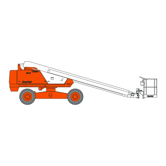
- Page 1 OPERATOR’S MANUAL Part Number 0083739 June 2014 Models TB60/TB60RT Replaces 0083739 March 2014...
- Page 2 The aerial platform is not electrically insulated. Death or serious injury will result from contact with, or inadequate clearance from, an energized conductor. Do not go closer than the minimum safe approach distance as defined by the Minimum Safe Approach Distance section in Chapter 3 – Safety. Regard all conductors as energized.
-
Page 3: Table Of Contents
High Engine Temperature Alarm ......17 Driving and Platform Work Lights ......27 Low Oil Pressure Alarm ........17 Horn Button ............28 Horn ................18 All Motion Alarm............18 Flashing Light ............18 Driving Lights ............18 Platform Work Lights ..........18 Bump Guard System ..........18 TB60 – 0083739... - Page 4 Platform Glazier Package ........40 Lower Controls ............63 Platform Control Cover ...........40 Upper Controls ............63 Placards and Decals..........40 Emergency Lowering ..........64 Prestart Inspection Checklist ........47 Towing ..............65 Chapter 11 – Troubleshooting Troubleshooting Chart ..........67 Appendix A – Glossary Limited Warranty TB60 – 0083739...
-
Page 5: Chapter 1 - Introduction
The aerial platform has been manufactured to conform Additional copies of this manual may be ordered from to all applicable requirement of the following organiza- Snorkel. Supply the model and manual part number tions. from the front cover to assure that the correct manual will be supplied. -
Page 6: Operation
Read and understand sees of ANSI/SIA A92.5-2006 Boom-Supported Elevat- the information in this manual and on the placards ing Work Platforms” is available from Snorkel dealers or and decals on the machine before operating the from the factory upon request. -
Page 7: Chapter 2 - Specifications
LP Fuel Tank Upper Controls Steer Wheels Chassis Right Side Emergency Lowering Hydraulic Fluid Tank Valve And Filter Battery Disconnect Switch Batteries Engine Platform Main Boom Tip Boom Intermediate Boom Platform Steer Wheels Foot Switch Left Side TB60 – 0083739... -
Page 8: Working Envelope
Chapter 2 – Specifications Working Envelope Feet (Meters) (21.3) (18.3) (15.2) (12.2) (9.1) 72° (6.1) 16° (18.3) (15.2) (12.2) (9.1) (6.1) TB60 – 0083739... -
Page 9: General Specifications
Ambient Air Temperature Operating Range High, booms stowed 3.0 mph (4.8 km/h) Fahrenheit 0°F to 110°F Low, booms elevated 1.0 mph (1.6 km/h) Celsius -18°C to 43°C Maximum Wind Speed Gust or steady 28 mph (12.8 m/s) TB60 – 0083739... -
Page 10: Engine Specifications
Note 1: Refer to the engine manufacturers manual for specific fuel recommendations and specifications. Note 2: Refer to the engine manufacturers manual for specific coolant recommendations and specifications. Note 3: Refer to the engine manufacturers manual for specific lubricating oil recommendations and specifications. TB60 – 0083739... - Page 11 Note 3: Refer to the Ford LRG 425 Operator Handbook for specific coolant recommendations and specifications. Note 4: API Starburst symbol on GF-4 oils reads “API Service SM.” Note 5: Refer to the engine manufacturers manual for specific coolant recommendations and specifications. TB60 – 0083739...
-
Page 12: Engine Oil Viscosity
Chapter 2 – Specifications Engine Oil Viscosity Cummins B3.3 Deutz F4L-1011F Deutz F4L-2011F Kubota V2403-M-T SAE 15W/40 TB60 – 0083739... - Page 13 -40 -35 -30 -25 -20 -15 -10 -5 10 15 20 25 30 40 50 °C SAE 5W/30 SAE 0W/30 Note No straight weight oils and no specialized diesel oils are to be used in GM engines. TB60 – 0083739...
- Page 14 Chapter 2 – Specifications TB60 – 0083739...
-
Page 15: Chapter 3 - Safety
Over 350kV to 500kV 7.62 Over 500kV to 750kV 10.67 Over 750kV to 1000kV 13.72 Table 1 – Minimum Safe Approach Distance Denotes prohibited zone Figure 3 – Minimum Safe Approach Distance TB60 – 0083739... -
Page 16: Prestart Inspection
Death or serious injury will result from becoming before transporting, or if it is left unattended. trapped between components, buildings, structures, or other obstacles. Make sure there is sufficient clear- ance around the machine before moving the chassis, TB60 – 0083739... -
Page 17: Tip-Over And Falling Hazards
The hydraulic system contains hoses with hydraulic fluid loads that extend beyond the platform guardrails without under pressure. prior written consent from Snorkel. Danger Do not operate the aerial platform from trucks, trail- Hydraulic fluid escaping under pressure can have ers, railway cars, floating vessels, scaffolds or similar enough force to inject fluid into the flesh. -
Page 18: Engine And Fuel Handling Precautions
Tighten the fuel tank cap securely. If the fuel cap is lost, maintenance and specifications. replace it with an approved cap from Snorkel. Use of a non-approved cap without proper venting may result in Danger pressurization of the tank. -
Page 19: Chapter 4 - Safety Devices
Push the emergency stop button inward to discon- power system. nect power to all control circuits. The length of time the pump can be operated de- Pull the button outward to restore power. pends on the capacity of the battery. TB60 – 0083739... -
Page 20: Emergency Lowering Knob
Figure 4.4 – Platform Do not use the aerial platform for personal fall arrest The foot switch must be engaged and a control must be anchorage. moved to operate the boom, drive and/or platform from the upper controls. TB60 – 0083739... -
Page 21: Ground Fault Circuit Interrupter
An engine temperature gauge is on the lower control panel (refer to Figure 4.7). Do not restart the engine until the condition that caused the low oil pressure has been corrected. TB60 – 0083739... -
Page 22: Horn
If the bump guard comes into contact with a stationary object, the bump guard moves and one or both of the light beams is broken, immediately stopping all platform movement. TB60 – 0083739... -
Page 23: Chapter 5 - Gauges And Displays
Fuel Gauge The fuel gauge is located on top of the diesel or gasoline tank (refer to Figure 5.4). Access the gauge by opening the door on the right side of the chassis. TB60 – 0083739... -
Page 24: Engine Oil
The engine oil level is measured with a dipstick. The dipstick is the only way to accurately determine the engine oil level. The engine oil level should always be between the add and full marks on the dipstick. Figure 5.7 – Hydraulic Fluid Filter Gauge TB60 – 0083739... -
Page 25: Chapter 6 - Controls
The lower controls (refer to Figure 6.2) are located on the An alarm sounds, when the switch is turned on, to warn right side of the turntable. Boom and platform functions others that the machine engine is being started. can be operated from the lower controls. TB60 – 0083739... -
Page 26: Ground Operation Switch
Hold the switch to the right to rotate the turntable speed may be increased by slowly rotating the knob counterclockwise. toward fast. For smooth operation, rotate the knob to slow when ending movement. Hold the switch to the left to rotate the turntable clockwise. TB60 – 0083739... -
Page 27: Platform Level Switch
1. Start the engine from the lower controls. the engine. 2. Place the hydraulic fluid warm-up switch in the on Place the switch in the high position for machine position. operation and for engine and/or hydraulic system warm-up. TB60 – 0083739... -
Page 28: Circuit Breaker Reset Buttons
Turn the switch to start until the engine starts, then The electrical power outlet at the platform has a 15 amp release it to on. circuit breaker. The reset button is on the right side of the electrical box (refer to Figure 6.5). TB60 – 0083739... -
Page 29: Emergency Stop Button
Emergency Stop Button Engine/Emergency Power Switch Throttle Switch Drive Range Switch Boom Joystick Drive Joystick Boom Speed Knob Boom Extension Switch Platform Level Switch Platform Rotation Switch Start Switch Figure 6.6 – Upper Controls TB60 – 0083739... -
Page 30: Boom Joystick
The length of time the • Boom extend/retract pump can be operated depends on the capacity • Boom raise/lower of the battery. Do not use this system for normal • Platform rotate operation. • Platform level up/down TB60 – 0083739... -
Page 31: Platform Foot Switch
Driving and Platform Work Lights The control for the optional driving lights is on the back Figure 6.8 – Upper Control Front of each light. Place the switch in the on position to oper- ate the driving lights. TB60 – 0083739... -
Page 32: Horn Button
Figure 6.9 – Platform Work Lights Horn Button The button for the optional horn is on the right side of the upper control panel (refer to Figure 6.10). Press the button to sound the horn. Horn Button Figure 6.10 – Upper Controls TB60 – 0083739... -
Page 33: Chapter 7 - Prestart Inspection
Lessors and Lessees of ANSI/SIA A92.5-2006 Refer to Chapter 2 for the correct engine oil grade and Boom-Supported Elevating Work Platforms” is in weight. the manual holder. Coolant Cummins, Ford and GM engines are liquid cooled (refer to Figure 7.2). TB60 – 0083739... -
Page 34: Radiator
1. Close the shutoff valve (refer to Figure 7.5). 2. Inspect the fan belt to see that it is in place and not cracked. Radiator To inspect the radiator: 1. Inspect the radiator hoses and clamps for wear, leakage, or damage (refer to Figure 7.2). TB60 – 0083739... -
Page 35: Fuel Line
Cold Weather Start Kit If the machine is equipped with an optional engine block heater, radiator hose in-line heater, visually inspect the heater and power cord. Inspect for leaks around the heater and for damage to the power cord. TB60 – 0083739... -
Page 36: Electrical System
1. Place the aerial platform on a level surface with the 7.7). platform fully stowed. 2. Visually check the battery fluid level making sure the level is within ¼″ (6 mm) of the bottom of the filler neck inside each hole. TB60 – 0083739... -
Page 37: Fluid Filter
1. Inspect all hydraulic hoses, tubes, and fittings for wear, leakage, or damage (refer to Figure 7.9). To inspect foam filled tires and wheels: 1. Check the wheel lug nuts to see that none are miss- ing, damaged, or loose. TB60 – 0083739... -
Page 38: Lower Control Station
1. Use the lower controls to raise the main boom. 4. Let the engine warm to operating temperature. 2. Turn the engine off. 5. Hold the ground operation switch upward. TB60 – 0083739... -
Page 39: Level Sensor
4. Open the rear door on the left side of the machine the start switch on. to access the level sensor (refer to Figure 7.13). 2. Visually check to see that the light is flashing ap- proximately one flash per second. TB60 – 0083739... -
Page 40: Sandblast Protection Kit
3. Look for visible cracks in the weld and at the weld to parent material joint. A bright light may be used to Figure 7.17 – Bottom of Main Boom at Tip End provide adequate visibility of the inspection area. TB60 – 0083739... -
Page 41: Fasteners
To inspect the guardrail system: 1. Inspect all components of the guardrail system. Make sure the rails and toeboards are all in place and free of any damage or deformation. 2. Visually inspect the rail and toeboard welds for cracks. TB60 – 0083739... -
Page 42: Lanyard Anchors
3. At the upper controls (refer to Figure 7.22), pull the Pinch points may exist between moving components. emergency stop button outward and place the start Death or serious injury will result from becoming switch in the on position. trapped between components, buildings, structures, TB60 – 0083739... -
Page 43: Horn
• Turn the engine on and use the switch on the back position to provide electrical power to the two electrical of each light to momentarily turn it on to see that it outlets at the platform. works. TB60 – 0083739... -
Page 44: Tow Kit
Keeper Pins 4. Replace any missing, damaged, or illegible placards or decals before operating the aerial platform. Placard and decal kits are available from Snorkel. Trays The safety related placards and decals are illustrated Figure 7.26 – Platform on the following pages. - Page 45 To prevent machine tip over, replace tires with factory approved foam filled or solid tires ONLY. DO NOT attempt to inflate foam filled or solid tires. 0073298 0073298 SAFE OPERATION INFORMATION IS CONTAINED IN COMPARTMENT LOCATED INSIDE THIS DOOR. 0073491 0073491 TB60 – 0083739...
- Page 46 REACH THROUGH HOLES. 0190989 0074210 0190989 0073298 Right Side 0081441 WARNING EXPLOSION HAZARD DO NOT USE ETHER Engine is equipped with electrical heater starting aid. Use of ether could result in explosion or serious injury. 0075563 0075563 TB60 – 0083739...
- Page 47 0082160 0082160 üüüüüüü DEATH OR SERIOUS INJURY CAN RESULT FROM BEING CRUSHED BETWEEN COUNTERWEIGHT AND TOW VEHICLE. DO NOT ATTEMPT TO ATTACH TOW BAR TO TOW VEHICLE UNLESS SNORKELIFT COUNTERWEIGHT IS TO SIDE OF CHASSIS. 0082203 0082203 TB60 – 0083739...
- Page 48 0074316 (Ford Engine Only Inside Door) 0323899 0323896 0073298 0073298 Left Side T urning battery disconnect switch off while engine is running will damage engine governor. 0074316 0074316 0323896 Front Allow for sway, rock, and sag. 0323899 TB60 – 0083739...
- Page 49 Secure carried material to platform using tie down straps. Protect straps from damage due to sharp edges. Keep area below platform clear of personnel. Do not use in windy conditions. The Snorkel glazier package must only be installed on platforms with side entry gates. 0421078 Radiator...
- Page 50 Chapter 7 – Prestart Inspection TB60 – 0083739...
-
Page 51: Prestart Inspection Checklist
Driving and Platform Work Lights No damage or deformation, proper operation Tow Kit In place, no damage or deformation Platform Glazier Package Good condition Bump Guard System Good condition, proper operation Placards and Decals In place and readable TB60 – 0083739... - Page 52 Chapter 7 – Prestart Inspection TB60 – 0083739...
-
Page 53: Chapter 8 - Operation
3. Place a new can of ether in the cup. than a fast idle until the engine and hydraulic oil has had a chance to warm. The engine may be equipped with 4. Screw the holding cup firmly into position. an optional cold weather start kit. TB60 – 0083739... -
Page 54: Deutz - Manifold Preheater
The engine must be running and the switch used to turn the system on must be at the same location that the en- TB60 – 0083739... -
Page 55: Upper Controls
6. Pull the emergency stop outward (refer to Figure 8.4). 5. Let the engine warm to operating temperature. 6. Hold the ground operation switch upward to the on position while operating the boom and turntable control toggle switches. TB60 – 0083739... -
Page 56: Boom Operation
Death or serious injury can result from improperly driving or steering the aerial platform. Read and understand the information in this manual and on the placards and decals on the machine before op- erating the aerial platform on the job. TB60 – 0083739... -
Page 57: Drive Speeds
• Push the drive joystick to the right to steer to the may not be optimal, which would then allow for loss of right, the direction of the yellow arrow. traction. TB60 – 0083739... -
Page 58: Percent Vs. Degree Of Slope
Drive the aerial platform only on slopes, or loading The grade can be measured with an inclinometer or by 100% Angle of Slope in Degrees 45° 40° Percent of 35° Grade 30° 25° 20° 15° 10° 5° Figure 8.5 – Slope Percent/Degree Conversion TB60 – 0083739... -
Page 59: Machine Gradeability
The machine functions will not operate when the machine/generator selector switch is in the Machine Gradeability generator position. The gradeability specification for four-wheel drive TB60 aerial platforms is 30%. An actual gradeability of 30%, indicates that in most normal working conditions the Caution machine can be driven on a slope with an angle of 16.5... -
Page 60: Dual Fuel
• The maximum working pressure of the line is 250 psi (1,723 kPa). The air line may be used to conduct fluids such as water or antifreeze. Contact Snorkel for compatibility informa- tion before using the air line to conduct other fluids. Caution... -
Page 61: Platform Glazier Package
The glazier package allows the platform operator to eration. position glass at the work place. Refer to the Glazier Package manual (Snorkel Part Number 0421269) for information on proper use of the glazier package. The package includes two lined trays with keeper pins, platform rail padding, and tie-down straps with protectors (refer to Figure 8.11). - Page 62 Chapter 8 – Operation TB60 – 0083739...
-
Page 63: Chapter 9 - Stowing And Transporting
5. Rotate the platform so it is perpendicular to the The aerial platform can tip over if it becomes unsta- boom. ble. Death or serious injury will result from a tip-over accident. Do not drive on slopes that exceed the TB60 – 0083739... -
Page 64: Winching
Hoisting Use a four point sling arrangement attached to the lifting lugs when hoisting the aerial platform. Machine damage can occur if the sling is attached to the booms, turntable, or platform. TB60 – 0083739... -
Page 65: Securing For Transport
Have any damage repaired by a qualified service loose objects from the platform. technician before attempting to hoist the machine. Lifting Lugs (One on each side of machine) Lifting Lugs Front of Machine Rear of Machine Figure 9.4 – Lifting Lugs TB60 – 0083739... - Page 66 14. Use chains or straps to securely fasten the aerial platform to the transport vehicle using the tie-down 9. Close and latch the cowling doors. lugs as attachment points. Proper tie-down and hauling are the responsibility of the carrier. Steel Aluminum Figure 9.6 – Platform TB60 – 0083739...
-
Page 67: Chapter 10 - Emergency Operation
3. Pull the emergency stop button outward. the emergency power system from the upper controls. 4. Place the control selector switch in the lower controls 1. Pull the emergency stop button outward (refer to position. Figure 10.3). 2. Turn the start switch on. TB60 – 0083739... -
Page 68: Emergency Lowering
Danger Pinch points exist between boom components and between the booms and turntable. Death or serious injury will result if the booms or platform lowers onto personnel. Make sure all personnel stand clear while lowering the booms. TB60 – 0083739... -
Page 69: Towing
8. At each drive wheel, remove the two bolts from the disconnect plate (refer to Figure 10.6). Turn the plate over so the nipple points inward. Reinstall the two bolts. TB60 – 0083739... - Page 70 Chapter 10 – Emergency Operation TB60 – 0083739...
-
Page 71: Chapter 11 - Troubleshooting
• If using LPG make certain that the fuel shut-off valve is open. • Try starting the engine for 20 seconds and then let the starter motor cool for 60 seconds. Re- peat as necessary TB60 – 0083739... -
Page 72: Tb60
Push the main system circuit breaker the upper control panel or wiring button back in. If the button pops box has tripped. The engine will not back out, refer the problem to a crank. qualified service technician. TB60 – 0083739... - Page 73 Control selector switch at lower con- Place switch in the upper control trols is in the lower control position. position. Platform foot switch not engaged. Step down on platform foot switch while operating controls. TB60 – 0083739...
- Page 74 Let fluid cool before operating. Hydraulic system component failure. Stow the machine and do not oper- ate until repairs are made. Severe hydraulic leak. Failure of hose, tube, fitting, seal, Do not operate machine until repairs etc. are made. TB60 – 0083739...
- Page 75 Slightly open the bleeder valve and operate the bleeder pump up and down until the air is out of the line. This make take several minutes of operating the pump before the air is removed from the line. Close the valve and start the engine. TB60 – 0083739...
- Page 76 Chapter 11 – Troubleshooting TB60 – 0083739...
-
Page 77: Appendix A - Glossary
This system includes a harness or belt, lanyard prestart inspection – a required safety inspection routine that is performed and a lanyard anchor. Federal OSHA, ANSI and Snorkel require the use daily before operating the aerial platform. - Page 78 Appendix A – Glossary TB60 – 0083739...
- Page 79 5. The Customer and Dealer shall not be entitled to the benefits of this warranty and Snorkel shall have no obligations here under unless the “Predelivery and Inspection Record” has been properly com- pleted and returned to the Snorkel Warranty department within fifteen (15) days after delivery of the Snorkel product to the Customer or Dealer’s demonstration/rental fleet.
-
Page 80: Limited Warranty
Confirmation that a qualified technician is available to replace the part and that this person has been ac- cepted by Snorkel to carry out such work under the warranty of the machine. Failure to do this may nullify the warranty. - Page 81 PURPOSE AND DISCLAIMS ALL LIABILITY FOR INCIDENTAL OR CONSEQUENTIAL DAMAGES, INCLUD- ING BUT NOT LIMITED TO INJURY TO PERSONS OR PROPERTY. The Customer shall make all warranty claims through Snorkel directly or an Authorised Distributor. If unable to contact the Distributor, contact the Snorkel Service Department for further assistance.
-
Page 82: Limited Warranty
Product Warranty APPEAL The buyer may appeal in writing against a rejected or adjusted claim to Snorkel Warranty Department within a period of 21 days of receiving the rejection or adjustment notice. The appeal should be grounded on express rea- sons and supported by relevant evidence. - Page 84 Local Distributor / Lokaler Vertiebshändler / Distributeur local El Distribuidor local / ll Distributore locale EUROPE, MIDDLE EAST AFRICA & ASIA PHONE: +44 (0) 845 1550 058 FAX: +44 (0) 845 1557 756 NORTH & SOUTH AMERICA PHONE: +1 785 989 3000 TOLL FREE: +1 800 255 0317 FAX: +1 785 989 3070 AUSTRALIA...
Need help?
Do you have a question about the TB60 and is the answer not in the manual?
Questions and answers