Table of Contents
Advertisement
Quick Links
Advertisement
Table of Contents

Subscribe to Our Youtube Channel
Related Manuals for BFI Automation CFC 200


Summary of Contents for BFI Automation CFC 200
- Page 1 Original Operating Instructions Compact Flame Controller Type: CFC 200 (formerly 8.x) Document No.: BA CFC200 EN Rev8 BFI Automation Mindermann GmbH Ruegenstrasse 7 42579 Heiligenhaus / Germany Telephone +49 (2056) 98946-0 Facsimile +49 (2056) 98946-42 http://www.bfi-automation.de...
-
Page 3: Table Of Contents
Content General aspects Introduction Warning notes Copyright protection Disposal information Warranty Obligation of the operating company Liability disclaimer Declaration of conformity Address of the manufacturer Safety Intended use Requirements on persons Safety instructions Safety devices 2.4.1 Fundamental aspects 2.4.2 Safety devices on the compact flame controller Safety instructions in case of maintenance and troubleshooting 2.5.1 Fundamental aspects... - Page 4 Content Description Type plate Functional description Optical aperture Operation of the Compact Flame Controller Test of the Compact Flame Controller Care and Maintenance Failures Order data Accessories 10-1...
-
Page 5: General Aspects
General aspects General aspects Introduction These operating instructions are a helpful guide for ensur- ing the successful and safe operation of the compact flame controller. They contain important information on how to operate the controller safely, correctly and effi- ciently. Observing the operating instructions will help to prevent hazards, reduce costs of repair and downtimes and increase the reliability and life of the device. -
Page 6: Warning Notes
General aspects Warning notes The following warning notes are used in these operating instructions: This warning level indicates an imminent hazardous situa- tion. If the hazardous situation is not prevented, this will result in death or severe injury. Follow the instructions that accompany this warning to prevent the risk of death and severe personal injury. -
Page 7: Copyright Protection
These operatint instructions have to be treated as confi- dential. They may only be used by authorised staff. Ac- cess by third parties may only be granted upon written agreement of BFI Automation. All documents are protected in keeping with the German copyright law. -
Page 8: Warranty
• non-performance of specified maintenance work It is recommended that the operator of the device con- cludes a service contract with BFI Automation. This guar- antees that the device is regularly checked by our service staff and ensures that any required wearing and spare... -
Page 9: Obligation Of The Operating Company
General aspects Obligation of the operating company The compact flame controller may cause hazards if it is operated inappropriately or in an improper condition. The operating company is under the obligation to operate the machine in proper state only. The operating company has to secure hazardous areas that exist between BFI de- vices and the customer's own equipment. -
Page 10: Liability Disclaimer
BFI Automation for consequential damages. BFI Automation is liable for possible errors or omissions with the exclusion of additional claims entered into in the framework of the warranty obligations conceded to in the contract. -
Page 11: Declaration Of Conformity
General aspects Declaration of conformity... -
Page 12: Address Of The Manufacturer
General aspects Address of the manufacturer BFI Automation Mindermann GmbH Ruegenstrasse 7 42579 Heiligenhaus Germany Tel. +49 (2056) 98946-0 Fax. +49 (2056) 98946-42 E-mail: info@bfi-automation.de Internet: www.bfi-automation.de... -
Page 13: Safety
Safety Safety Intended use The Compact Flame Controller CFC 200 is intended ex- clusively for the monitoring of flames. The fields of appli- cation of this Compact Flame Controller are flame detec- tions for selective and continuous burner monitoring in in- dustrial steam generators, single and multi-burner fur- naces. -
Page 14: Requirements On Persons
Safety Requirements on persons Work on/with the device may only be performed by per- sons authorized to do so based on their training and quali- fication. Furthermore, such persons have to have been commissioned by the operating company. Do not allow any persons who are being apprenticed, ed- ucated, instructed or on a general training programme to work on the device without the constant supervision of an experienced person. -
Page 15: Safety Instructions
Safety Safety instructions The following instructions on accident prevention have to be observed when operating the compact flame controller. Only operate the device if it is in a proper state ! • Do not remove or disable safety devices. • Check for externally noticeable damage and defects prior to using the device ! Immediately notify the appro- priate authority/person of any changes that occur (in- cluding changes in operating performance). -
Page 16: Safety Devices
Safety Safety devices 2.4.1 Fundamental aspects Check the safety equipment and locking devices on the device for safe operational condition. Only operate the device if all safety devices are present and enabled. The operating company or operator of the compact flame controller is responsible for the proper op- eration of the device. -
Page 17: Safety Instructions In Case Of Maintenance And Troubleshooting
• Operating and auxiliary materials as well as exchanged parts have to be disposed of in a safe and eco-friendly way. • Spare parts supplied by BFI Automation or approved of by BFI Automation only may be used. -
Page 18: Electrical / Electronic Devices
Safety 2.5.2 Electrical / electronic devices Danger to life caused by electrical current! Contact with live wires or components presents a danger to life ! Before working on electrical components, disconnect the compact flame controller from the mains power supply! In keeping with the electrical regulations, work on electri- cal / electronic parts / components may only be carried out by electrical specialists. -
Page 19: Testing In Keeping With The German Workplace Safety Ordinance (Betrsichv)
Safety 2.5.3 Testing in keeping with the German Work- place Safety Ordinance (BetrSichV) In case of the coupling or installation of devices from vari- ous manufacturers or suppliers, the operating company has to carry out a precise test, prior to start-up, in keeping with the German Workplace Safety Ordinance (BetrSichV) in force and the applicable electrical regulations. - Page 20 Safety...
-
Page 21: Technical Data
• Tested by the German Technical Inspection Associa- tion TÜV, approved by DIN DVGW and CSA • For continuous, intermittent and 72-hours operation • CFC 200 UV: For monitoring gas and oil-fired burn- ers in the UV range • CFC 200 UV1:... -
Page 22: Electrical System, Optical And Mechanical Data
Technical data Electrical system, Optical and Mechanical Data spectral sensitivity CFC 200 UV1 (formerly 8.0) 190 bis 550 nm CFC 200 UV (formerly 8.30) 280 bis 420 nm CFC 200 IR (formerly 8.40) 300 bis 1050 nm CFC 200 IR3 (formerly 8.70) 1050 bis 2700 nm Sight view angle 2,7 °... -
Page 23: Weight
Technical data Electrical connection Standard dust-tight Harting plug Ex housing 3m firmly connected special cable Dimensions: Standard with flange 235 x 108 mm ( l x ∅ ) Ex-proof housing 223 x 120 mm ( l x ∅ ) Protection Standard housing IP 65 ATEX Zone 2 Ex-proof housing IP 65... -
Page 24: Setting Elements
Technical data Setting elements 3.5.1 Sensitivity potentiometer The gain of the compact flame controller is adjusted with a potentiometer. The adjustment can be done during op- erating.The sensitivity potentiometer can be found on the back of the housing. To the potentiometer applies: Increase sensitivity by turn- ing clockwise! The potentionmeter can be set in 24 full turns from 0 to 100 % for standard housings and 10 full turns for Ex-proof... -
Page 25: Block Diagram Cfc200
Technical data Block diagram CFC200 0-20mA 4-20mA Electronical shutter LED flame intensity (green) Sensor LED flame relay (yellow) LTD (Long time delay) Monitor channel Preamplifier Window generator Sensitivity potentiometer Relay / safety circuit Band pass filter Relay output High pass filter Galvanic isolation Rectifier Current output... - Page 26 Technical data...
-
Page 27: Transport, Installation And Connection
The legal regulations as well as adjustment instructions of the plant operator have to be observed! Scope of delivery • Compact Flame Controller CFC 200 • Operating instructions • 3 m Connecting cable (with ex-proof housing) • Harting cable terminal box kit (not with ex-proof hous-... -
Page 28: Report Any Damage
Transport, Installation and Connection Report any damage After arrival of the device and accessories, notify the ship- ping agent, the insurance company and BFI Automation immediately in case of any damage caused by transport or inadequate packaging. Take steps to minimise and prevent further damage. -
Page 29: Space Requirement
Transport, Installation and Connection Space requirement See following illustration. Standard housing AutomationAuto- mation tech n olo gy for your future CFC 2000 Type G1” Ser.-No.: 24Vdc Germany G1/2 Explosion-proof housing Ø120 For applications inEx-zone 1... -
Page 30: Installation
Transport, Installation and Connection Installation All installation and connection work may be carried out by qualified and approved specialist staff only ! The legal regulations as well as adjustment instructions of the plant operator have to be observed! Compact Flame Controller Heating insulator Optical alignment device Swivel mount... - Page 31 Transport, Installation and Connection 1 Optical alignment device 3 Heating insulator 2 Compact flame controller 4 Swivel mount The sight tube connection has a G1" internal pipe thread. In order to ensure perfect flame monitoring, the correct and low-vibration position of the sight tube relative to the flame is a significant pre-requisite.
- Page 32 Transport, Installation and Connection Recommendation: For adjustment, use the optical alignment device (availa- ble as an option) as shown in the figure below. The best setting is obtained when a large visual field is achieved. correct incorrect Risk of damage to the eyes from infrared and ultraviolet radiation and from escaping gases during visual flame monitoring! Wear filtering protective goggles !
- Page 33 The entire mechanical peripheral system can be supplied by BFI Automation. Harting plug Sight tube connec- Special cable KW5...
- Page 34 Transport, Installation and Connection For the Ex-housing a special combination is availa- ble.Through the quick release rotation of the fixed con- nection cable is prevented. 1 Special cable KW5 4 Purge air connector 2 Compact flame controller 5 Heating insulator 3 Quick release 6 Swivel mount...
-
Page 35: Works Setting Of The Compact Flame Controller
Transport, Installation and Connection 4.9.1 Works setting of the compact flame controller Danger to life caused by combustion or explosion ! Incorrect installation or adjustment may result in uncon- trolled combustion or explosions! Observe the adjustment instructions of the plant operator! Adjustment work may be carried out only by qualified and approved specialist staff! Compact flame controllers with variable sensitivity set-... -
Page 36: Adaption Of The Compact Flame Controller To The Firing Installation
Transport, Installation and Connection 4.9.2 Adaption of the compact flame controller to the firing installation Danger to life caused by combustion or explosion ! Incorrect installation or adjustment may result in uncon- trolled combustion or explosions! Observe the adjustment instructions of the plant operator! Adjustment work may be carried out only by qualified and approved specialist staff! All adjustments and settings must be carried out, when... -
Page 37: Connection
Transport, Installation and Connection 4.10 Connection 4.10.1 Electrical connection Danger to life caused by electrical current! Electrcal current may lead to injuries or to death! The safety instructions and local safety regulations have to be observed during connection! Have electrical connections made only by authorised spe- cialist personnel! For connection data, please refer to the chapter Technical data and to the following terminal diagram. -
Page 38: Terminal Diagram
Transport, Installation and Connection 4.10.2 Terminal diagram A – Harting device plug (pin contacts) Automa- tionAutoma- tech n olo gy for yo ur future CFC 2000 Type Ser.-No.: 24Vdc Germany B – Harting cable connection box (socket contacts) Connection of standard compact flame controller with special cable KW5 Internal External Con-... -
Page 39: Handling Of Cable Shielding Kw5/Kw6
Transport, Installation and Connection 4.10.3 Handling of cable shielding KW5/KW6 Outer cable shield: The outer cable shield is only on the unit connected through the gland. At the loose end of the cable just cut the outer shield. Inner cable shield: The inner cable shield cut short at both ends. -
Page 40: Laying The Special Cable Kw5/Kw6
Transport, Installation and Connection 4.10.4 Laying the special cable KW5/KW6 inner PUR Contact- Crimp contact Plastic insert insert jacket outer PUR thread union nut jacket single core outer shielding It must not remain unequipped contact chambers. All con- tact chambers have to be equipped with crimp contacts. The outer shield is connected to the compact flame con- troller side in a large area by a clamping connection be- tween the plastic liner and the threaded portion of the... -
Page 41: Storage
Transport, Installation and Connection 4.11 Storage Do not unpack the packed compact flame controller and accessories. The following conditions apply to storage: • Store in a dry place. Maximum relative humidity 60%. Ensure that the packages are not stored outdoors. In addition, It has to be assured that the floor in the storage area will remain dry throughout the storage pe- riod. - Page 42 Transport, Installation and Connection 4-16...
-
Page 43: Description
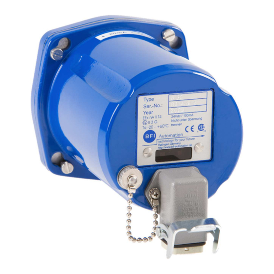
Description Description Type plate The type plate is located on the back of the device hous- ing and contains the device type designation and the se- rial number. Functional description For flame radiation analysis the compact flame controller is using the integral method in the respective spectral range. -
Page 44: Optical Aperture
Description Optical aperture For the compact flame controllers CFC 200 IR and CFC 200 IR3 radiation to the sensor element (3) can be re- duced with an optical aperture. When the smallest hole is positioned in front of the sensor element, the lowest inci- dence of radiation is done on the element. -
Page 45: Operation Of The Compact Flame Controller
Operation of the Compact Flame Controller Operation of the Compact Flame Controller Danger of injury and material damage if improperly used! Improper use of the compact flame controller can lead to injury or even death and to material damage! Operation of the compact flame controller only by author- ised and qualified special personnel! Observe the operating instructions! The response of the compact flame controller depends on... - Page 46 Operation of the Compact Flame Controller...
-
Page 47: Care And Maintenance
Care and Maintenance Care and Maintenance The compact flame controller is maintenance-free. For cleaning, use a moist cloth to wipe the housing from the outside only and clean the lens in regular intervals. Take care not to scratch the lens! - Page 48 Care and Maintenance...
-
Page 49: Failures
Failures Failures Problem: Display: Cause: Remedy: No Flame No mA output signal Compact flame Check voltage supply controller not ON signal Yellow LED OFF Replace compact flame control- after the functioning Green LED OFF burner Check electrical connection No data communica- tion started Flame signal (soft-... - Page 50 Failures...
-
Page 51: Order Data
CFC 200 UV 6012-2031-00 CFC 200 IR 6012-2041-00 CFC 200 IR3 6012-2081-00 Compact flame controller with Ex housing Zone 1 Order-No. CFC 200 UV1 EX 7012-2002-00 CFC 200 UV EX 7012-2032-00 CFC 200 IR EX 7012-2042-00 CFC 200 IR3EX 7012-2082-00... - Page 52 Order data...
-
Page 53: Accessories
Accessories Accessories Accessories Order-No. Power supply 5002 ( 230 V AC - 6020-5002-00 > 24 V DC ) Power supply 5002 ( 115 V AC - 6020-5002-01 > 24 V DC ) Swivel mount 1“ with 2“ flange 6590-9020-01 plate, passivated steel 3-Way- ball valve 1“... - Page 54 Accessories 10-2...
- Page 55 Accessories 10-3...
- Page 56 Accessories BFI Automation 2018 10-4...
Need help?
Do you have a question about the CFC 200 and is the answer not in the manual?
Questions and answers