Advertisement
COMPACT FLAME CONTROLLER
CFC 200
(Formerly 8.XX)
TECHNICAL DESCRIPTION
EDITION: TB CFC200-REV3-2015-04-07
Please note, that all mounting and wiring as well as all changing or adjustment at
IMPORTANT:
the flame monitoring and evaluation equipment should only be carried out by fully
trained and authorized personnel.
BFI Automation is pleased to support you if you do not have any experience with
the equipment. Our service personnel is carrying out world wide installations, su-
pervision and commissioning and is available upon request.
For the stage of planning you can ask our sales and project engineers for any
support you may need.
BFI Automation is providing any kind of training for your engineers.
PLEASE READ THIS LEAFLET CREFULLY AS IT CONTAINS NECESSARYIN-
FORMATION FOR THE USE OF THIS EQUIPMENT. FOR MORE DETAILED IN-
FORMATION PLEASE REFER TO THE OPERATING AND MAINTENANCE MA-
NUAL.
BFI – Automation Mindermann GmbH, Eggerscheidter Str. 57, D-40883 Ratingen
Phone +49 (0) 2102 96 82 – 0, Fax +49 (0) 2102 9682 – 42
:
EMail
info@bfi-automation.de
1
Advertisement
Table of Contents

Subscribe to Our Youtube Channel
Related Manuals for BFI Automation CFC 200


Summary of Contents for BFI Automation CFC 200
- Page 1 BFI Automation is pleased to support you if you do not have any experience with the equipment. Our service personnel is carrying out world wide installations, su- pervision and commissioning and is available upon request.
- Page 2 Flame scanner with integrated flame controller TÜV approved, DIN-DVGW certified CFC 200 UV1 (formerly 8.0) : recommended for pure gas and oil/gas mixture fuels CFC 200 UV (formerly 8.30) : recommended for pure gas and oil/gas mixture fuels CFC 200 IR (formerly 8.40) : recommended for pure oil fuels in diffusion burners CFC 200 IR3 (formerly 8.70): recommended for gas fuels in radiant-surface burners...
-
Page 3: Sensitivity Adjustment
Sensitivity Adjustment By using a potentiometer which is located on the back side of the compact flame controller beneath a screw it is easily possible to adapt the controller to various firing conditions. Turning the potentiometer counter clockwise will reduce the sensitivity. Please note that a reduction of the sensitivity might also cause a reduction of the current output for the intensity. - Page 4 flame root combustion area primary air fuel changing of frequency and amplitude in relationship to the distance of the flame root ball flange how to adjust in the right way sight tube mounting flange flame scanner adjustment angle 30° max optical heating adjustment...
-
Page 5: Installation
Installation The pin configuration of the plug connector is shown in the terminal connection diagram. The flame intensity output has no potential separation from the power supply. It is related to the power supply ground. If there will be any problem in this case an isolation amplifier can be delivered on de- mand. -
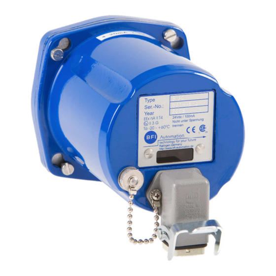
Page 6: Standard Housing
Standard housing Standard housing suitable for use in hazardous area Zone 2 II 3 G Ex nA II T4 OE-Converter housing Fibre optic cable O/E-Converter Suitable for use in hazardous areas Zone 2 II 3 G Ex nA II T4... - Page 7 Ex-proofed housing 2 8 6 LED grün = Intensität Empfindlichkeits- LED gelb = Flamme "EIN" einstellung For areas classified as Zone I PTB 03 ATEX 1051 0044 Type 07-6152-9016 II 2G Ex de IIC T6 II 2D Ex tD A22 IP 65 T 80°C Explosion Proof Housing for OE-Converter For one OE-Converter Ø13...
-
Page 8: Technical Data
3-way ball cock 1 inch Pressure screw joint 5bar size 1 inch Optical adjusting device Technical data Spectral sensitivity CFC 200 UV1 (formerly 8.0) 190 up to 550 nm CFC 200 UV (formerly 8.30) 280 up to 420 nm CFC 200 IR (formerly 8.40) 300 up to 1050 nm CFC 200 IR3 (formerly 8.70) - Page 9 13.0 kg Electronic self-monitoring for the fail-safe function control of the device according VDE 0116, EN 298:2012, and TRD 411 to 414. DIN-DVGW approved and CE conformity. Certified to CSA standards. Rights for technical changes reserved © BFI AUTOMATION 2015...
Need help?
Do you have a question about the CFC 200 and is the answer not in the manual?
Questions and answers