Table of Contents
Advertisement
Quick Links
Original Operating Instructions
Original Operating Instructions
Original Operating Instructions
Compact Flame Controller
Compact Flame Controller
Type:
Type:
Document-No.:
Document
Document-No.:
Document
Eggerscheidter Strasse 57
D-40883 Ratingen / Germany
Telephone +49 (2102) 9682-0 Facsimile +49 (2102) 9682
Telephone +49 (2102) 9682
http://www.bfi-automation.de
CFC 4000L
BA CFC4000L EN Rev.
Software settings
HB CFC Com1 EN
BFI Automation
Mindermann GmbH
Facsimile +49 (2102) 9682-42
EN Rev.1
see
Advertisement
Table of Contents

Subscribe to Our Youtube Channel
Related Manuals for BFI Automation CFC 4000L


Summary of Contents for BFI Automation CFC 4000L
- Page 1 Original Operating Instructions Original Operating Instructions Original Operating Instructions Compact Flame Controller Compact Flame Controller Type: Type: CFC 4000L Document Document-No.: BA CFC4000L EN Rev. EN Rev.1 Software settings Document Document-No.: HB CFC Com1 EN BFI Automation Mindermann GmbH Eggerscheidter Strasse 57...
-
Page 3: Table Of Contents
Content General aspects Introduction Warning notes Copyright protection Disposal information Warranty Obligation of the operating company Liability disclaimer Declaration of conformity Address of the manufacturer Safety Intended use Requirements on persons Safety instructions Safety devices 2.4.1 Fundamental aspects 2.4.2 Safety devices on the compact flame controller Safety instructions in case of maintenance and troubleshooting 2.5.1 Fundamental aspects... - Page 4 Content Description Type plate Functional description Hardware settings 5.3.1 The frequency filter 5.3.2 Safety switch-OFF time of the safety channel Operation of converter 6012 5.4.1 Image of a BUS system Operation of the Compact Flame Controller Test of the Compact Flame Controller Care and Maintenance Failures Order data...
-
Page 5: General Aspects
General aspects General aspects Introduction These operating instructions are a helpful guide for ensur- ing the successful and safe operation of the compact flame controller. They contain important information on how to operate the controller safely, correctly and effi- ciently. Observing the operating instructions will help to prevent hazards, reduce costs of repair and downtimes and increase the reliability and life of the device. -
Page 6: Warning Notes
General aspects Warning notes The following warning notes are used in these operating instructions: This warning level indicates an imminent hazardous situa- tion. If the hazardous situation is not prevented, this will result in death or severe injury. Follow the instructions that accompany this warning to prevent the risk of death and severe personal injury. -
Page 7: Copyright Protection
These operatint instructions have to be treated as confi- dential. They may only be used by authorised staff. Ac- cess by third parties may only be granted upon written agreement of BFI Automation. All documents are protected in keeping with the German copyright law. -
Page 8: Warranty
• non-performance of specified maintenance work It is recommended that the operator of the device con- cludes a service contract with BFI Automation. This guar- antees that the device is regularly checked by our service staff and ensures that any required wearing and spare... -
Page 9: Obligation Of The Operating Company
General aspects Obligation of the operating company The compact flame controller may cause hazards if it is operated inappropriately or in an improper condition. The operating company is under the obligation to operate the machine in proper state only. The operating company has to secure hazardous areas that exist between BFI devices and the customer's own equipment. -
Page 10: Liability Disclaimer
BFI Automation for consequential damages. BFI Automation is liable for possible errors or omissions with the exclusion of additional claims entered into in the framework of the warranty obligations conceded to in the contract. -
Page 11: Declaration Of Conformity
ATEX 95 Directive 94/9/EC EMC Directive 2004/108/EC This Declaration of Conformity is the result of an examina- tion by BFI Automation in accordance with the European regulations. Any modification to the system not approved by us will in- validate this declaration. -
Page 12: Address Of The Manufacturer
General aspects Address of the manufacturer BFI Automation Mindermann GmbH Eggerscheidter Strasse 57 D-40883 Ratingen Germany Tel. +49 (2102) 9682-0 Fax. +49 (2102) 9682-42 E-mail: info@bfi-automation.de Internet: www.bfi-automation.de... -
Page 13: Safety
Compact Flame Controller are flame de- tections for selective and continuous burner monitoring in industrial steam generators, single and multi-burner fur- naces. The CFC 4000L may only be operated with fibre optic cables that were supplied by BFI Automation. Danger when improperly used ! The device may cause hazards if it is not used as in- tended and/or for any other purposes. -
Page 14: Requirements On Persons
Safety Requirements on persons Work on/with the device may only be performed by per- sons authorized to do so based on their training and quali- fication. Furthermore, such persons have to have been commissioned by the operating company. Do not allow any persons who are being apprenticed, educated, instructed or on a general training programme to work on the device without the constant supervision of an experienced person. -
Page 15: Safety Instructions
Safety Safety instructions The following instructions on accident prevention have to be observed when operating the compact flame controller. Only operate the device if it is in a proper state ! • Do not remove or disable safety devices. • Check for externally noticeable damage and defects prior to using the device ! Immediately notify the ap- propriate authority/person of any changes that occur (including changes in operating performance). -
Page 16: Safety Devices
Safety Safety devices 2.4.1 Fundamental aspects Check the safety equipment and locking devices on the device for safe operational condition. Only operate the device if all safety devices are present and enabled. The operating company or operator of the compact flame controller is responsible for the proper op- eration of the device. -
Page 17: Safety Instructions In Case Of Maintenance And Troubleshooting
• Operating and auxiliary materials as well as exchanged parts have to be disposed of in a safe and eco-friendly way. • Spare parts supplied by BFI Automation or approved of by BFI Automation only may be used. -
Page 18: Electrical / Electronic Devices
Safety 2.5.2 Electrical / electronic devices Danger to life caused by electrical current! Contact with live wires or components presents a danger to life ! Before working on electrical components, disconnect the compact flame controller from the mains power supply! In keeping with the electrical regulations, work on electri- cal / electronic parts / components may only be carried out by electrical specialists. -
Page 19: Technical Data
Technical data Technical data General characteristic features • Flame scanner with integrated amplifier and flame re- • Tested by the German Technical Inspection Associa- tion TÜV, approved by DIN DVGW • For continuous, intermittent and 72-hours operation • Type UV, UV1: For monitoring gas and oil-fired burn- ers in the UV range •... -
Page 20: Electrical System, Optical And Mechanical Data
Technical data 3.2 Electrical system, Optical and Mechanical Data Spectral sensitivity 280 to 420 nm 190 to 550 nm 300 to 1050 nm 300 to 2700 nm Angle of view 3° with SKL Self-monitoring Fully electronic, 1 x per 800 ms Operating voltage 24 V DC Current consumption... - Page 21 Technical data Fibre optic connection M30 outer thread, metric Electrical connection Standard housing dust-tight Harting plug Ex-proof housing terminal compartment in housing Housing dimension Standard housing* 122 x 120 x 80 mm Ex-proof housing for 1 device* 232 x 232 x 166.5 mm for 2 or 3 devices* 276 x 276 x 218 mm *without connector and...
-
Page 22: Weight
Technical data Weight 2.0 L 2.0 LEX 2.0 LEX2/3 1.5 kg 7.0 kg 13.0 kg Dimensions 2.0 L 2.0 LEX 2.0 LEX2/3 L 125 mm L 356 mm L 400 mm W 160 mm W 232 mm W 276 mm H 90 mm H 165 mm H 218 mm... -
Page 23: Block Diagram Cfc4000
Technical data Block diagram CFC4000 Sensor Data output RS232 Pre-amplifier Flame relay Band-pass filter Monitor relay DC voltage part Relay contact with fuse F3 Frequency part Data input RS232 Modulation part J1-3 Monitor channel switch-off time Monitor channel Frequency tap selection Switchover to channel 2 (external) µP Microprocessor... - Page 24 Technical data...
-
Page 25: Transport, Installation And Connection
The legal regulations as well as adjustment instructions of the plant operator have to be observed! Scope of delivery • Compact Flame Controller CFC 4000L • Operating instruction BA CFC 4000L EN • Harting cable terminal box kit (not with ex-proof hous- ing) Accessories (optional) •... -
Page 26: Packaging
Transport, Installation and Connection Report any damage After arrival of the device and accessories, notify the shipping agent, the insurance company and BFI Auto- mation immediately in case of any damage caused by transport or inadequate packaging. Take steps to minimise and prevent further damage. Report the insurance case to the insurance company without delay and transmit the full claim documents at once in order to expedite the claims settlement (at the... -
Page 27: Space Requirement
Transport, Installation and Connection Space requirement See following illustration. Standard housing... - Page 28 Transport, Installation and Connection Ex-proof housing for 1 OE-Converter Ø13 For applications in Ex-area Zone 1...
-
Page 29: Installation
Transport, Installation and Connection Installation All installation and connection work may be carried out by qualified and approved specialist staff only ! The legal regulations as well as adjustment instructions of the plant operator have to be observed! Optical alignment device Union nut SW55 Fibre optic cable Adapter flange... - Page 30 Transport, Installation and Connection Transport, Installation and Connection Recommendation: For adjustment, use the optical adjustment aid (available For adjustment, use the optical adjustment aid (available as an option) as shown in the figure below. The best se as an option) as shown in the figure below. The best set- ting is obtained when a large visual field is achieved.
- Page 31 The entire mechanical peripheral system can be sup- plied by BFI Automation. OE-Converter 5 3-Way valve Fibre optic cable 6 Double nipple...
-
Page 32: Works Setting Of The Compact Flame Controller
Transport, Installation and Connection 4.7.1 Works setting of the compact flame control- Danger to life caused by combustion or explosion ! Incorrect installation or adjustment may result in uncon- trolled combustion or explosions! Observe the adjustment instructions of the plant opera- tor! Adjustment work may be carried out only by qualified and approved specialist staff! -
Page 33: Adaption Of The Compact Flame Controller To The Firing Installation
Transport, Installation and Connection 4.7.2 Adaption of the compact flame controller to the firing installation Danger to life caused by combustion or explosion ! Incorrect installation or adjustment may result in uncon- trolled combustion or explosions! Observe the adjustment instructions of the plant opera- tor! Adjustment work may be carried out only by qualified and approved specialist staff! -
Page 34: Connection
Transport, Installation and Connection Connection 4.8.1 Electrical connection Danger to life caused by electrical current! Electrcal current may lead to injuries or to death! The safety instructions and local safety regulations have to be observed during connection! Have electrical connections made only by authorised specialist personnel! For connection data, please refer to the chapter Techni- cal data and to the following terminal diagram. -
Page 35: 4.8.2 Terminal Diagram
Transport, Installation and Connection 4.8.2 Terminal diagram A – Harting device plug (pin contacts) B – Harting cable connection box (socket contacts) Connection of standard compact flame controller Internal External Con- Conduc- Function Burner Power supply tact tor colour control display Flame relay lead Flame relay Flame ON... - Page 36 Transport, Installation and Connection Pin/Terminal Description colour BFI Special cable KW6 Flame relay: Root white Flame relay ‘Flame ON’ brown Data input (write) pink Power supply +24 V DC green Power supply 0V (GND) yellow Current output 0(4)-20 mA gray Sensitivity switchover channel 2 blue RS232output (read only)
-
Page 37: Laying The Special Cable Kw6 For Standard Housing
Transport, Installation and Connection 4.8.3 Laying the special cable KW6 for standard housing Contact- inner PUR Crimp contact Plastic insert insert jacket outer PUR thread union nut jacket single core outer shielding No contact chamber may remain bare ! All contact chambers in the contact insert have to be fit- ted with crimp contacts ! For this purpose use a suitable crimp tool (BFI part No. -
Page 38: Laying The Special Cable Kw6 For Ex-Proof Housings
Transport, Installation and Connection 4.8.4 Laying the special cable KW6 for Ex-proof housings The outer braided shield shall be clamped between clamp collar I & II on the scanner side. Assembly: First the cable and the clamp collars must be fixed with screwed cap I. -
Page 39: Storage
Transport, Installation and Connection Storage Do not unpack the packed compact flame controller and accessories. The following conditions apply to storage: • Store in a dry place. Maximum relative humidity 60%. Ensure that the packages are not stored outdoors. In addition, It has to be assured that the floor in the storage area will remain dry throughout the storage period. - Page 40 Transport, Installation and Connection 4-16...
-
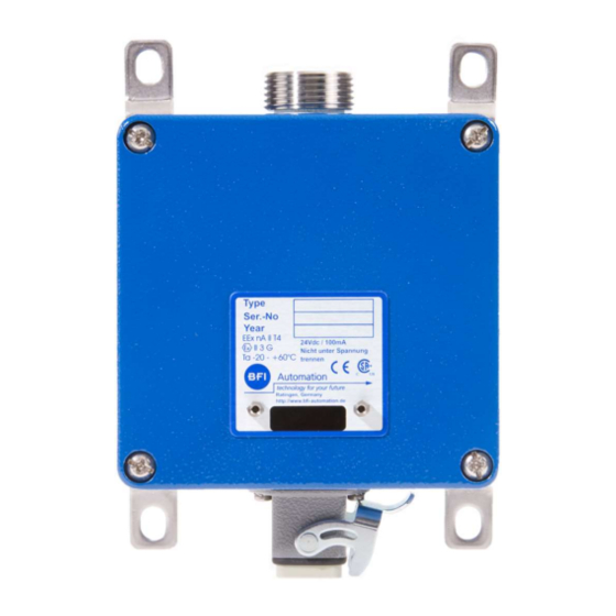
Page 41: Description
Description Description Type plate The type plate is located on the device housing and co plate is located on the device housing and con- tains the device type designation and the serial number. he device type designation and the serial number. Functional description For flame radiation analysis the compact flame controller For flame radiation analysis the compact flame controller... -
Page 42: Hardware Settings
Settings can only be changed on the printed circuit board. 5.3.1 The frequency filter The CFC 4000L has a four-step frequency filter in the sig- nal input. The evaluation of the flame signal by the soft- ware takes place only downstream of the frequency filter. -
Page 43: Safety Switch-Off Time Of The Safety Channel
Description 5.3.2 Safety switch-OFF time of the safety channel The safety switch-OFF time of the safety channel (hard- ware) is set by means of a jumper. The settings are as fol- lows: Jumper 1 bridged: 1 second Jumper 2 bridged: 3 seconds Jumper 3 bridged: 5 seconds If a switch-OFF time of 2 seconds is required, the jumper must be inserted in position 2 (3 seconds) and the switch-... -
Page 44: Operation Of Converter 6012
Description Operation of converter 6012 The converter box 6012 is specially designed and adapted for the connection of the compact flame control- ler type CFC 4000. This converter box will expand the va- riety of functions of the CFC series and to use them in the maximum range. -
Page 45: Image Of A Bus System
Description 5.4.1 Image of a BUS system... - Page 46 Description...
-
Page 47: Operation Of The Compact Flame Controller
Operation of the Compact Flame Controller Operation of the Compact Flame Controller Danger of injury and material damage if improperly used! Improper use of the compact flame controller can lead to injury or even death and to material damage! Operation of the compact flame controller only by author- ised and qualified special personnel! Observe the operating instructions! The response of the compact flame controller depends on... - Page 48 Operation of the Compact Flame Controller...
-
Page 49: Care And Maintenance
Care and Maintenance Care and Maintenance The compact flame controller is maintenance-free. For cleaning, use a moist cloth to wipe the housing from the outside only. When storing the compact flame controller, make sure the fiber optic connector socket cover with suitable cap! Maintenance for SIL applications according to SIL-Safety Handbook SIL-HB_CFCx000. - Page 50 Care and Maintenance...
-
Page 51: Failures
Failures Failures Problem: Display: Cause: Remedy: No Flame No mA output signal Compact flame Check voltage supply ON signal controller not Yellow LED OFF Replace compact flame control- after the functioning Green LED OFF burner Check electrical connection No data communica- tion started Flame signal (soft-... - Page 52 Failures...
-
Page 53: Order Data
Order data Order data The compact flame controller is available from BFI Auto- mation GmbH under the following order data: Compact flame controller with standardhousing Zone 2 Order-No. OE-Converter CFC 4000 UV S 522.3L OE-Converter CFC 4000 UV1 S 522.0L OE-Converter CFC 4000 IR S 522.4L OE-Converter CFC 4000 IR2... - Page 54 Order data 3 x Compact flame controller for Ex-housing Zone 1 GUB03 Order-No. 3 x OE-Converter CFC 4000 UV LEX S 522.3LEXG3 3 x OE-Converter CFC 4000 UV1 LEX S 522.0LEXG3 3 x OE-Converter CFC 4000 IR LEX S 522.4LEXG3 3 x OE-Converter CFC 4000 IR2 LEX S 522.6LEXG3...
-
Page 55: Accessories
Accessories Accessories Communication and Software Order-No. Communication set (CFC Com1, 6040-4901-00 CFC-NET and IR/USB-interface cable, 1.5 m) IR/USB-interface cable without 6040-4810-10 software, 1.5 m IR/USB-interface cable without 6040-4810-13 software, 3 m Additional accessories Order-No. Converter 6012 G 677 Converter 6012 integrated in a G 677.1 wall mounting housing IP66 Special cable KW6, yard ware... - Page 56 Accessories © BFI Automation 2016 10-2...
Need help?
Do you have a question about the CFC 4000L and is the answer not in the manual?
Questions and answers