Grizzly G0623X Owner's Manual
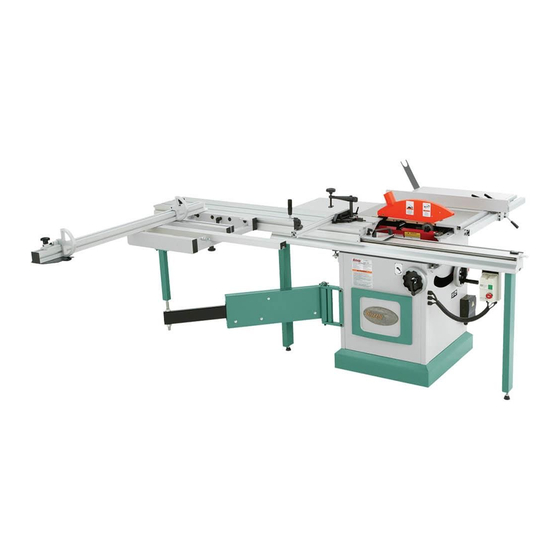
10" sliding table saw
Hide thumbs
Also See for G0623X:
- Owner's manual (96 pages) ,
- Machine data sheet (3 pages) ,
- Parts list (16 pages)
Table of Contents
Advertisement
Quick Links
MODEL G0623X/G0623X3
10" SLIDING TABLE SAW
OWNER'S MANUAL
(For models manufactured since 05/22)
G0623X ONLY
COPYRIGHT © NOVEMBER, 2007 BY GRIZZLY INDUSTRIAL, INC., REVISED JULY, 2022 (KS)
WARNING: NO PORTION OF THIS MANUAL MAY BE REPRODUCED IN ANY SHAPE
OR FORM WITHOUT THE WRITTEN APPROVAL OF GRIZZLY INDUSTRIAL, INC.
#TR9147 PRINTED IN TAIWAN
V6.07.22
***Keep for Future Reference***
Advertisement
Chapters
Table of Contents

Related Manuals for Grizzly G0623X


Summary of Contents for Grizzly G0623X
- Page 1 (For models manufactured since 05/22) G0623X ONLY COPYRIGHT © NOVEMBER, 2007 BY GRIZZLY INDUSTRIAL, INC., REVISED JULY, 2022 (KS) WARNING: NO PORTION OF THIS MANUAL MAY BE REPRODUCED IN ANY SHAPE OR FORM WITHOUT THE WRITTEN APPROVAL OF GRIZZLY INDUSTRIAL, INC.
- Page 2 This manual provides critical safety instructions on the proper setup, operation, maintenance, and service of this machine/tool. Save this document, refer to it often, and use it to instruct other operators. Failure to read, understand and follow the instructions in this manual may result in fire or serious personal injury—including amputation, electrocution, or death.
-
Page 3: Table Of Contents
Needed for Setup ......... 17 Unpacking ............ 17 Wiring Safety Instructions ......76 Inventory ............18 G0623X Wiring Diagram ......77 Hardware Recognition Chart ....... 20 G0623X3 7.5 HP 220V Wiring Diagram ..78 Cleanup ............21 G0623X3 7.5 HP 440V Wiring Diagram ..79 Site Considerations ........ -
Page 4: Introduction
Always consider safety first, as it applies to your individual working conditions. Use this and other machinery with caution and respect. Failure to do so could result in serious personal injury, damage to equip- ment, or poor work results. Model G0623X/G0623X3 (Mfd. Since 05/22) -
Page 5: Identification
H. Blade Angle Handwheel: Adjusts angle of saw blades. E. Blade Guard: Fully-adjustable blade guard maintains maximum protection around saw Blade Elevation Handwheel: Adjusts height blade, and a 2½" dust port effectively extracts of main saw blade. dust from cutting operation. Model G0623X/G0623X3 (Mfd. Since 05/22) - Page 6 5 HP 7.5 HP Voltage 230V 220V/440V Prewired Not Applicable 220V Phase Single-Phase 3-Phase Amps 18A @ 220V, 9A @ 440V Speed 3450 RPM Centrifugal Switch/Contacts External Power Transfer V-Belt Drive Bearings Sealed and Lubricated Model G0623X/G0623X3 (Mfd. Since 05/22)
- Page 7 1/2 in. Sliding Table T-Slot Bottom Width 1-1/4 in. Fence Information Fence Type Single Lever Locking, Extruded Aluminum Fence Size Length 33-1/2 in. Fence Size Width 2 in. Fence Size Height 4-1/4 in. Fence Stops Model G0623X/G0623X3 (Mfd. Since 05/22)
- Page 8 Other Related Information No of Dust Ports Dust Port Size 4, 2-1/2 in. Other Specifications Country of Origin Taiwan Warranty 1 Year Approximate Setup Time 1-1/2 Hours Serial Number Location ID Label ISO 9001 Factory Model G0623X/G0623X3 (Mfd. Since 05/22)
- Page 9 Customer Service #: (570) 546-9663 • To Order Call: (800) 523-4777 • Fax #: (800) 438-5901 Customer Service #: (570) 546-9663 • To Order Call: (800) 523-4777 • Fax #: (800) 438-5901 MODEL G0623X 10" SLIDING TABLE SAW model g0623X3 10" SlIdINg TABle SAW MODEL G0623X/G0623X3 10"...
-
Page 10: Section 1: Safety
Never operate under the influence of drugs or injury or blindness from flying particles. Everyday alcohol, when tired, or when distracted. eyeglasses are NOT approved safety glasses. Model G0623X/G0623X3 (Mfd. Since 05/22) - Page 11 EXPERIENCING DIFFICULTIES. If at any time debris. Make sure they are properly installed, you experience difficulties performing the intend- undamaged, and working correctly BEFORE ed operation, stop using the machine! Contact our operating machine. Technical Support at (570) 546-9663. Model G0623X/G0623X3 (Mfd. Since 05/22)
-
Page 12: Additional Safety For Sliding Table Saws
Cutting operation “freehand”. Turn OFF saw and wait metal, glass, stone, tile, etc. increases risk of until blade is completely stopped before removing operator injury due to kickback or flying particles. workpiece. -10- Model G0623X/G0623X3 (Mfd. Since 05/22) -
Page 13: Preventing Kickback
Promptly fix the condition that prevented you from completing the cut, before starting the saw again. -11- Model G0623X/G0623X3 (Mfd. Since 05/22) -
Page 14: Glossary Of Terms
Through Cut: A cut in which the blade cuts com- Non-Through Cut: A cut in which the blade does pletely through the workpiece (refer to Page 37). not cut through the top of the workpiece. Refer to Page 37 for more details. -12- Model G0623X/G0623X3 (Mfd. Since 05/22) -
Page 15: Section 2: Power Supply
G0623X at 230V, 1-Ph ......19 Amps path of least resistance for electric current. G0623X3 at 220V, 3-Ph ....... 18 Amps G0623X3 at 440V, 3-Ph ...... - Page 16 -14- Model G0623X/G0623X3 (Mfd. Since 05/22)
- Page 17 (isolated) from the power G0623X ....3 Wire, 10 AWG, 50 ft. or less supply when required. This installation must be G0623X3 (220V) 4 Wire, 10 AWG, 50 ft. or less performed by an electrician in accordance with all G0623X3 (440V) .......N/A (Hardwired)
-
Page 18: G0623X3 440V Voltage Conversion
Rewire motor to 440V as shown in diagram can be accessed easier for rewiring if the blade is on Page 80. moved to 0˚ (90˚ to table) before beginning. Replace junction box cover, cabinet door cover, and magnetic switch cover. -16- Model G0623X/G0623X3 (Mfd. Since 05/22) -
Page 19: Section 3: Setup
IMPORTANT: Save all packaging materials until you are completely satisfied with the machine and have resolved any issues between Grizzly or the shipping agent. You MUST have the original pack- aging to file a freight claim. It is also extremely helpful if you need to return your machine later. -
Page 20: Inventory
H. Crosscut Table Support Leg ....... 1 Flip Stops ........... 2 Lock Lever M12-1.75 x 55 ......1 K. Flat Washer 12mm ........1 L. T-Nut M12-1.75 ..........1 Figure 4. Table saw. Figure 6. Crosscut table items. -18- Model G0623X/G0623X3 (Mfd. Since 05/22) - Page 21 X. Fixed Table End Cover ....... 1 Combo Wrench 17mm (Not Shown) ... 1 Z. Closed-End Wrench 19/22mm (Not Shown) . 1 AA. Arbor Wrench (Not Shown) ......1 Figure 10. Sliding table items. Figure 8. Miscellaneous components. -19- Model G0623X/G0623X3 (Mfd. Since 05/22)
- Page 22 AT. Hose Clamps 2 ⁄ " ........2 (ST Handle) ............2 Lock Washers 6mm (ST Handle) ...... 2 Flat Washers 6mm (ST Handle) ......4 Hex Nuts M6-1 (ST Handle) ......2 Figure 11. Miscellaneous components. -20- Model G0623X/G0623X3 (Mfd. Since 05/22)
-
Page 23: Hardware Recognition Chart
Hardware Recognition Chart USE THIS CHART TO MATCH UP HARDWARE DURING THE INVENTORY AND ASSEMBLY PROCESS. Flat Head Screw -21- Model G0623X/G0623X3 (Mfd. Since 05/22) -
Page 24: Cleanup
Figure 12. T23692 Orange Power Degreaser. Repeat Steps 2–3 as necessary until clean, then coat all unpainted surfaces with a quality metal protectant to prevent rust. -22- Model G0623X/G0623X3 (Mfd. Since 05/22) -
Page 25: Site Considerations
Only install in an Shadows, glare, or strobe effects that may distract access restricted location. or impede the operator must be eliminated. 123" 76" 150" Figure 13. Minimum working clearances. -23- Model G0623X/G0623X3 (Mfd. Since 05/22) -
Page 26: Lifting & Placing
We strongly recommend securing your machine to the floor if it is hardwired to the power source. Consult with your electrician to ensure compliance with local codes. Figure 14. Lifting the table saw cabinet. -24- Model G0623X/G0623X3 (Mfd. Since 05/22) -
Page 27: Assembly
Figure 18, to act as leveling set screws in a later step. Mounting Cap Screws T-Stud Inserted Through Mounting Bracket Figure 16. T-stud inserted in mounting bracket. Leveling Set Screws Figure 18. Large extension table installed. -25- Model G0623X/G0623X3 (Mfd. Since 05/22) -
Page 28: Cast Iron Table
Spacing Table Hex Nut Flat Washer Scale Hex Bolt Lock Washer Figure 22. Fence base installed; spacing Figure 20. Mounting rip fence scale. between fence base and scale bar. -26- Model G0623X/G0623X3 (Mfd. Since 05/22) - Page 29 6mm flat washers (see Figure 26). Rip Fence Attachment Location T-Bar Support Leg Extension Lock Levers Figure 24. Rip fence installed on fence base. Figure 26. Support leg installed. -27- Model G0623X/G0623X3 (Mfd. Since 05/22)
- Page 30 T-Bolt M8-1.25 x 60 M8-1.25 x 55 Figure 28. Pivot stud and T-bolt installed in crosscut fence. 21. Thread M8-1.25 knob with an 8mm flat washer onto bottom of T-bolt from underside of table. -28- Model G0623X/G0623X3 (Mfd. Since 05/22)
- Page 31 (see Figure 35). flat washers, using premounted hardware. Button Head Cap Screws Support Leg Figure 35. Support leg installed (1 of 2 shown). Figure 33. Sliding table handle attached to end of sliding table. -29- Model G0623X/G0623X3 (Mfd. Since 05/22)
- Page 32 DO NOT tighten mounting bolt at this time. lower blade guard cover and access blade arbors. The Model G0623X and G0623X3 do not ship with a 10" main blade. See Blade Requirements/Blade Selection beginning on Page 41 when purchasing main blade.
- Page 33 39. Assemble miter gauge and push handle as shown in Figure 43. Scoring Controls Lock Miter Gauge Figure 41. Access holes for scoring blade adjustment controls. Push Handle Figure 43. Miter gauge and push handle installed. -31- Model G0623X/G0623X3 (Mfd. Since 05/22)
-
Page 34: Cap Screw M10-1.5 X
Explaining how to calculate these variables is beyond the scope of this manual. Consult an expert or pur- chase a good dust collection "how-to" book. Figure 47. Optional accessories for consolidating dust lines. -32- Model G0623X/G0623X3 (Mfd. Since 05/22) -
Page 35: Power Connection
Connection Insert the plug into a matching NEMA recep- Figure 48. Power connection box. tacle, (see Figure 1 for G0623X and Figure 2 for G0623X3 on Page 14). Loosen strain relief on bottom of connection box, then insert incoming power wires into G0623X3 440V Power Connection connection box. -
Page 36: Test Run
Figure 50. G0623X3 power connection termi- nals. ON Button Tighten strain relief on bottom of connec- tion box against power cord (G0623X or G0623X3, 230V/220V) or conduit (G0623X3, 440V)—not directly against power cord or Front wires—then close cover. Leave a little slack STOP in wires inside box. - Page 37 STOP button is not working cor- operations. rectly. Call Tech Support for advice before proceeding any further with the test run or 11. Close orange blade guard and move sliding machine operations. table back to center of machine. -35- Model G0623X/G0623X3 (Mfd. Since 05/22)
-
Page 38: Section 4: Operations
Regardless of the content in this sec- tion, Grizzly Industrial will not be held liable Turns machine OFF immediately after cut is for accidents caused by lack of training. -
Page 39: Workpiece Inspection
Figure 54. Example of a through cut (blade during the cut, which could cause kickback. guard not shown for illustrative clarity). -37- Model G0623X/G0623X3 (Mfd. Since 05/22) -
Page 40: Blade Guard & Splitter/Riving Knife
(Reaching behind the blade is a major safety risk and should not be done). -38- Model G0623X/G0623X3 (Mfd. Since 05/22) - Page 41 When installing the blade guard, the mounting screw and lock nut must be left loose enough that the guard can freely pivot up and down, but not so loose that there is side-to-side play when pivoting. -39- Model G0623X/G0623X3 (Mfd. Since 05/22)
- Page 42 Splitter/Riving Knife and causing kickback. For maximum effective- Mounting Block on Page 76. ness of this safety design, the splitter/riving knife must be positioned within 3–8mm from the blade, as shown in Figure 59. -40- Model G0623X/G0623X3 (Mfd. Since 05/22)
-
Page 43: Safety Tips
• Plan your cut to avoid putting your hands near the blade or reaching across the blade. Flat Blade Figure 62. Ripping blade. -41- Model G0623X/G0623X3 (Mfd. Since 05/22) - Page 44 The blade angle is adjustable on the hub, and the width of the dado cut is controlled by the angle setting of the blade. Flat Figure 64. Combination blade. Figure 66. Stacked dado blade. -42- Model G0623X/G0623X3 (Mfd. Since 05/22)
-
Page 45: Changing Main Blade
Move blade cover back into its original posi- tion next to blades, then center sliding table. Insert arbor lock tool into hole shown in Figure 67, then rotate blade by hand until arbor lock tool seats. -43- Model G0623X/G0623X3 (Mfd. Since 05/22) -
Page 46: Changing/Adjusting Scoring Blade
Figure 71 and turning mechanism The scoring blade included with the Model inside counterclockwise until loose. G0623X/G0623X3 has wedge shaped teeth. With this style of scoring blade, the kerf thickness is adjusted by changing the height of the scoring Alignment Control blade. -
Page 47: Rip Cutting
Figure 73. Traditional rip cutting using the miter workpiece. gauge and rip fence. Load workpiece onto table saw. Set up should look similar to Figure 72. Take all necessary safety precautions, then perform cutting operation. -45- Model G0623X/G0623X3 (Mfd. Since 05/22) - Page 48 (as needed for cut), then push Figure 76. Rip fence positions. down lock lever to lock fence base in position. Take all necessary safety precautions, then make cut as you would with a traditional table saw. -46- Model G0623X/G0623X3 (Mfd. Since 05/22)
-
Page 49: Crosscutting
Additionally, this machine has the capability of crosscutting workpieces while using the rip fence as a cut-off gauge (Figure 81). The Model G0623X/G0623X3 can crosscut full- size panels with the fence in the forward or rear position, although it is easier to load full-size pan- els with the crosscut fence mounted in the forward position (see Figure 79). - Page 50 Take all necessary safety precautions, then Fence to Blade on Page 75 if necessary. perform cutting operation. Set either flip stop to desired width-of-cut. Note: Extend the crosscut fence slide if the workpiece is more than 74". -48- Model G0623X/G0623X3 (Mfd. Since 05/22)
-
Page 51: Miter Cutting
135˚ cuts, or as shown in Figure 85 for 0˚ to 90˚ cuts. Figure 85. Example of miter cutting operation. Once all necessary safety precautions have been taken, perform cutting operation. Figure 84. Fence set-up for 90˚ to 135˚ cuts. -49- Model G0623X/G0623X3 (Mfd. Since 05/22) -
Page 52: Dado Cutting
Dado blades are only intended for we strongly recommend making a zero-clearance non-through cuts. Failure to heed this table insert for each thickness of dado blade that warning could result in serious injury. will be used. -50- Model G0623X/G0623X3 (Mfd. Since 05/22) - Page 53 Figure 91. First cut for a single-blade dado. Cut 2 Fence Workpiece Cut 3 Fence Workpiece Finished Dado Cut Fence Workpiece Figure 90. Example of dado being cut with multiple light cuts, instead of one deep cut. -51- Model G0623X/G0623X3 (Mfd. Since 05/22)
-
Page 54: Rabbet Cutting
ALWAYS replace the blade guard after dadoing is complete. -52- Model G0623X/G0623X3 (Mfd. Since 05/22) - Page 55 Figure 97. Second cut to create a rabbet. DISCONNECT MACHINE FROM POWER! Mark width of rabbet cut on edge of workpiece, so you can clearly identify intended cut while it is laying flat on saw table. -53- Model G0623X/G0623X3 (Mfd. Since 05/22)
-
Page 56: Resawing
Note: To determine the maximum resawing height for this table saw, find the maximum blade height, #8 x 2" ⁄ ". then double it and subtract ⁄ " Wood Screw ⁄ " Assembled Resaw Barrier Figure 98. Resaw barrier. -54- Model G0623X/G0623X3 (Mfd. Since 05/22) - Page 57 Lower blade completely below table, and 10. When finished resawing, remove resaw bar- slide workpiece over blade to make sure it rier and re-install blade guard/splitter. moves smoothly and fits between resaw bar- rier and fence. -55- Model G0623X/G0623X3 (Mfd. Since 05/22)
-
Page 58: Section 5: Shop-Made Safety Accessories
10"–28" long and 3"–6" wide. Make sure mounts in the miter slot, continue with Step 4. wood grain runs parallel with length of feath- erboard, so the fingers you will create in Step 3 will bend without breaking. -56- Model G0623X/G0623X3 (Mfd. Since 05/22) - Page 59 ⁄ " to 2" lengths usually work. 5" " Hole Now, proceed to Mounting Featherboard in Miter Slot on Page 58. Countersink on Bottom 4" Slot Figure 103. Miter bar pattern. -57- Model G0623X/G0623X3 (Mfd. Since 05/22)
- Page 60 Note: The featherboard should be placed firmly enough against the workpiece to keep it against the fence but not so tight that it is difficult to feed the workpiece. -58- Model G0623X/G0623X3 (Mfd. Since 05/22)
-
Page 61: Push Sticks
⁄ " Grid increase comfort. from the blade! Figure 109. Template for a basic shop-made push stick (not shown at actual size). -59- Model G0623X/G0623X3 (Mfd. Since 05/22) -
Page 62: Push Blocks
Lip for pushing workpiece ⁄ " Grid 9"−10" Minimum Length Figure 112. Template for a shop-made push block (shown at 50% of full size). -60- Model G0623X/G0623X3 (Mfd. Since 05/22) -
Page 63: Zero-Clearance Insert
After removing scoring blade, reinstall and Install ⁄ " drill bit and use included table tighten scoring blade flanges and arbor nut. insert as guide to set depth stop on your drill press to countersink holes. -61- Model G0623X/G0623X3 (Mfd. Since 05/22) -
Page 64: Outfeed Table
Figure 118. Example of outfeed table. (We do not recommend using the scoring blade to cut the slot in the insert because the adjustment screw is inside the cabinet). -62- Model G0623X/G0623X3 (Mfd. Since 05/22) -
Page 65: Section 6: Accessories
Gun Treatment 12 Oz Spray ® serious personal injury or machine damage. To reduce this risk, only install accessories recommended for this machine by Grizzly. NOTICE Refer to our website or latest catalog for additional recommended accessories. 10" Main Saw Blade H4753—10"... - Page 66 Figure 124. Model G0944 1 ⁄ HP Wall-Mount Dust Collector with Canister Filter. H4978 H4979 T31622 Figure 123. Hearing protection. www.grizzly.com 1-800-523-4777 order online at or call -64- Model G0623X/G0623X3 (Mfd. Since 05/22)
- Page 67 Mount one stiffener against the outside of the W1317 W1017 blade. Figure 127. Recommended dust collection accessories. Figure 126. Models H4758 & H4759 Blade Stiffeners for 10" blades. www.grizzly.com 1-800-523-4777 order online at or call -65- Model G0623X/G0623X3 (Mfd. Since 05/22)
- Page 68 ". Approximate shipping weight: 62 lbs. 1000 Lb. Capacity! T28175 T20502 T20503 T20456 T20451 Figure 78. Assortment of basic eye protection. Figure 131. Eye protection assortment. Figure 129. Model D2271 Roller Table. www.grizzly.com 1-800-523-4777 order online at or call -66- Model G0623X/G0623X3 (Mfd. Since 05/22)
-
Page 69: Section 7: Maintenance
SECTION 7: MAINTENANCE Cleaning Always disconnect power to the machine before Cleaning the Model G0623X/G0623X3 is relative- performing maintenance. ly easy. Vacuum excess wood chips and sawdust Failure to do this may from the table saw and inside the cabinet. Wipe result in serious person- off the remaining dust with a dry cloth. -
Page 70: Lubrication
Tilt the blade back and forth to distrib- Sliding Table Way Steel Rod ute the grease evenly. Figure 132. Sliding table ways. Blade Tilt Trunnions Blade Height Trunnion (Grease Behind This Plate) Leadscrews Figure 133. Lubrication locations (table removed for clarity). -68- Model G0623X/G0623X3 (Mfd. Since 05/22) -
Page 71: Section 8: Service
5. Motor bearings are at fault. 5. Test by rotating shaft; rotational grinding/loose shaft requires bearing replacement. 6. Start delay module is at fault. 6. Adjust to correct delay; replace module. 7. Motor is at fault. 7. Test/repair/replace. -69- Model G0623X/G0623X3 (Mfd. Since 05/22) - Page 72 1. Remove shipping braces. ments will not turn or are difficult 2. Lock knob is tight. 2. Release the lock knob. to turn. 3. Gears caked with dust. 3. Clean out dust and grease the gears. -70- Model G0623X/G0623X3 (Mfd. Since 05/22)
-
Page 73: Belt Replacement
The belts should be tight enough that they only Replace motor cabinet door. deflect approximately ⁄ " when pushed in the center with your thumb or index finger. Replace motor cabinet door. -71- Model G0623X/G0623X3 (Mfd. Since 05/22) -
Page 74: Blade Tilt Calibration
0°. — If the blade tilt pointer shows an incorrect tilt, adjust it by loosening the cap screws, rotating the pointer until it points to 0°, then tightening the cap screws. -72- Model G0623X/G0623X3 (Mfd. Since 05/22) -
Page 75: Sliding Table Parallel Adjustment
10. Tighten hex nut on parallel adjustment bolt to secure it in place, then tighten table mounting nuts. Repeat Steps 4–6 as necessary until sliding table is parallel with blade. Figure 139. Measuring distance between table and blade. -73- Model G0623X/G0623X3 (Mfd. Since 05/22) -
Page 76: Sliding Table Adjustment
Ultimately, the table must move eas- ily without any slop. Adjustment Bolt Figure 141. Adjustment bolt access location. -74- Model G0623X/G0623X3 (Mfd. Since 05/22) -
Page 77: Squaring Crosscut Fence To Blade
Proceed to Steps 5–8. — If both measurements are within ⁄ " then no adjustments need to be made. You are finished with this procedure. Figure 142. Fence adjustment test piece. -75- Model G0623X/G0623X3 (Mfd. Since 05/22) -
Page 78: Splitter/Riving Knife Mounting Block
& Removal; the mounting block should not be described on Page 40, close blade cover, adjusted unless you have been unable to mount and move sliding table back to center the splitter/riving knife as instructed by these pro- position. cedures. -76- Model G0623X/G0623X3 (Mfd. Since 05/22) -
Page 79: Section 9: Wiring
Technical Support at (570) 546-9663. The photos and diagrams included in this section are best viewed in color. You can view these pages in color at www.grizzly.com. -77- Model G0623X/G0623X3 (Mfd. Since 05/22) -
Page 80: G0623X Wiring Diagram
NHD C-18D 230V 14NO EMERGENCY NTH-21 STOP SWITCH Start Capacitor 400MFD 250VAC Ground Capacitor Ground 30MFD 500VAC MOTOR 5HP 230V SINGLE-PHASE POWER L6-30 PLUG CONNECTION Ground 230 VAC READ ELECTRICAL SAFETY -78- Model G0623X/G0623X3 (Mfd. Since 05/22) ON PAGE 77! -
Page 81: G0623X3 7.5 Hp 220V Wiring Diagram
Button Blade Guard Limit Switch L1/1 L2/3 L3/5 NO13 SDE MA-18 NC15 Magnetic Switch Assembly NC16 T3/6 NO14 T1/2 T2/4 L15-30 PLUG (as recommended) 220 VAC Power Box READ ELECTRICAL SAFETY -79- Model G0623X/G0623X3 (Mfd. Since 05/22) ON PAGE 77! -
Page 82: G0623X3 7.5 Hp 440V Wiring Diagram
Limit Switch L1/1 L2/3 L3/5 NO13 SDE MA-18 NC15 Magnetic Switch Assembly NC16 T3/6 NO14 T1/2 T2/4 3-PHASE 440 VAC DISCONNECT SWITCH (as recommended ) Ground Power Box READ ELECTRICAL SAFETY -80- Model G0623X/G0623X3 (Mfd. Since 05/22) ON PAGE 77! -
Page 83: Section 10: Parts
SECTION 10: PARTS We do our best to stock replacement parts when possible, but we cannot guarantee that all parts shown are available for purchase. Call (800) 523-4777 or visit www.grizzly.com/parts to check for availability. Cabinet 29V2 18V2 14V2 61V2... -
Page 84: Main Trunnion
108A P0623X0108A LIMIT SWITCH ASSEMBLY P0623X0124 LOCK WASHER 5MM P0623X0111 CAP SCREW M5-.8 X 10 P0623X0125 112V3 P0623X0112V3 FLAT WASHER 8MM BUY PARTS ONLINE AT GRIZZLY.COM! -82- Model G0623X/G0623X3 (Mfd. Since 05/22) Scan QR code to visit our Parts Store. -
Page 85: Main Motor
219V2 211V2 213V2 211V2 226V2 216V2 224V2 215V2 264V2 214V2 278V2 252A 221V2 220V2 281V2 219V2 261V2 216V2 250V2 278V2 234V2 BUY PARTS ONLINE AT GRIZZLY.COM! -83- Model G0623X/G0623X3 (Mfd. Since 05/22) Scan QR code to visit our Parts Store. - Page 86 P0623X0283 CAP SCREW M12-1.75 X 25 224V2 P0623X0224V2 DOCK WASHER 12 X 24 X 3MM P0623X0225 LOCK WASHER 12MM G0623X 5HP, 230V, SINGLE-PHASE MOTOR 226V2 P0623X0226V2 HEX BOLT M12-1.75 X 30 P0623X0228 MOTOR 5HP 230V 1-PH P0623X0227 KEY 7 X 7 X 30...
-
Page 87: Sliding Table
334V2 329V2 307V2 329V2-4 329V2-3 G0623X3 7.5HP G0623X3 7.5HP 440V SWITCH 220V SWITCH 346-1 329A-1 322A 329A 329A-2 346-2 329A-3 346-3 BUY PARTS ONLINE AT GRIZZLY.COM! -85- Model G0623X/G0623X3 (Mfd. Since 05/22) Scan QR code to visit our Parts Store. -
Page 88: Lock Washer 12Mm
HEX NUT M12-1.75 P0623X0347 MOTOR CORD 12G 4W 307V2 P0623X0307V2 HEX NUT M8-1.25 THIN P0623X0348 POWER BOX CORD 12G 3W (G0623X) 307A P0623X0307A S. TABLE HANDLE PLATE ASSY P0623X30348 POWER BOX CORD 12G 4W (G0623X3) P0623X0308 HEX NUT M16-1.5 THIN... -
Page 89: Tables
435V2 P0623X0435V2 SET SCREW M8-1.25 X 25 P0623X0414 LOCK WASHER 12MM P0623X0436 HEX BOLT M6-1 X 16 P0623X0415 HEX NUT M12-1.75 P0623X0437 FLAT WASHER 6MM BUY PARTS ONLINE AT GRIZZLY.COM! -87- Model G0623X/G0623X3 (Mfd. Since 05/22) Scan QR code to visit our Parts Store. -
Page 90: Rip Fence
HDPE STRIP 50 X 5MM P0623X0508 FIXED HANDLE 23 X 138, M8-1.25 X 22 P0623X0523 EXT TOOTH WASHER 5MM P0623X0509 SLEEVE P0623X0524 HDPE STRIP BUY PARTS ONLINE AT GRIZZLY.COM! -88- Model G0623X/G0623X3 (Mfd. Since 05/22) Scan QR code to visit our Parts Store. -
Page 91: Handwheels
STRUT BOARD P0623X0648 HEX NUT M8-1.25 619-1 P0623X0619-1 SLEEVE P0623X0649 CAP SCREW M8-1.25 X 25 P0623X0620 CAP SCREW M8-1.25 X 50 BUY PARTS ONLINE AT GRIZZLY.COM! -89- Model G0623X/G0623X3 (Mfd. Since 05/22) Scan QR code to visit our Parts Store. -
Page 92: Scoring Trunnion
P0623X0712 CAP SCREW M8-1.25 X 100 P0623X0725 HEX BOLT M6-1 X 16 LH P0623X0713 PLATE P0623X0726 SET SCREW M6-1 X 8 BUY PARTS ONLINE AT GRIZZLY.COM! -90- Model G0623X/G0623X3 (Mfd. Since 05/22) Scan QR code to visit our Parts Store. -
Page 93: Crosscut Table
FENCE ADJUSTMENT CAM P0623X0825 FENDER WASHER 8MM P0623X0812 HEX NUT M8-1.25 P0623X0826 LOCK NUT M8-1.25 P0623X0813 HEX BOLT M8-1.25 X 40 BUY PARTS ONLINE AT GRIZZLY.COM! -91- Model G0623X/G0623X3 (Mfd. Since 05/22) Scan QR code to visit our Parts Store. -
Page 94: Swing Arm
P0623X0936 HEX NUT M8-1.25 919A P0623X0919A ADJUST SHAFT ASSEMBLY P0623X0937 DOCK WASHER 17 X 30 X 3MM P0623X0920 SWING ARM SHAFT BUY PARTS ONLINE AT GRIZZLY.COM! -92- Model G0623X/G0623X3 (Mfd. Since 05/22) Scan QR code to visit our Parts Store. -
Page 95: Miter Gauge
P0623X1015 SQUARE NUT M6-1 1032 P0623X1032 FLAT WASHER 12MM PLASTIC 1016 P0623X1016 FLAT WASHER 10MM 1033 P0623X1033 PUSH HANDLE T-NUT M12-1.75 BUY PARTS ONLINE AT GRIZZLY.COM! -93- Model G0623X/G0623X3 (Mfd. Since 05/22) Scan QR code to visit our Parts Store. -
Page 96: Crosscut Fence
CAP SCREW M5-.8 X 6 1115 P0623X1115 KNOB BOLT M8-1.25 X 27 PLASTIC TIP 1131 P0623X1131 SET SCREW M5-.8 X 5 BUY PARTS ONLINE AT GRIZZLY.COM! -94- Model G0623X/G0623X3 (Mfd. Since 05/22) Scan QR code to visit our Parts Store. -
Page 97: Labels & Cosmetics
MUST maintain the original location and readability of the labels on the machine. If any label is removed or becomes unreadable, REPLACE that label before using the machine again. Contact Grizzly at (800) 523-4777 or www.grizzly.com to order new labels. BUY PARTS ONLINE AT GRIZZLY.COM! -95- Model G0623X/G0623X3 (Mfd. -
Page 99: Warranty
WARRANTY Grizzly Industrial, Inc. warrants every product it sells for a period of 1 year to the original purchaser from the date of purchase. This warranty does not apply to defects due directly or indirectly to misuse, abuse, negligence, accidents, repairs or alterations or lack of maintenance. This is Grizzly’s sole written warranty and any and all warranties that may be implied by law, including any merchantability or fitness, for any par- ticular purpose, are hereby limited to the duration of this written warranty.
Need help?
Do you have a question about the G0623X and is the answer not in the manual?
Questions and answers