Table of Contents
Advertisement
Quick Links
www.ti.com
User's Guide
INA231EVM (Rev A)
This user's guide describes the characteristics, operation, and use of the INA231EVM evaluation board (Rev
A) hardware. This document discusses how to set up and configure the software and hardware, and reviews
the program operation. Throughout this document, the terms evaluation board, evaluation module, and EVM are
synonymous with the INA231EVM. This user's guide also includes information regarding operating procedures,
the input and output connections, an electrical schematic, printed circuit board (PCB) layout drawings, and a
parts list for the EVM.
1
Overview..................................................................................................................................................................................2
Contents...................................................................................................................................................2
1.2 Related Documentation from Texas Instruments...............................................................................................................
2 INA231EVM Hardware............................................................................................................................................................
2.1 Theory of Operation for INA231 Hardware........................................................................................................................
2.2 Signal Definitions of H1 (10-Pin Connector Socket)..........................................................................................................
3.1 Electrostatic Discharge Warning........................................................................................................................................
3.2 Connecting the Hardware..................................................................................................................................................
Power..............................................................................................................................................................6
3.4 Connecting the USB Cable to the SM-USB-DIG Platform.................................................................................................
3.5 INA231EVM Default Jumper Settings................................................................................................................................
3.6 INA231EVM Features........................................................................................................................................................
4 INA231EVM Software Setup.................................................................................................................................................
4.2 Software Installation.........................................................................................................................................................
Overview...........................................................................................................................................13
5.3 Using the INA231EVM Software......................................................................................................................................
Documentation.................................................................................................................................................21
6.1 Schematic........................................................................................................................................................................
6.2 PCB Layout......................................................................................................................................................................
Materials.................................................................................................................................................................24
7 Revision History...................................................................................................................................................................
Trademarks
Microsoft
®
and Windows
WinZIP
®
is a registered trademark of WinZip International LLC.
All trademarks are the property of their respective owners.
SBOU128A - FEBRUARY 2013 - REVISED MARCH 2023
Submit Document Feedback
Table of Contents
Setup....................................................................................................................................6
Software............................................................................................................11
Software...................................................................................................................................13
Software.............................................................................................................................14
®
are registered trademarks of Microsoft Corporation.
Copyright © 2023 Texas Instruments Incorporated
ABSTRACT
Table of Contents
3
4
4
5
6
6
7
8
9
11
11
18
22
23
27
INA231EVM (Rev A)
1
Advertisement
Table of Contents

Related Manuals for Texas Instruments INA231EVM


Summary of Contents for Texas Instruments INA231EVM
-
Page 1: Table Of Contents
INA231EVM (Rev A) ABSTRACT This user's guide describes the characteristics, operation, and use of the INA231EVM evaluation board (Rev A) hardware. This document discusses how to set up and configure the software and hardware, and reviews the program operation. Throughout this document, the terms evaluation board, evaluation module, and EVM are synonymous with the INA231EVM. -
Page 2: Overview
INA231 under various signal, shunt, and supply conditions. This document gives a general overview of the INA231EVM and provides a general description of the features and functions to consider when using this evaluation module. -
Page 3: Related Documentation From Texas Instruments
The following documents provide information regarding Texas Instruments' integrated circuits used in the assembly of the INA231EVM. This user's guide is available from the TI web site under literature number SBOU128. Any letter appended to the literature number corresponds to the document revision that is current at the time of the writing of this document. -
Page 4: Ina231Evm Hardware
SM-USB-DIG Platform. The SM-USB-DIG Platform generates the analog and digital signals used to communicate with the INA231 test board. Users can connect the INA231EVM test board to the system and monitor the power, current, and voltage of the system under test conditions. -
Page 5: Signal Definitions Of H1 (10-Pin Connector Socket)
2.2 Signal Definitions of H1 (10-Pin Connector Socket) Table 2-1 lists the pinout for the 10-pin connector socket used to communicate between the INA231EVM and the SM-USB-DIG. Note that the INA231EVM only uses the necessary I C communication lines (pins 1 and 3) and the V and GND pins (pin 6 and pin 8) to issue commands to the INA231 chip. -
Page 6: Ina231Evm (Rev A) Hardware Setup
3.2 Connecting the Hardware To set up the INA231EVM and connect the two PCBs of the EVM together (that is, the INA231 Test Board and SM-USB-DIG Platform board), gently slide the plug and socket ends of the 10-pin connectors together. -
Page 7: Connecting The Usb Cable To The Sm-Usb-Dig Platform
INA231EVM (Rev A) Hardware Setup 3.4 Connecting the USB Cable to the SM-USB-DIG Platform After power is connected, the computer typically responds with a Found New Hardware, USB Device pop-up dialog. The pop-up window typically changes to Found New Hardware, USB Human Interface Device. This pop-up indicates that the device is ready for use. -
Page 8: Ina231Evm Default Jumper Settings
Figure 3-4. INA231EVM Default Jumper Settings Typically, jumper 2 on the INA231EVM is always set to the INT position. When set to the INT position, the SM-USB-DIG Platform provides the supply for the INA231. When this jumper is set to the EXT position, an external supply voltage can be connected to terminal strip T2 to provide the supply for the INA231. -
Page 9: Ina231Evm Features
SM-USB-DIG and the terminal block T1. If the user wants to add external signals separate from the SM-USB-DIG, simply disconnect the SM-USB-DIG from the INA231EVM board and hook up the necessary SDA, SCL, and GND lines. Also, remember to apply an external supply to the lines that is compatible with the I communication device being used. - Page 10 3.6.5 VIN+ and VIN– Input filter (R1, R2, and C1) The INA231EVM has an optional input filter to remove high-frequency noise from the inputs VIN+ and VIN–. The default values for R1 and R2 are 0 Ω. Figure 3-5 shows the typical setup that TI recommends for basic INA231 evaluation.
-
Page 11: Ina231Evm Software Setup
States and European regional settings. The software should also function on other Windows OS platforms. 4.2 Software Installation The INA231EVM software is included on the CD that is shipped with the EVM kit. The software is also available through the INA231EVM product folder on www.ti.com. - Page 12 Following this option, two license agreements are presented that must be accepted, as shown in Figure 4-2. After accepting the Texas Instruments and National Instruments license agreements, the progress bar opens and shows the installation of the software (see Figure 4-3).
-
Page 13: Ina231Evm Software Overview
INA231EVM Software Overview 5 INA231EVM Software Overview This section discusses how to use the INA231EVM software. Software operation involves a two-step process: configuration of the INA231 settings and operation of the tool. 5.1 Starting the INA231EVM Software Users can operate the INA231 software through the Windows Start menu. From Start, select All Programs; then select the INA231EVM program. -
Page 14: Configuring The Ina231Evm Software
Figure 5-2. INA231EVM Software: Communication Error with the SM-USB-DIG Platform 5.2 Configuring the INA231EVM Software The INA231EVM software first requires a series of setup processes to configure the device and ensure that the device works properly. On the Configuration tab (see... - Page 15 Figure 5-3. Setting the A1 Address 5.2.2 Configure Operating Mode The second step of the INA231EVM configuration process allows the user to set the operating mode and the averaging mode. The operating mode allows the user to restrict the amount of calculations done within the INA231 by changing the conversion to be triggered or continuous, or by shutting down the part altogether.
- Page 16 Setting the conversion times allows the user to customize the amount of measurement time for conversions. Typically, for the INA231EVM software, the user is not able to notice a visual difference between the conversion times unless a high averaging mode and conversion time are chosen.
- Page 17 It is important to note that the INA231 Alert pin is set to active low by default. Figure 5-8. Configuring the Alert Pin SBOU128A – FEBRUARY 2013 – REVISED MARCH 2023 INA231EVM (Rev A) Submit Document Feedback Copyright © 2023 Texas Instruments Incorporated...
-
Page 18: Using The Ina231Evm Software
5.3 Using the INA231EVM Software After configuring the INA231EVM software, the rest of the tabs can be evaluated. This section describes the basic operation of the device, and offers guidelines for interpreting the graphic user interface (GUI). 5.3.1 INA231 Bus Voltage, Shunt Voltage, Current, and Power Reading Bar... - Page 19 Help With Reg button on the Register tab, as shown in Figure 5-11, the user can diagnose the individual uses of each bit in each register. Figure 5-11. Registers Tab SBOU128A – FEBRUARY 2013 – REVISED MARCH 2023 INA231EVM (Rev A) Submit Document Feedback Copyright © 2023 Texas Instruments Incorporated...
- Page 20 Figure 5-12. Graphing the INA231 Data 5.3.5 Auto-Write and the Supply Voltage The INA231EVM software allows users to customize the board level voltage, regulated by the SM-USB-DIG. By selecting either 3.3 V or 5 V, the user can designate the operating voltage of the device.
-
Page 21: Ina231Evm Documentation
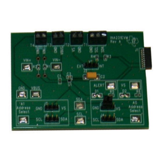
INA231EVM Documentation 6 INA231EVM Documentation This section contains the complete bill of materials, schematic diagram, and PCB layout for the INA231EVM. Note The board layout is not to scale. This image is intended to show how the board is laid out; it is not intended to be used for manufacturing INA231EVM PCBs. -
Page 22: Schematic
INA231EVM Documentation www.ti.com 6.1 Schematic Figure 6-1 shows the schematic for the INA231EVM. POWER JUMPER Test Points ALERT VIN+ VIN- JUMP3 4.7uF VBUS I2C_SCK CTL/MEAS4 VIN+ I2C_SDA ALERT VIN- CTL/MEAS5 ALERT ADDRESS SELECT PULLUP RESISTORS VBUS SPI_DOUT DVDD_INT VDUT .1uF... -
Page 23: Pcb Layout
INA231EVM Documentation 6.2 PCB Layout Figure 6-2 shows the component layout for the INA231EVM PCB. Figure 6-2. INA231EVM PCB Top Layer (Component Side) SBOU128A – FEBRUARY 2013 – REVISED MARCH 2023 INA231EVM (Rev A) Submit Document Feedback Copyright © 2023 Texas Instruments Incorporated... -
Page 24: Bill Of Materials
INA231EVM Documentation www.ti.com 6.3 Bill of Materials Table 6-1 lists the bill of materials for the INA231EVM. Table 6-1. Bill of Materials: INA231EVM REF DES DESCRIPTION VENDOR OR MANUFACTURER PART NUMBER R5, R6 Resistor, 10 kΩ 1/10 W 5% 0603 SMD... - Page 25 INA231EVM Documentation 6.2 PCB Layout Figure 6-2 shows the component layout for the INA231EVM PCB. Figure 6-2. INA231EVM PCB Top Layer (Component Side) SBOU128A – FEBRUARY 2013 – REVISED MARCH 2023 INA231EVM (Rev A) Submit Document Feedback Copyright © 2023 Texas Instruments Incorporated...
- Page 26 INA231EVM Documentation www.ti.com 6.3 Bill of Materials Table 6-1 lists the bill of materials for the INA231EVM. Table 6-1. Bill of Materials: INA231EVM REF DES DESCRIPTION VENDOR OR MANUFACTURER PART NUMBER R5, R6 Resistor, 10 kΩ 1/10 W 5% 0603 SMD...
-
Page 27: Revision History
NOTE: Page numbers for previous revisions may differ from page numbers in the current version. Changes from Revision * (February 2013) to Revision A (March 2023) Page • Changed user guide title for INA231EVM (Rev A) hardware support..............• Changed all instances of legacy terminology to controller and target where I C is mentioned......14... - Page 28 STANDARD TERMS FOR EVALUATION MODULES Delivery: TI delivers TI evaluation boards, kits, or modules, including any accompanying demonstration software, components, and/or documentation which may be provided together or separately (collectively, an “EVM” or “EVMs”) to the User (“User”) in accordance with the terms set forth herein.
- Page 29 www.ti.com Regulatory Notices: 3.1 United States 3.1.1 Notice applicable to EVMs not FCC-Approved: FCC NOTICE: This kit is designed to allow product developers to evaluate electronic components, circuitry, or software associated with the kit to determine whether to incorporate such items in a finished product and software developers to write software applications for use with the end product.
- Page 30 www.ti.com Concernant les EVMs avec antennes détachables Conformément à la réglementation d'Industrie Canada, le présent émetteur radio peut fonctionner avec une antenne d'un type et d'un gain maximal (ou inférieur) approuvé pour l'émetteur par Industrie Canada. Dans le but de réduire les risques de brouillage radioélectrique à...
- Page 31 www.ti.com EVM Use Restrictions and Warnings: 4.1 EVMS ARE NOT FOR USE IN FUNCTIONAL SAFETY AND/OR SAFETY CRITICAL EVALUATIONS, INCLUDING BUT NOT LIMITED TO EVALUATIONS OF LIFE SUPPORT APPLICATIONS. 4.2 User must read and apply the user guide and other available documentation provided by TI regarding the EVM prior to handling or using the EVM, including without limitation any warning or restriction notices.
- Page 32 Notwithstanding the foregoing, any judgment may be enforced in any United States or foreign court, and TI may seek injunctive relief in any United States or foreign court. Mailing Address: Texas Instruments, Post Office Box 655303, Dallas, Texas 75265 Copyright © 2023, Texas Instruments Incorporated...
- Page 33 TI products. TI’s provision of these resources does not expand or otherwise alter TI’s applicable warranties or warranty disclaimers for TI products. TI objects to and rejects any additional or different terms you may have proposed. IMPORTANT NOTICE Mailing Address: Texas Instruments, Post Office Box 655303, Dallas, Texas 75265 Copyright © 2023, Texas Instruments Incorporated...
Need help?
Do you have a question about the INA231EVM and is the answer not in the manual?
Questions and answers