Table of Contents
Advertisement
Quick Links
www.ti.com
User's Guide
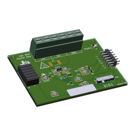
INA232EVM, INA234EVM and INA236EVM
This user's guide describes the characteristics, operation, and use of the INA232, INA234 and INA236
evaluation modules (EVMs). These EVMs are designed to evaluate the performance of the INA232, INA234 and
INA236. Throughout this document, the terms evaluation board, evaluation module, and EVM are synonymous
with the INA232EVM, INA234EVM and INA236EVM. This document includes a schematic, reference printed
circuit board (PCB) layouts, and a complete bill of materials (BOM).
SBOU264B – MAY 2021 – REVISED DECEMBER 2022
Submit Document Feedback
ABSTRACT
Copyright © 2022 Texas Instruments Incorporated
INA232EVM, INA234EVM and INA236EVM
1
Advertisement
Table of Contents

Related Manuals for Texas Instruments INA232EVM


Summary of Contents for Texas Instruments INA232EVM
- Page 1 (EVMs). These EVMs are designed to evaluate the performance of the INA232, INA234 and INA236. Throughout this document, the terms evaluation board, evaluation module, and EVM are synonymous with the INA232EVM, INA234EVM and INA236EVM. This document includes a schematic, reference printed circuit board (PCB) layouts, and a complete bill of materials (BOM).
-
Page 2: Table Of Contents
Table of Contents www.ti.com Table of Contents Trademarks....................................2 Overview....................................3 2.1 Kit Contents..................................3 2.2 Related Documentation From Texas Instruments......................3 Hardware....................................3.1 Features..................................... Operation....................................5 4.1 Quick Start Setup................................4.2 EVM Operation...................................5 5 Circuitry....................................5.1 Current Sensing IC................................19 5.2 Input Signal Path................................19 5.3 Digital Circuitry................................. -
Page 3: Overview
INA232EVM, INA234EVM OR INA236EVM board Note that this EVM requires the TI Sensor Control Board (SCB), which is sold separately. SBOU264B – MAY 2021 – REVISED DECEMBER 2022 INA232EVM, INA234EVM and INA236EVM Submit Document Feedback Copyright © 2022 Texas Instruments Incorporated... -
Page 4: Related Documentation From Texas Instruments
Newer revisions are available from www.ti.com or the Texas Instruments' Literature Response Center at (800) 477-8924 or the Product Information Center at (972) 644-5580. When ordering, identify the document by both title and literature number. -
Page 5: Operation
4-2. Make sure to use a different chip address for each device. The GUI only supports one EVM/device type at a time. SBOU264B – MAY 2021 – REVISED DECEMBER 2022 INA232EVM, INA234EVM and INA236EVM Submit Document Feedback Copyright © 2022 Texas Instruments Incorporated... - Page 6 While shorting the two test points labeled "DFU" (shown in Figure 4-3) with a pair of tweezers (or wire), press and release the RESET button. INA232EVM, INA234EVM and INA236EVM SBOU264B – MAY 2021 – REVISED DECEMBER 2022 Submit Document Feedback Copyright © 2022 Texas Instruments Incorporated...
- Page 7 2. Check to make sure the EVM/SCB Controller unit is plugged into the PC, then go to the previously-provided GUI link. 3. Click the GUI Composer application (Figure 4-4) to launch the GUI from the web browser. SBOU264B – MAY 2021 – REVISED DECEMBER 2022 INA232EVM, INA234EVM and INA236EVM Submit Document Feedback Copyright © 2022 Texas Instruments Incorporated...
- Page 8 If successful, the Hardware Connected message should be visible near the bottom-left corner of the GUI as in Figure 4-6. INA232EVM, INA234EVM and INA236EVM SBOU264B – MAY 2021 – REVISED DECEMBER 2022 Submit Document Feedback Copyright © 2022 Texas Instruments Incorporated...
- Page 9 If you are using the correct GUI/EVM combination, you may need to reprogram the firmware of the SCB, as described in Firmware Debug. SBOU264B – MAY 2021 – REVISED DECEMBER 2022 INA232EVM, INA234EVM and INA236EVM Submit Document Feedback Copyright © 2022 Texas Instruments Incorporated...
- Page 10 Figure 4-10. Configuration Tool INA232EVM, INA234EVM and INA236EVM SBOU264B – MAY 2021 – REVISED DECEMBER 2022 Submit Document Feedback Copyright © 2022 Texas Instruments Incorporated...
- Page 11 – If a Max Expected Current is not specified, then the True Max Current field will be used instead. SBOU264B – MAY 2021 – REVISED DECEMBER 2022 INA232EVM, INA234EVM and INA236EVM Submit Document Feedback Copyright © 2022 Texas Instruments Incorporated...
- Page 12 To do this, go to File > Register Data. (See Figure 4-12.) Figure 4-12. Save and Load Register Settings INA232EVM, INA234EVM and INA236EVM SBOU264B – MAY 2021 – REVISED DECEMBER 2022 Submit Document Feedback Copyright © 2022 Texas Instruments Incorporated...
- Page 13 Although you can read and write to other registers through the register map page while collecting data, it is possible that this adds a delay to the data being collected. SBOU264B – MAY 2021 – REVISED DECEMBER 2022 INA232EVM, INA234EVM and INA236EVM Submit Document Feedback Copyright © 2022 Texas Instruments Incorporated...
- Page 14 The General Call Start command is issued to trigger a simultaneous start of conversion among multiple devices. When this button is pressed, all devices will stop and restart a new conversion. INA232EVM, INA234EVM and INA236EVM SBOU264B – MAY 2021 – REVISED DECEMBER 2022 Submit Document Feedback Copyright © 2022 Texas Instruments Incorporated...
- Page 15 1. Connect a differential voltage across the IN+ and IN– terminals (see Figure 4-14). Note that INA234EVM or INA236EVM is used for illustration. In screw terminal J1, IN+ and IN– are swapped for the INA232EVM (see Figure 4-15). a. If the differential voltage supply is a floating supply, connect a –0.3-V to 48-V common-mode voltage (leave powered off until finished setting up) to the inputs by connecting the positive lead of the external voltage source to either the IN+ or IN–...
- Page 16 4. Connect the system ground to the GND terminal (J1 pin 1). 5. Power on the system, and observe the device states and outputs through the GUI. INA232EVM, INA234EVM and INA236EVM SBOU264B – MAY 2021 – REVISED DECEMBER 2022 Submit Document Feedback Copyright © 2022 Texas Instruments Incorporated...
- Page 17 – For the previous example, the EVM would return the results in JSON format: {"acknowledge":"wreg 0x01 0x4121"} {"console":"Writing 0x4121 to ADC_CONFIG register"} {"evm_state":"idle"} SBOU264B – MAY 2021 – REVISED DECEMBER 2022 INA232EVM, INA234EVM and INA236EVM Submit Document Feedback Copyright © 2022 Texas Instruments Incorporated...
- Page 18 Stop collecting data format: stop – The EVM would return the acknowledgment and status in JSON format: {"acknowledge":"stop"} {"evm_state":"idle"} INA232EVM, INA234EVM and INA236EVM SBOU264B – MAY 2021 – REVISED DECEMBER 2022 Submit Document Feedback Copyright © 2022 Texas Instruments Incorporated...
-
Page 19: Circuitry
R8 is used as a pullup resistor for the ALERT pin, which is routed to both J2 and J3. LED D2 and current limiting resistor R7 are used to indicate when the ALERT has triggered. SBOU264B – MAY 2021 – REVISED DECEMBER 2022 INA232EVM, INA234EVM and INA236EVM Submit Document Feedback Copyright © 2022 Texas Instruments Incorporated... -
Page 20: Schematics, Pcb Layout, And Bill Of Materials
ALERT 4.7k TP10 0.01 100V 0.1uF INA236AIYBJR +3V3 +3V3 +3V3 MNT_1 MNT_2 MNT_3 MNT_4 CUS-14TB Figure 6-1. SENS079 Schematic INA232EVM, INA234EVM and INA236EVM SBOU264B – MAY 2021 – REVISED DECEMBER 2022 Submit Document Feedback Copyright © 2022 Texas Instruments Incorporated... - Page 21 These assemblies must comply with workmanship standards IPC-A-610 Class 2, unless otherwise speci e d. ¤ Figure 6-2. SENS079 Hardware Schematic SBOU264B – MAY 2021 – REVISED DECEMBER 2022 INA232EVM, INA234EVM and INA236EVM Submit Document Feedback Copyright © 2022 Texas Instruments Incorporated...
- Page 22 Schematics, PCB Layout, and Bill of Materials www.ti.com 6.1.2 SENS090 (INA232EVM) Figure 6-3 shows the schematic of the SENS090 variant (INA232EVM). Figure 6-3. SENS090 Schematic INA232EVM, INA234EVM and INA236EVM SBOU264B – MAY 2021 – REVISED DECEMBER 2022 Submit Document Feedback...
-
Page 23: Pcb Layout
Figure 6-6. SENS079 Bottom View Figure 6-7. SENS079 Bottom Layer 6.2.2 SENS090 (INA232EVM) This section shows the PCB layers of the SENS090 variant (INA232EVM). Figure 6-9. SENS090 Top Layer Figure 6-8. SENS090 Top View SBOU264B – MAY 2021 – REVISED DECEMBER 2022... - Page 24 Schematics, PCB Layout, and Bill of Materials www.ti.com Figure 6-11. SENS090 Bottom Layer Figure 6-10. SENS090 Bottom View INA232EVM, INA234EVM and INA236EVM SBOU264B – MAY 2021 – REVISED DECEMBER 2022 Submit Document Feedback Copyright © 2022 Texas Instruments Incorporated...
-
Page 25: Bill Of Materials
10 mOhms ±0.5% 2W Chip Resistor 2512 (6432 Metric) Automotive AEC-Q200, 2512 PCS2512DR0100ET Ohmite Current Sense, Moisture Resistant Metal Film SBOU264B – MAY 2021 – REVISED DECEMBER 2022 INA232EVM, INA234EVM and INA236EVM Submit Document Feedback Copyright © 2022 Texas Instruments Incorporated... - Page 26 10 mOhms ±0.5% 2W Chip Resistor 2512 (6432 Metric) Automotive AEC-Q200, 2512 PCS2512DR0100ET Ohmite Current Sense, Moisture Resistant Metal Film INA232EVM, INA234EVM and INA236EVM SBOU264B – MAY 2021 – REVISED DECEMBER 2022 Submit Document Feedback Copyright © 2022 Texas Instruments Incorporated...
-
Page 27: Revision History
NOTE: Page numbers for previous revisions may differ from page numbers in the current version. Changes from Revision A (February 2022) to Revision B (December 2022) Page • Added the INA232EVM to the document......................3 Changes from Revision * (May 2021) to Revision A (February 2022) Page •... - Page 28 STANDARD TERMS FOR EVALUATION MODULES Delivery: TI delivers TI evaluation boards, kits, or modules, including any accompanying demonstration software, components, and/or documentation which may be provided together or separately (collectively, an “EVM” or “EVMs”) to the User (“User”) in accordance with the terms set forth herein.
- Page 29 www.ti.com Regulatory Notices: 3.1 United States 3.1.1 Notice applicable to EVMs not FCC-Approved: FCC NOTICE: This kit is designed to allow product developers to evaluate electronic components, circuitry, or software associated with the kit to determine whether to incorporate such items in a finished product and software developers to write software applications for use with the end product.
- Page 30 www.ti.com Concernant les EVMs avec antennes détachables Conformément à la réglementation d'Industrie Canada, le présent émetteur radio peut fonctionner avec une antenne d'un type et d'un gain maximal (ou inférieur) approuvé pour l'émetteur par Industrie Canada. Dans le but de réduire les risques de brouillage radioélectrique à...
- Page 31 www.ti.com EVM Use Restrictions and Warnings: 4.1 EVMS ARE NOT FOR USE IN FUNCTIONAL SAFETY AND/OR SAFETY CRITICAL EVALUATIONS, INCLUDING BUT NOT LIMITED TO EVALUATIONS OF LIFE SUPPORT APPLICATIONS. 4.2 User must read and apply the user guide and other available documentation provided by TI regarding the EVM prior to handling or using the EVM, including without limitation any warning or restriction notices.
- Page 32 Notwithstanding the foregoing, any judgment may be enforced in any United States or foreign court, and TI may seek injunctive relief in any United States or foreign court. Mailing Address: Texas Instruments, Post Office Box 655303, Dallas, Texas 75265 Copyright © 2019, Texas Instruments Incorporated...
- Page 33 TI products. TI’s provision of these resources does not expand or otherwise alter TI’s applicable warranties or warranty disclaimers for TI products. TI objects to and rejects any additional or different terms you may have proposed. IMPORTANT NOTICE Mailing Address: Texas Instruments, Post Office Box 655303, Dallas, Texas 75265 Copyright © 2022, Texas Instruments Incorporated...
Need help?
Do you have a question about the INA232EVM and is the answer not in the manual?
Questions and answers