Schwinn 190 Assembly Manual / Owner's Manual
Hide thumbs
Also See for 190:
- Service manual (100 pages) ,
- Troubleshooting manual (6 pages) ,
- Quick start manual (6 pages)

Related Manuals for Schwinn 190


Summary of Contents for Schwinn 190
- Page 1 Manuals in additional languages: ASSEMBLY MANUAL / OWNER’S MANUAL http://www.schwinnfitness.com...
-
Page 2: Table Of Contents
TABLE OF CONTENTS Important Safety Instructions Operation Safety Warning Labels / Serial Number Adjustments Power Up / Idle Mode Manual (Quick Start) Program Parts Hardware Tools Assembly Summary Mode Leveling the Bike Console Setup Mode Moving the Bike Maintenance Features Maintenance Parts Console Features Troubleshooting... -
Page 3: Important Safety Instructions
IMPORTANT SAFETY INSTRUCTIONS This icon means a potentially hazardous situation which, if not avoided, could result in death or serious injury. Obey the following warnings: Read and understand all warnings on this machine. Carefully read and understand the Assembly instructions. •... - Page 4 • Disconnect all power before servicing this machine. • Do not operate this machine outdoors or in moist or wet locations. Keep the foot pedals clean and dry. • is the recommended safe distance for access, passage and emergency dismounts from the machine. Keep third parties out of this space when machine is in use.
-
Page 5: Safety Warning Labels / Serial Number
SAFETY WARNING LABELS AND SERIAL NUMBER WARNING! Read, understand and obey all warnings on this machine. Keep children away. Not intended for use by anyone under 14 years of age. Refer to owner’s manual for additional warnings and safety information. Injury or death is possible if caution is not used while using this this machine is 330 LBS (150 KG). - Page 6 SPECIFICATIONS Maximum User Weight: 150 kg ( 330 lb ) Total Surface Area (footprint) of equipment: 9790.8 cm (1518.1 in Machine Weight: Power Requirements (AC Adapter): Input Voltage: Output Voltage: 12V DC, 3A 144.3 cm (56.8 in) 119.4 cm (47 in) 82 cm (32.3 in) DO NOT dispose of this product as refuse.
-
Page 7: Parts
PARTS 15 (L) 16 (R) Item Description Item Description Main Assembly Console Mount Bracket Rear Stabilizer Media Tray * Front Stabilizer, Right Pivot Cover Front Stabilizer, Left Seat Post Top Shroud Seat Console Mast (with Handlebar Mount) Left Pedal (L) Handlebars Right Pedal (R) Handlebar Mount Cover... -
Page 8: Hardware
HARDWARE / TOOLS Item Description Item Description Leveler Foot Flat Washer, Narrow, M8 Handlebar Clamp Handle Flange Lock Nut, Serrated, M8 Spring Washer, M8 Note: Selected pieces of Hardware have been provided as spares on the Hardware Card. The spare Screw (*) is for the Water Bottle Holder. -
Page 9: Assembly
ASSEMBLY 1. Attach Leveler Feet to Rear Stabilizer and Attach Stabilizers to Main Assembly Note: Hardware(*) is pre-installed on the Stabilizers and not on Hardware Card. Carefully remove packaging material in Rear Stabilizer bracket and under the Top Shroud (5) and discard safely. Do not secure the Top Shroud at this time. - Page 10 2. Connect the Cables and Install Console Mast on Frame Assembly NOTICE: Remove the pre-installed hardware(*) from the mast mount. The Frame cable connector (1a) is attached to the plastic insert in the mast mount. Leave the plastic insert and Frame cable connector in place and carefully connect the Console Mast cable.
- Page 11 3. Install Handlebars on Console Mast NOTICE: Install the Handlebar Clamp Handle (B) through the holes. Fully tighten the Handle to keep the Handlebar in position. Note: To install the Handlebar Mount Cover (8), it may be necessary to spread the opening (8a) slightly before pushing it down into position on the Handlebar Mount.
- Page 12 5a. Remove Console Screws Note: Remove the pre-installed screws (*) from the back of the Console. NOTICE: Do not let the screws fall inside the Console. Do not cut or pinch the cable. 5b. Install the Console Assembly on the Console Mast NOTICE: Do not cut or pinch the cables.
- Page 13 5c. Install the Pivot Cover and Media Tray NOTICE: Do not cut or pinch the cables. Note: Remove the adhesive backing from the Media Tray. Slide the tabs into the slots on the Console face and rotate the Media Tray downward. Press it firmly and evenly against the Console face to attach the adhesive surface securely.
- Page 14 7. Install the Seat to the Seat Post NOTICE: Do not loosen the Seat nuts (14b) on the Seat bracket (14a) before sliding the Seat onto the post. Be sure the Seat is straight and level. Hold the Seat in position and fully tighten both nuts to secure the Seat. Tighten the adjustment handle (13c) to secure the seat slider.
- Page 15 9. Install Water Bottle Holder Note: The hardware(*) is pre-installed on the Console Mast. 10. Connect AC Adapter NOTICE: Make sure the connector is pushed all the way into the Power Inlet on the machine.
- Page 16 11. Final Inspection Inspect your machine to ensure that all hardware is tight and components are properly assembled. Be sure to record the serial number in the field provided at the front of this manual. Carefully remove the protective plastic film from the display screen, keypad and top of the Console. Due to static electricity, “ghost”...
-
Page 17: Leveling The Bike
BEFORE YOU START Leveling the Bike Levelers are found on each side of the Rear Stabilizer. Turn the adjustment nut to adjust the stabilizer foot. Do not adjust the levelers to such a height that they detach or unscrew from the machine. Injury to you or damage to the machine can occur. -
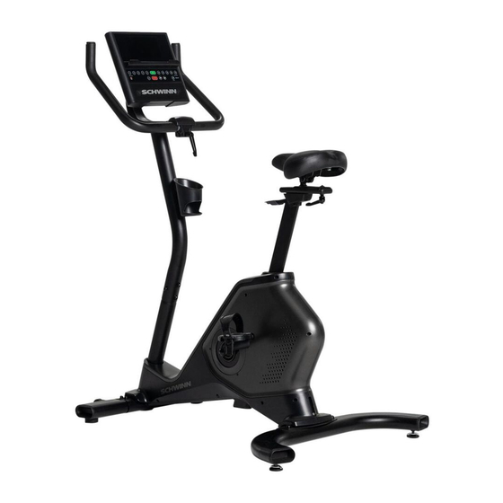
Page 18: Features
FEATURES Console Seat Slider Adjustable Console Mount Seat Handlebars Seat Adjustment Lever Step-through Frame Water Bottle Holder Transport Rollers Speakers Stabilizers Media Tray Pedals USB Port Levelers AC Adapter Power Connector Bluetooth ® Heart Rate (HR) Receiver (not shown) Fully Shrouded Flywheel Bluetooth Connectivity (not shown) ®... -
Page 19: Console Features
Increase ( ) button- Increases the workout resistance level or moves through options. Decrease ( ) button- Decreases the workout resistance level or moves through options. It does Reset button (Schwinn logo)- for service technician use only. When pushed during power up, the button restores the ™... - Page 20 Bluetooth App Connected icon ® Bluetooth Heart ® Rate Monitor Connected icon Heart Rate Detected icon Program Display Console Display Bluetooth ® App Connected icon - Display shows when the Console is paired with the App. Bluetooth Heart Rate Monitor Connected icon - Display shows when the Console is paired with a Bluetooth Heart Rate ®...
- Page 21 Heart Rate (Pulse) Consult a physician before you start an exercise program. Stop exercising if you feel pain or tightness in your chest, become short of breath, or feel faint. Contact your doctor before you use the machine again. The heart rate displayed is an approximation and should be used for reference only. Distance The default distance unit is miles (MI).
-
Page 22: Bluetooth ® Heart Rate Monitor
USB Charging If a USB Device is attached to the USB Port, the Port will attempt to charge the Device. Depending on the amperage of device, the power supplied from the USB Port may not be enough to operate the Device and charge it at the same time. Workout with Other Fitness Apps ®... - Page 23 Note: Be sure to remove the protective cover (if provided) from the Heart Rate Sensor before use. 1. Put on your Bluetooth ® Heart Rate monitor and activate it. Heart Rate Monitor ® Connected icon. 3. When connected, the Bluetooth ®...
-
Page 24: Operation
OPERATION What to Wear How Often Should You Exercise Consult a physician before you start an exercise program. Stop exercising if you feel pain or tightness in your chest, become short of breath, or feel faint. Contact your doctor before you use the machine again. Use the values calculated or measured by the machine’s computer for reference purposes only. -
Page 25: Manual (Quick Start) Program
while in Sleep Mode. Note: The Console does not have an On/Off switch. Manual (Quick Start) Program The Manual (Quick Start) program lets you start a workout without entering any information. During a Manual Workout, each column represents a 1 minute time period. The active column will advance across the screen every minute. - Page 26 Non-Interval Programs Fat Burn Calorie Burn Rolling Hills Summit Pass Stairs Modify Display of Workout Values To switch units between kilometers and miles before a workout, push the Programs button and hold for 3 seconds to enter the Console Setup Mode. The System Units prompt appears. Push an Increase/Decrease button to change the units (KM/ KG or MI/LB).
-
Page 27: Summary Mode
Muting the Console The Console has the option to be muted. To disable the audible cues, tap the Volume button to cycle through the volume Note: The Console will reset to the last volume setting for the selected User Profile after each power-up. Workout Summary Mode After a workout, the Console display will show "Workout Complete"... -
Page 28: Console Setup Mode
CONSOLE SETUP MODE Console Setup Mode – System Menu The Console Setup Mode allows you to set units of measurement to either Imperial or metric, adjust screen brightness, Console. 1. Push the Programs button and hold for 3 seconds while in the Power-Up Mode to go into the Console Setup Mode (System Menu). - Page 29 starting Reset. Note: the Run Time Hours. 27. The Console will display the Power-Up Mode screen.
-
Page 30: Maintenance
MAINTENANCE Read all maintenance instructions fully before you start any repair work. In some conditions, an assistant is necessary to do the necessary tasks. Equipment must be regularly examined for damage and repairs. The owner is responsible to make sure that regular maintenance is done. -
Page 31: Maintenance Parts
Maintenance Parts Console Crank Arms Handlebar Clamp Handle Console Mount Bracket Rear Stabilizer Handlebar Mount Cover Media Tray Power Inlet Drive Belt Console Mast AC Adapter Flywheel Pivot Cover Levelers Magnet Carriage Data Cable, Upper Left Shroud Resistance Sensor Insert, Lower Mast Bolt Catch Shroud Resistance Magnet Front Stabilizer, Left... -
Page 32: Troubleshooting
TROUBLESHOOTING Condition/Problem Things to Check Solution No display/partial display/ Check electrical (wall) Make sure unit is plugged into a functioning wall outlet. unit will not turn on outlet Check connection at front Connection should be secure and undamaged. Replace of unit adapter or connection at unit if either are damaged. - Page 33 Be sure adjustment pin is locked into one of the seat post adjustment holes. Check adjustment knob Be sure knob is securely tightened. Console continuously Console is in demonstra- Press and hold the Schwinn ™ logo button for 3 seconds. The cycles through program tion mode screens...
-
Page 35: Warranty (Us/Canada Only)
WARRANTY ( if purchased in US/Canada ) Who Is Covered This warranty is valid only to the original purchaser and is not transferable or applicable to any other person(s). What Is Covered Nautilus, Inc. warrants that this product is free from defects in materials and workmanship, when used for the purpose intended, under normal conditions, and provided it receives proper care and maintenance as described in the Product’s Assembly and Owner’s manual. - Page 36 ™ ™ ™ ™ ™ ™ 8028247.050122.B...
Need help?
Do you have a question about the 190 and is the answer not in the manual?
Questions and answers
do you put in weight and age on the keyboard