
Related Manuals for Allen-Bradley MicroLogix 1762-IF4


Summary of Contents for Allen-Bradley MicroLogix 1762-IF4
-
Page 1: Table Of Contents
Installation Instructions MicroLogix 1762-IF4 Analog Input Module Catalog Number 1762-IF4 Table of Contents Topic Page Important User Information North American Hazardous Location Approval Additional Resources Overview Module Description Mount the Module Field Wiring Connections Input Type Selection Wiring the Finger-Safe Terminal Block... -
Page 2: Important User Information
MicroLogix 1762-IF4 Analog Input Module Important User Information Solid state equipment has operational characteristics differing from those of electromechanical equipment. Safety Guidelines for the Application, Installation and Maintenance of Solid State Controls (Publication SGI-1.1 available from your local Rockwell Automation sales office or online at http://literature.rockwellautomation.com) describes some important differences between solid state... - Page 3 MicroLogix 1762-IF4 Analog Input Module Environment and Enclosure This equipment is intended for use in a Pollution Degree 2 industrial ATTENTION environment, in overvoltage Category II applications (as defined in IEC 60664-1), at altitudes up to 2000 m (6562 ft) without derating.This equipment is considered Group 1, Class A industrial equipment according to IEC/CISPR 11.
-
Page 4: North American Hazardous Location Approval
MicroLogix 1762-IF4 Analog Input Module North American Hazardous Location Approval The following modules are North American Hazardous Location approved: 1762-IF4 The following information applies when Informations sur l’utilisation de cet operating this equipment in hazardous équipement en environnements dangereux: locations: Products marked "CL I, DIV 2, GP A, B, C, D"... -
Page 5: Additional Resources
Guidelines, publication 1770-4.1. techniques. If you would like a manual, you can: • download a free electronic version from the Internet: http://literature.rockwellautomation.com • purchase a printed manual by contacting your local Allen-Bradley distributor or Rockwell Automation representative Publication 1762-IN012C-EN-P - June 2013... -
Page 6: Overview
MicroLogix 1762-IF4 Analog Input Module Overview The 1762 input module is suitable for use in an industrial environment when installed in accordance with these instructions. Specifically, this equipment is intended for use in clean, dry environments (Pollution degree 2 ) and to circuits not exceeding Over Voltage Category II (IEC 60664-1) Install your module using these installation instructions. -
Page 7: Module Description
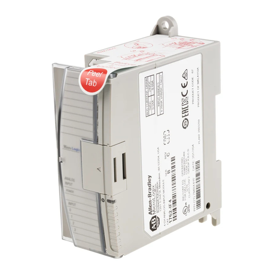
MicroLogix 1762-IF4 Analog Input Module Module Description 45156 Left side view Front view 45157 This equipment is sensitive to electrostatic discharge (ESD). Follow ESD prevention guidelines when handling this equipment. Description Description upper panel mounting tab pull loop lower panel mounting tab... -
Page 8: Mount The Module
Additional grounding connections from the power supply's mounting tabs or DIN rail (if used) are not required unless the mounting surface cannot be grounded. Refer to Industrial Automation Wiring and Grounding Guidelines, Allen-Bradley publication 1770-4.1, for additional information. Mounting Dimensions 90 mm (3.5 in.) - Page 9 Before mounting the module on a DIN rail, close the DIN rail latch. Press the DIN rail mounting area of the module against the DIN rail. The latch will momentarily open and lock into place. Use DIN rail end anchors (Allen-Bradley part number 1492-EA35 or 1492-EAH35) for vibration or shock environments. End anchor...
- Page 10 MicroLogix 1762-IF4 Analog Input Module Panel Mounting Use the dimensional template shown below to mount the module. The preferred mounting method is to use two M4 (#8) panhead screws per module. M3.5 (#6) panhead screws may also be used, but a washer may be needed to ensure a good mechanical contact. Mounting screws are required on every module.
-
Page 11: Field Wiring Connections
MicroLogix 1762-IF4 Analog Input Module Field Wiring Connections Grounding the Module In solid-state control systems, grounding and wire routing helps limit the effects of noise due to electromagnetic interference (EMI). Run the ground connection from the ground screw of the controller to the ground bus prior to connecting any devices. -
Page 12: Input Type Selection
MicroLogix 1762-IF4 Analog Input Module Input Type Selection elect the input type, current or voltage, using the switch located on the module’s circuit board and the input type/range selection bits in the Configuration Data File (see page 17). You can access the switch through the ventilation slots on the top of the module. - Page 13 MicroLogix 1762-IF4 Analog Input Module Basic Input Wiring to the 1762-IF4 Module Differential Sensor Transmitter Types IN 0 (+) Analog Sensor IN 0 (-) IN 1 (+) IN 1 (-) IN 2 (+) IN 2 (-) IN 3 (+) IN 3 (-) Grounding the cable shield at the module end only usually provides sufficient noise immunity.
- Page 14 MicroLogix 1762-IF4 Analog Input Module Sensor/Transmitter Types Module 2-Wire Transmitter Transmitter Power IN + Supply IN - Transmitter Module 3-Wire Transmitter Supply Signal Power IN + Supply IN - Module Transmitter 4-Wire Transmitter Supply Signal Power IN + Supply IN - (1) All power supplies rated N.E.C.
-
Page 15: Wiring The Finger-Safe Terminal Block
MicroLogix 1762-IF4 Analog Input Module Wiring the Finger-Safe Terminal Block ATTENTION Be careful when stripping wires. Wire fragments that fall into a module could cause damage when power is applied. Once wiring is complete, ensure the module is free of all metal fragments. - Page 16 MicroLogix 1762-IF4 Analog Input Module Labeling the Terminals A write-on label is provided with the module. Mark the identification of each terminal with permanent ink, and slide the label back into the door. 1762 Expansion I/O Addressing The addressing scheme for 1762 Expansion I/O is represented in the following figure.
- Page 17 MicroLogix 1762-IF4 Analog Input Module The bits are defined as follows: • Sx = General status bits for channels 0…3. This bit is set when an error (over- or under-range) exists for that channel, or there is a general module hardware error.
- Page 18 MicroLogix 1762-IF4 Analog Input Module Data Format (Bits 14 … These bits indicate the format of the data as shown in the following table. Other combinations of these bits are not supported and result in an error. Bit Settings Data Format...
-
Page 19: Error Codes
MicroLogix 1762-IF4 Analog Input Module Error Codes The 1762-IF4 module notifies the controller of critical and non-critical errors. The module condition array word 0 contains the error codes that are generated by the module, as shown below. “Don’t Care” Bits... -
Page 20: Specifications
MicroLogix 1762-IF4 Analog Input Module Specifications Input Attribute Value Number of inputs 4 differential (bipolar) A/D converter type Sigma-Delta ±27V Common mode voltage range > 55 dB @ 50 and 60 Hz Common mode rejection Non-linearity (in percent full scale) ±0.12%... - Page 21 MicroLogix 1762-IF4 Analog Input Module General Attribute Value Dimensions, HxWxD 90 x 40.4 x 87 mm (3.54 x 1.59 x 3.43 in.) Approximate shipping weight (with carton) 235 g (8.28 oz) Bus current draw, max 40 mA @ 5V DC...
- Page 22 MicroLogix 1762-IF4 Analog Input Module Environmental Attribute Value Temperature, operating IEC 60068-2-1 (Test Ad, Operating Cold), IEC 60068-2-2 (Test Bd, Operating Dry Heat), IEC 60068-2-14 (Test Nb, Operating Thermal Shock): -20... 65 °C (-4...149 °F) Temperature, storage IEC 60068-2-1 (Test Ab, Unpackaged Non-operating Cold),...
- Page 23 MicroLogix 1762-IF4 Analog Input Module Certifications Certification (when Value product is marked) c-UL-us UL Listed Industrial Control Equipment, certified for US and Canada. See UL File E322657. UL Listed for Class I, Division 2 Group A,B,C,D Hazardous Locations, certified for U.S.
Need help?
Do you have a question about the MicroLogix 1762-IF4 and is the answer not in the manual?
Questions and answers