
Related Manuals for Allen-Bradley POINT I/O PROFIBUS 1734-APB


Summary of Contents for Allen-Bradley POINT I/O PROFIBUS 1734-APB
- Page 1 POINT I/O PROFIBUS Adapter Module Cat. No. 1734-APB User Manual Allen-Bradley HMIs...
-
Page 2: Important User Information
• avoid a hazard • recognize the consequences Identifies information that is critical for successful IMPORTANT application and understanding of the product. Allen-Bradley, RSNetworx and POINT I/O are trademarks of Rockwell Automation PROFIBUS is a trademark of PROFIBUS Trade Organization... -
Page 3: Preface
1734-IN052 220V ac Input Module Installation Instructions 1734-IM 1734-IN008 120V ac Input Module Installation Instructions 1734-IA2 1734-IN010 120/220V ac Output Module Installation Instructions 1734-OA2 1734-IN009 Analog Current Input Module Installation Instructions 1734-IE2C 1734-IN053 Allen-Bradley HMIs Publication 1734-UM005B-EN-P - June 2001... - Page 4 Preface Description Cat. No. Publication Analog Current Output Module Installation Instructions 1734-OE2C 1734-IN054 Analog Voltage Input Module Installation Instructions 1734-IE2V 1734-IN001 Analog Voltage Output Module Installation Instructions 1734-OE2V 1734-IN002 Very High Speed Counter Module Installation Instructions 1734-VHSC24 1734-IN003 Very High Speed Counter Module Installation Instructions 1734-VHSC5 1734-IN004 5V Encoder/Counter Module Installation Instructions...
-
Page 5: European Communities (Ec) Directive Compliance
See NEMA Standards publication 250 and IEC publication 529, as applicable, for explanations of the degrees of protection provided by different types of enclosures. Refer to Allen-Bradley publication 1770-4.1, Industrial Automation Wiring and Grounding Guidelines for more information. Allen-Bradley HMIs... - Page 6 Preface Publication 1734-UM005B-EN-P - June 2001...
-
Page 7: Table Of Contents
Download to Master System ..... . . 3-13 Allen-Bradley HMIs Chapter Summary and What’s Next ....3-14... - Page 8 Table of Contents Chapter 4 Communication and I/O Table In This Chapter ....... . . 4-1 Image Table Mapping .
- Page 9 Configuration Data: ......B-14 Diagnostic Data ......B-14 Allen-Bradley HMIs Publication 1734-UM005B-EN-P - June 2001...
- Page 10 Table of Contents 1734-IA2 120V ac Input Module....B-15 Product Code: 1111h ......B-15 Data Map: .
-
Page 11: What Is The Profibus Adapter
• PROFIBUS - adapter serves as a slave that exchanges I/O data with a PROFIBUS master. • PointBus - the adapter serves as a master that communicates with up to 63 POINT I/O modules Allen-Bradley HMIs Publication 1734-UM005B-EN-P - June 2001... -
Page 12: Communicating Through The Adapter
What is the PROFIBUS Adapter Communicating through the Adapter Output data is sent from the master across the PROFIBUS network to the 1734-APB adapter. The adapter automatically transfers the data across the PointBus backplane to the output modules. Inputs from the input modules are collected by the PROFIBUS adapter via the backplane and sent across the PROFIBUS network to the master. -
Page 13: Configure The Adapter For Profibus Communication
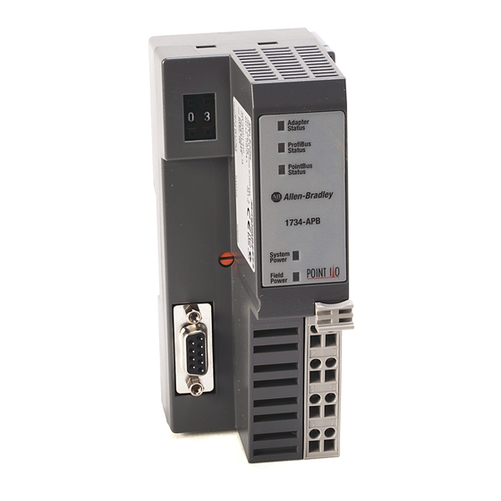
PointBus Status Status 1734-APB System Power System Power Field Field Power Power Profibus CHAS GND CHAS GND Connector NC = No Connection CHAS GND = Chassis Ground C = Common V = Supply Allen-Bradley HMIs Publication 1734-UM005B-EN-P - June 2001... -
Page 14: Diagnostic Indicators
What is the PROFIBUS Adapter Diagnostic Indicators Diagnostic indicators are located on the front panel of the adapter module. They show both normal operation and error conditions in your POINT I/O system. The indicators are: • Adapter status • PROFIBUS status •... -
Page 15: Installing The Profibus Adapter
If you choose not to use zinc plated, yellow chromated steel DIN rail for your POINT I/O, periodically clean the DIN rail to prevent or lessen the effects of oxidation and corrosion. Allen-Bradley HMIs Publication 1734-UM005B-EN-P - June 2001... - Page 16 Installing the PROFIBUS Adapter Installing the PROFIBUS To install the adapter on the DIN rail prior to installing other base units, proceed as follows. Adapter 1. Position the adapter vertically above the DIN rail. 2. Press down firmly to install the adapter on the DIN rail. (The locking mechanism will lock the adapter to the DIN rail.) 1734-APB communication interface DIN rail...
- Page 17 Do not discard the safety end cap. Use this end cap ATTENTION to cover the exposed interconnections on the last mounting base on the DIN rail. Failure to do so could result in equipment damage or injury from electric shock. Allen-Bradley HMIs Publication 1734-UM005B-EN-P - June 2001...
-
Page 18: Installing A Replacement Profibus Adapter To An Existing System
Installing the PROFIBUS Adapter Installing a Replacement 1. Remove the existing adapter from the DIN rail as follows: PROFIBUS Adapter to an A. Pull up on the removable terminal base (RTB) removal Existing System handle (7) to remove the terminal block. RTB removal handle B. - Page 19 (Make certain the DIN rail lock is in the horizontal position.) Slide the adapter down, allowing the interlocking side pieces to engage the adjacent module. Align the interlocking side pieces and slide adapter into place on the DIN rail. Allen-Bradley HMIs Publication 1734-UM005B-EN-P - June 2001...
-
Page 20: Wiring The Profibus Adapter
Installing the PROFIBUS Adapter 5. Press firmly to seat the adapter (1) on the DIN rail. The adapter locking mechanism will snap into place. 6. Insert the PROFIBUS network plug and tighten the holding screws. 7. Insert the end opposite the handle into the base unit. This end has a curved section that engages with the wiring base. - Page 21 180mA 1734-VHSC24 180mA For more information on the Expansion Power Supply, cat. no. 1734-EP24DC, refer to: • POINT I/O Technical Data, publication 1734-TD001A • POINT I/O Expansion Power Supply Installation Instructions, publication 1734-IN058A Allen-Bradley HMIs Publication 1734-UM005B-EN-P - June 2001...
-
Page 22: Wiring Connections
Installing the PROFIBUS Adapter Wiring Connections 12/24V dc Do not connect 120/240V ac power to this supply. CHAS GND CHAS GND This dc supply will be NC = No Connection connected to the CHAS GND = Chassis Ground internal power bus. V dc C = Common V = Supply... -
Page 23: Profibus Connection Plug Wiring
Negative RX/TX data line Not connected Chapter Summary and In this chapter, you learned how to install and wire your adapter. Move to chapter 3 for information on configuring the POINT I/O What’s Next system. Allen-Bradley HMIs Publication 1734-UM005B-EN-P - June 2001... - Page 24 2-10 Installing the PROFIBUS Adapter Publication 1734-UM005B-EN-P - June 2001...
-
Page 25: Configuring The Point I/O System
You must follow these steps during configuration: 1. Install the GSD file 2. Add the adapter to your PROFIBUS network 3. Add I/O modules to the adapter 4. Configure the modules Allen-Bradley HMIs 5. Download to master system Publication 1734-UM005B-EN-P - June 2001... -
Page 26: Installing The Gsd File
Configuring the POINT I/O System Installing the GSD File 1. Open file. Select the GSD file (173404EF.GSD) included on the diskette you received with your shipment of the adapter. This dialog indicates that the GSD file was successfully imported into the configuration tool. -
Page 27: Adding The Master To The Network
Select the “Master” entry in the “Insert” menu. 1. Select “PROFIBUS-DP Master” in the list called “Available Select station address here. Masters.” 2. Click “Add>>”. Type a description here. The master appears on the network. Allen-Bradley HMIs Publication 1734-UM005B-EN-P - June 2001... - Page 28 Configuring the POINT I/O System Select the master icon Select the “Bus Parameters” entry in the “Settings” menu. lSelect the required baud rate from the list. (Click “OK” to continue.) Publication 1734-UM005B-EN-P - June 2001...
-
Page 29: Adding The Adapter To The Network
Select the “Slave” entry in the “Insert” menu. 1. Select “1734-APB” in the “Available Slaves” list. Select station address here. 2. Click “Add>>”. (Click “OK” to continue.) Type a description here. The slave appears on the network. Allen-Bradley HMIs Publication 1734-UM005B-EN-P - June 2001... -
Page 30: Adding I/O Modules To The Adapter
Configuring the POINT I/O System Adding I/O Modules to the After you add the adapter, you must add the POINT I/O modules connected to the adapter in the backplane. Adapter You can select any of 5 different types: 1. Modules with Configuration Data If you select modules with configuration data (i.e. - Page 31 To add modules, double-click on the slave icon. Double click on the slave icon to add modules to your adapter. 1. Double click on the module you wish to add. 2. The module appears in the list below. Allen-Bradley HMIs Publication 1734-UM005B-EN-P - June 2001...
-
Page 32: Configuring I/O Modules
Configuring the POINT I/O System Configuring I/O Modules Most I/O modules have configuration data associated with them. This configuration data can be set manually. For a detailed description of the configuration data supported for different modules, refer to Appendix B. The configuration you select is transferred to the adapter with the PROFIBUS Set_parameter service. - Page 33 Select the value you wish to use, and click “OK.” Available parameters are module dependant. However, some parameters are common for all module types. These parameters are: Extended Diagnostics, Fault Action and Idle Action. Allen-Bradley HMIs Publication 1734-UM005B-EN-P - June 2001...
-
Page 34: Enable/Disable Diagnostic Functionality For Your Modules
3-10 Configuring the POINT I/O System Enable/Disable Diagnostic Functionality for your Modules The diagnostic functionality is enabled at default, but may be turned off (disabled) at the module level. When the diagnostic is disabled, the module will not report any diagnostic information to the adapter. Refer to chapter 4 for more information on module diagnostics. -
Page 35: Configure Idle Action Value For Your Output Modules
I/O modules into their Idle state. Select the “Idle Value” parameter. (Click on “OK” to continue.) Module parameters Select the desired state. Possible settings are “Idle Value,” and “Hold Last State (HLS). (Click on “OK” to continue.) Allen-Bradley HMIs Publication 1734-UM005B-EN-P - June 2001... - Page 36 3-12 Configuring the POINT I/O System If you select “Hold Last State,” the module outputs are frozen in their current state if power to the module is lost. If you select “Idle Value,” you need to define the Idle Value parameter. Possible settings are: digital modules - ON/OFF;...
-
Page 37: Download To Master System
(Click “OK” to continue.) Select port “COM 2. (Click “OK” to continue.) If the download is done during bus operation, the communication between master and slave is stopped. Confirm the download by clicking “Yes.” Downloading... Allen-Bradley HMIs Publication 1734-UM005B-EN-P - June 2001... -
Page 38: Chapter Summary And What's Next
3-14 Configuring the POINT I/O System Chapter Summary and In this chapter, you learned how to configure the POINT I/O system. Go to chapter 4 for information about communication and I/O table What’s Next mapping. Publication 1734-UM005B-EN-P - June 2001... -
Page 39: Image Table Mapping
The length of each module’s read bytes and write bytes vary in size depending on module complexity. The following illustration shows how the adapter maps information. Refer to appendix B for the data maps of the different POINT I/O modules. Allen-Bradley HMIs Publication 1734-UM005B-EN-P - June 2001... -
Page 40: How Data Communication Takes Place
Communication and I/O Table Mapping How Data Communication Before any data transfer can take place, the adapter has to verify and accept the PROFIBUS services Set_Parameter and Takes Place Check_Configuration that are sent from the master at startup. If the adapter accepts these services, data transmission is executed automatically in a cyclic manner with the Data_Exchange service. -
Page 41: Set_Parameter
The first two bytes define the product code for the installed module, the third byte defines the control byte followed by configuration data (if used). Allen-Bradley HMIs Publication 1734-UM005B-EN-P - June 2001... - Page 42 Communication and I/O Table Mapping Octet Bit 7 Bit 6 Bit 5 Bit 4 Bit 3 Bit 2 Bit 1 Bit 0 Reserved Product Code High Byte of First Module Product Code Low Byte of First Module Control Byte for First Module Configuration Data for First Module* Product Code High Byte for last Module X + 1...
- Page 43 1734-IB4 Product Code Low Byte 1734-IB4 Control Byte 1734-IB4 Configuration Data 1734-OE2C Product Code High Byte 1734-OE2C Product Code Low Byte 1734-OE2C Control Byte 1734-OE2C Configuration Data byte 1 Allen-Bradley HMIs 1734-OE2C Configuration Data byte 2 Publication 1734-UM005B-EN-P - June 2001...
-
Page 44: Check_Configuration
Communication and I/O Table Mapping Octet Value Description 1734-OE2C Configuration Data byte 3 1734-OE2C Configuration Data byte 4 1734-OE2C Configuration Data byte 5 1734-OE2C Configuration Data byte 6 1734-OE2C Configuration Data byte 7 1734-OE2C Configuration Data byte 8 1734-OE2C Configuration Data byte 9 Check_Configuration After the set_parameter service, the master sends a check_configuration service to the adapter. - Page 45 Byte 11 = 0x00; product code (high byte) bytes of I/O Byte 12 = 0x85; product code (low byte) data Byte 13 = 0xC2; control byte (diagnostics enabled, bit stuffing module, 2 bits (channels) to store in the opened byte. Allen-Bradley HMIs Publication 1734-UM005B-EN-P - June 2001...
-
Page 46: Get_Configuration
Communication and I/O Table Mapping Get_Configuration This service permits the master to read out the Identifier bytes for the actual adapter configuration. (Refer to the previous section for the format of the identifier byte.) The table below shows an example of how the identifier bytes from a Get_configuration response would look like when you have the following modules in the backplane: slot 1 = 1734-OB4E;... -
Page 47: Data_Exchange
DIN 19245-3 • Module related diagnostics indicates which I/O module has diagnostic events pending. • Channel related diagnostics, give more detailed information of the actual cause of the event (wire-break, overcurrent, etc.). Allen-Bradley HMIs Publication 1734-UM005B-EN-P - June 2001... - Page 48 4-10 Communication and I/O Table Mapping Structure of Slave_Diagnosis Octet Description Station Status 1 Station Status 2 Station Status 3 Master PROFIBUS address Identifier number (high byte) Identifier number (low byte) Module-related header byte 7-14 Module-related diagnostic block 15-17 1st channel-related diagnostic message 18-20 2nd channel-related diagnostic message 42-44...
- Page 49 Allen-Bradley HMIs Publication 1734-UM005B-EN-P - June 2001...
- Page 50 4-12 Communication and I/O Table Mapping Station Status 2 Description Cause 0 - Parameterization The slave has forced the This bit is set as long as new requested master system to do a new parameterization must be performed. parameterization. 1 - Static diagnostic The adapter cannot provide The backplane bus communication is valid I/O data.
- Page 51 Module 63 Module 62 Module 61 Module 60 Module 59 Module 58 Module 57 Channel Related Diagnostics These diagnostics give information on channel errors of the I/O modules and expand on the module related diagnostics. The message entry length is 3 bytes. Allen-Bradley HMIs Publication 1734-UM005B-EN-P - June 2001...
- Page 52 4-14 Communication and I/O Table Mapping A maximum of 10 channel related diagnostic messages are possible. If you exceed the limit, the diagnostic overflow bit in station status 3 will be set. Note: If the diagnostic buffer is full and the adapter receives an additional error message, this new message will be queued in the adapter internally and passed on to the master as soon as space is available in the diagnostic buffer (i.e.
- Page 53 Station status 1 - 3 Station status 1 - 3 1. Select error message Interpreted view of diagnostic messages 2. A detailed description Error details appears Complete diagnostic message (Click on “OK” to exit.) in hexadecimal. Allen-Bradley HMIs Publication 1734-UM005B-EN-P - June 2001...
-
Page 54: Grouping Modules For Memory Management
4-16 Communication and I/O Table Mapping Grouping Modules for You can install up to 8 of the same type of module (identical product code) next to each other and use only one word of input or output Memory Management memory. The module requirements are: •... -
Page 55: Chapter 5 In This Chapter
3. A maximum of 8 channels (1 byte) per group 4. Modules in a single byte will have the configuration of the first module in the group. (Exception: Extended diagnostics can be enabled/disabled on a per module basis.) Allen-Bradley HMIs Publication 1734-UM005B-EN-P - June 2001... -
Page 56: How To Configure The Adapter For Grouped Mode
Grouped Mode How to Configure the You can select the following modules in the configuration tool: Adapter for Grouped Mode 1. Module without configuration data (e.g. 1734-OB2E/no config) 2. Module with configuration data (e.g. 1734-OB2E/with config) 3. Empty slot module (e.g. 1734-OB2E/empty slot) 4. -
Page 57: Configuration Example
The configuration for the above example will look like the following in the configuration tool. Configuration Example The following example shows how modules can be grouped together, and how the I/O data is mapped in the PROFIBUS adapter. Slot Allen-Bradley HMIs Publication 1734-UM005B-EN-P - June 2001... -
Page 58: Chapter Summary And What's Next
Grouped Mode Configuration table and memory map Note the following module groups: • slots 1, 2, 3 and 4 - A group of modules with configuration data • Slots 7, 8 and 9 - A group of modules with configuration data •... -
Page 59: Chapter 6 In This Chapter
Adapter Adapter Status Status PROFIBUS PROFIBUS Status Status PointBus Status PointBus Status 1734-APB System System Power Power Field Power Field Power 1734apbfrt Use the following table to troubleshoot your adapter. Allen-Bradley HMIs Publication 1734-UM005B-EN-P - June 2001... - Page 60 Troubleshooting the PROFIBUS Adapter Indicator Indication Probable Cause System Power Not active. Field power is off; or dc-dc converter problem. Green System power on. Dc-dc converter active (5V). Field Power Not active. Field power not applied. Green Power on, 24V present. Adapter Status No power supplied.
-
Page 61: Using Profibus Diagnostics
More than 10 channel related messages present at the same time. Chapter Summary and In this chapter, you learned how to troubleshoot your adapter. Move to Appendix A for adapter specifications. What’s Next Allen-Bradley HMIs Publication 1734-UM005B-EN-P - June 2001... - Page 62 Troubleshooting the PROFIBUS Adapter Publication 1734-UM005B-EN-P - June 2001...
-
Page 63: Appendix A Specifications
1A maximum @ 5V dc ±5% (4.75 - 5.25) Input Overvoltage Protection Reverse polarity protected Interruption Output voltage will stay within specifications when input drops out for 10ms at 10V with maximum load. Specifications continued on next page. Allen-Bradley HMIs Publication 1734-UM005B-EN-P - June 2001... - Page 64 Specifications General Specifications Indicators 3 red/green status indicators Adapter status PROFIBUS status PointBus status 2 green power supply status indicators: System Power (PointBus 5V power) Field Power (24V from field supply) Power Consumption 8.1W maximum @ 28.8V dc Power Dissipation 2.8W maximum @ 28.8V Thermal Dissipation 9.5 BTU/hr maximum @ 28.8V dc...
- Page 65 1734-OE2C Analog Current Output Module B-11 1734-IE2V Analog Voltage Input Module B-12 1734-OE2V Analog Voltage Output Module B-14 1734-IA2 120V ac Input Module B-15 1734-IM2 220V ac Input Module B-16 1734-OA2 120/220V ac Output Module B-17 Allen-Bradley HMIs Publication 1734-UM005B-EN-P - June 2001...
-
Page 66: 1734-Ib2 Sink Input Module
Default Data Maps 1734-IB2 Sink Input Module Product Code: 0081h Data Map: Output size: 0 bytes; Input size: 1 byte Produces (Rx) Not used state state Consumes (Tx) No consumed data Where: CH0 = input channel 0, CH1 = input channel 1; 0 = OFF, 1 = ON Configuration Data: Reserved Filter... -
Page 67: 1734-Ib4 Sink Input Module
Meaning of bits described below Filter Values Value Definition 0.33ms 10ms Default: H00 (1ms) Diagnostic Data Possible Error Codes: Error Code Error Type Module incorrect or missing. Reported on channel 0 and applies to whole module. Allen-Bradley HMIs Publication 1734-UM005B-EN-P - June 2001... -
Page 68: 1734-Iv2 Source Input Module
Default Data Maps 1734-IV2 Source Input Product Code: 0083h Module Data Map: Output size: 0 bytes; Input size: 1 byte Produces (Rx) Not used state state Consumes (Tx) No consumed data Where: CH0 = input channel 0, CH1 = input channel 1; 0 = OFF, 1 = ON Configuration Data: Reserved Filter... -
Page 69: 1734-Iv4 Source Input Module
Meaning of bits described below Filter Values Value Definition 0.33ms 10ms Default: H00 (1ms) Diagnostic Data Possible Error Codes: Error Code Error Type Module incorrect or missing. Reported on channel 0 and applies to whole module. Allen-Bradley HMIs Publication 1734-UM005B-EN-P - June 2001... -
Page 70: 1734-Ob2E Electronically Protected Output Module
Default Data Maps 1734-OB2E Electronically Product Code: 0085h Protected Output Module Data Map: Output size: 1 bytes; Input size: 0 byte )Produces (Rx) No produced data Consumes (Tx) Not used state state Where: CH0 = output channel 0, CH1 = output channel 1; 0 = OFF, 1 = ON Configuration Data: Reserved Meaning of bits described below... -
Page 71: 1734-Ob4E Electronically Protected Output Module
Default: H10 (Default: Fault/Idle value = OFF, No load, Latch) Diagnostic Data Possible Error Codes: Code Error Type Overload Wire Break Module incorrect or missing. Reported on channel 0, applies to whole module. Allen-Bradley HMIs Publication 1734-UM005B-EN-P - June 2001... -
Page 72: 1734-Ow2 Relay Sink/Source Output Module
Default Data Maps 1734-OW2 Relay Product Code: 0087h Sink/Source Output Module Data Map: Output size: 1 bytes; Input size: 0 byte )Produces (Rx) No produced data Consumes (Tx) Not used state state Where: CH0 = output channel 0, CH1 = output channel 1; 0 = OFF, 1 = ON Configuration Data: Reserved Meaning of bits described below... -
Page 73: 1734-Ie2C Analog Current Input Module
NF = Notch Filter Values Value Definition 50Hz 60Hz (default) 250Hz 500Hz AD = Alarm Disable R = Range Value Definition Value Definition Enable (default) 4 to 20mA (default) Disable 0 to 20mA Allen-Bradley HMIs Publication 1734-UM005B-EN-P - June 2001... -
Page 74: Diagnostic Data
B-10 Default Data Maps DF = Definition Value Definition No filtering (default 10ms 50ms 100ms 250ms 500ms Diagnostic Data Possible Error Codes: Code Error Type Undercurrent Overcurrent Wire Break High Alarm Exceed Low Alarm Exceed Module incorrect or missing. Reported on channel 0, applies to whole module. Publication 1734-UM005B-EN-P - June 2001... -
Page 75: 1734-Oe2C Analog Current Output Module
Definition 4 to 20mA (default) Enable (default) 0 to 20mA Disable Diagnostic Data Possible Error Codes: Code Error Type Wire Break Module incorrect or missing. Reported on channel 0, applies to whole module. Allen-Bradley HMIs Publication 1734-UM005B-EN-P - June 2001... -
Page 76: 1734-Ie2V Analog Voltage Input Module
B-12 Default Data Maps 1734-IE2V Analog Voltage Product Code: 0018h Input Module Data Map: Output size: 0 Words; Input size: 2 Words Produces (Rx) Input Channel 0 Input Channel 1 Consumes (Tx) No consumed data Configuration Data: Reserved DF Notch Filter NF Engineering Units Low (high byte) Default value = 06h Engineering Units Low (low byte) -
Page 77: Diagnostic Data
100ms 250ms 500ms Diagnostic Data Possible Error Codes: Code Error Type Undercurrent Overcurrent Wire Break High Alarm Exceed Low Alarm Exceed Module incorrect or missing. Reported on channel 0, applies to whole module. Allen-Bradley HMIs Publication 1734-UM005B-EN-P - June 2001... -
Page 78: 1734-Oe2V Analog Voltage Output Module
B-14 Default Data Maps 1734-OE2V Analog Voltage Product Code: 0019h Output Module Data Map: Output size: 2 Word; Input size: 0 Word Produces (Rx) Output Channel 0 Output Channel 1 Consumes (Tx) No consumed data Configuration Data: Reserved Engineering Units Low (high byte) Default value = 06h Engineering Units Low (low byte) Default value = 66h... -
Page 79: Ia2 120V Ac Input Module
Meaning of bits described below Filter Values Value Definition 0.33ms 10ms Default: H00 (1ms) Diagnostic Data Possible Error Codes: Code Error Type Module incorrect or missing. Reported on channel 0, applies to whole module. Allen-Bradley HMIs Publication 1734-UM005B-EN-P - June 2001... -
Page 80: Im2 220V Ac Input Module
B-16 Default Data Maps 1734-IM2 220V ac Input Product Code: 1112h Module Data Map: Output size: 0 bytes; Input size: 1 byte Produces (Rx) Not used state state Consumes (Tx) No consumed data Where: CH0 = input channel 0, CH1 = input channel 1; 0 = OFF, 1 = ON Configuration Data: Reserved Filter... -
Page 81: Oa2 120/220V Ac Output Module
Value Definition Idle Value Hold Last State Default: H00 (Default: Fault/Idle value = OFF) Diagnostic Data Possible Error Codes: Code Error Type Module incorrect or missing. Reported on channel 0, applies to whole module. Allen-Bradley HMIs Publication 1734-UM005B-EN-P - June 2001... - Page 82 B-18 Default Data Maps Publication 1734-UM005B-EN-P - June 2001...
- Page 83 1734-IE2C B-12 data map, 1734-IE2V types of B-16 data map, 1734-IM2 data map, 1734-IV2 data map, 1734-IV4 B-17 data map, 1734-OA2 wiring connections data map, 1734-OB2E wiring, connection plug data map, 1734-OB4E Allen-Bradley HMIs Publication 1734-UM005B-EN-P - June 2001...
- Page 84 Publication 1734-UM005B-EN-P - June 2001...
- Page 85 What is not in the right order? Other Comments Use back for more comments. Your Name Location/Phone Return to: Marketing Communications, Allen-Bradley., 1 Allen-Bradley Drive, Mayfield Hts., OH 44124-6118Phone:(440) 646-3176 FAX:(440) 646-4320 Allen-Bradley HMIs Publication ICCG-5.21- August 1995 PN 955107-82...
- Page 86 PLEASE FASTEN HERE (DO NOT STAPLE) Other Comments PLEASE FOLD HERE NO POSTAGE NECESSARY IF MAILED IN THE UNITED STATES BUSINESS REPLY MAIL FIRST-CLASS MAIL PERMIT NO. 18235 CLEVELAND OH POSTAGE WILL BE PAID BY THE ADDRESSEE 1 ALLEN-BRADLEY DR MAYFIELD HEIGHTS OH 44124-9705...
- Page 87 Allen-Bradley HMIs...
- Page 88 Back Cover Publication 1734-UM005B-EN-P - June 2001 PN 957564-10 Supersedes 1734-UM005A-EN-P - January 2001 © 2001 Rockwell International Corporation. Printed in the U.S.A.
Need help?
Do you have a question about the POINT I/O PROFIBUS 1734-APB and is the answer not in the manual?
Questions and answers