
Related Manuals for Allen-Bradley 1756 Series


Summary of Contents for Allen-Bradley 1756 Series
- Page 1 User Manual Original Instructions 1756 ControlLogix Digital Safety I/O Modules Catalog Numbers 1756-IB16S, 1756-OBV8S...
- Page 2 Important User Information Read this document and the documents listed in the additional resources section about installation, configuration, and operation of this equipment before you install, configure, operate, or maintain this product. Users are required to familiarize themselves with installation and wiring instructions in addition to requirements of all applicable codes, laws, and standards.
-
Page 3: Table Of Contents
Table of Contents Preface ............7 Summary of Changes . - Page 4 Table of Contents Chapter 2 Input Module Compatibility ........38 Features Common to 1756 Output Module Compatibility .
- Page 5 Table of Contents Short Circuit Protection ........68 Other Conditions That Can Trigger the Short Circuit Diagnostic on the 1756-OBV8S Module .
- Page 6 Table of Contents Appendix A Module Status Indicators ........103 Troubleshoot Your Module OK Status Indicators .
-
Page 7: Preface
Preface This manual describes how to use 1756 ControlLogix® Digital Safety I/O modules in Logix 5000™ control systems. Make sure that you are familiar with the following: • Use of a safety controller in a Logix 5000 control system. • Use of safety systems. •... -
Page 8: Additional Resources
Preface Abbreviation Full Term Definition — Proof test Periodic test that detects failures in a safety-related system so that, if necessary, the system can be restored to an as-new condition or as close as practical to this condition. Safety Integrity Level A relative level of risk-reduction that is provided by a safety function, or to specify a target level of risk reduction. -
Page 9: Digital Safety I/O Module Operation In A Control System
Chapter Digital Safety I/O Module Operation in a Control System Topic Page Overview Overall System Safety Function About the Modules Local I/O Modules or Remote I/O Modules Ownership Construct a System Configure the Modules Input Module Operation Output Module Operation External Means Protected Operations Rockwell Automation Publication 1756-UM013B-EN-P - October 2019... -
Page 10: Overview
Chapter 1 Digital Safety I/O Module Operation in a Control System GuardLogix® controllers use 1756-IB16S and 1756-OBV8S modules to control Overview devices in a control system. Table 1 - 1756 ControlLogix® Digital Safety I/O Modules Module Type Cat. No. Description Safety 1756-IB16S 18…32V DC 16-point sinking safety input module... -
Page 11: Controller And Software Compatibility
Digital Safety I/O Module Operation in a Control System Chapter 1 Controller and Software Compatibility Controller and programming software compatibility requirements apply when you use 1756 ControlLogix digital I/O modules. Table 2 - Controller and Software Compatibility Requirements Supported Studio 5000 Communication Logix Designer®... -
Page 12: Overall System Safety Function
Chapter 1 Digital Safety I/O Module Operation in a Control System The following apply to the modules: Overall System Safety • Type-approved and certified for use in safety applications up to and Function including SIL 3 per IEC 61508 • Suitable for use in safety applications up to and including SIL CL 3 per IEC 62061 •... - Page 13 Digital Safety I/O Module Operation in a Control System Chapter 1 The type approval, certification, and suitability levels for 1756-IB16S and 1756-OBV8S modules describe a system with an overall system safety function of SIL 3. However, you are not required to use 1756 ControlLogix digital safety I/O modules only in safety applications with an overall system safety function of SIL 3.
-
Page 14: 1756-Ib16S Single-Channel Point Operation Type
Chapter 1 Digital Safety I/O Module Operation in a Control System 1756-IB16S Single-channel Point Operation Type The1756-IB16S module is single-channel Point Operation Type only. The module channels are pre-configured and fixed at single channel Point Operation Type. The signal status of each channel is evaluated. Based on that status, safety input data and safety input status can be off or on. -
Page 15: Obtain Firmware
Digital Safety I/O Module Operation in a Control System Chapter 1 Obtain Firmware Verify that the firmware revision of the 1756-IB16S and 1756-OBV8S modules that you use is correct before commissioning the system. Firmware information for safety I/O devices is available at the Rockwell Automation Product Compatibility and Download Center (PCDC). -
Page 16: Safety Precautions
Chapter 1 Digital Safety I/O Module Operation in a Control System Safety Precautions ATTENTION: Personnel responsible for the application of safety-related programmable electronic systems (PES) shall be aware of the safety requirements in the application of the system and shall be trained in the use of the system. -
Page 17: Safety Application Requirements
Digital Safety I/O Module Operation in a Control System Chapter 1 Safety Application Requirements Safety application requirements include evaluating the following: • Probability of failure rates (PFD and PFH) • System reaction time settings • Functional verification tests that fulfill appropriate safety-level criteria Creating, recording, and verifying the safety signature is also a required part of the safety application development process. -
Page 18: Safe State
Chapter 1 Digital Safety I/O Module Operation in a Control System Safe State ATTENTION: • The safe state of the outputs is defined as the off state. • The safe state of the module and its data is defined as the off state. •... -
Page 19: Configuration Signature And Ownership
Digital Safety I/O Module Operation in a Control System Chapter 1 Configuration Signature and Ownership Every 1756 ControlLogix digital safety I/O module in a system has a configuration signature and configuration ownership. Configuration Signature Each safety device has a unique configuration signature that defines the module configuration. -
Page 20: Reset 1756 Controllogix Digital Safety I/O Modules To
Chapter 1 Digital Safety I/O Module Operation in a Control System Different Configuration Owner When a controller owns the I/O module configuration, other controllers can listen to the input module. In this case, the module configuration signature in the Logix Designer application project for any listening controller must match the one in the owner-controller project. -
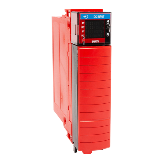
Page 21: About The Modules
Digital Safety I/O Module Operation in a Control System Chapter 1 Figure 2 below and Figure 3 on page 22 show the parts of a 1756 ControlLogix About the Modules digital safety I/O modules. Figure 2 - Example 1756-IB18S Module DC INPUT DC INPUT 8 9 10 11 12 13 14 15... - Page 22 Chapter 1 Digital Safety I/O Module Operation in a Control System Figure 3 - Example 1756-OBV8S DC OUTPUT DC OUTPUT 0 1 2 3 4 5 6 7 0 1 2 3 4 5 6 7 0 1 2 3 4 5 6 7 0 1 2 3 4 5 6 7 SAFETY SAFETY...
-
Page 23: Local I/O Modules Or Remote I/O Modules
Digital Safety I/O Module Operation in a Control System Chapter 1 You can use 1756 ControlLogix digital safety I/O modules as local or remote Local I/O Modules or I/O modules, with some restrictions that are based on the module and controller Remote I/O Modules type. -
Page 24: Remote I/O Modules
Chapter 1 Digital Safety I/O Module Operation in a Control System Remote I/O Modules When 1756 ControlLogix digital safety I/O modules reside in a separate location from a GuardLogix 5580 or Compact GuardLogix 5380 controller, they are remote I/O modules. Remote 1756 ControlLogix digital safety I/O modules are accessible over an EtherNet/IP network via a 1756 ControlLogix EtherNet/IP adapter. -
Page 25: Construct A System
Digital Safety I/O Module Operation in a Control System Chapter 1 Before you install and use your module, you must do the following: Construct a System • Install and ground a 1756 ControlLogix Series C chassis, and power supply. To install these products, refer to the publications listed in Additional Resources on page •... -
Page 26: Remote I/O Modules
Chapter 1 Digital Safety I/O Module Operation in a Control System Remote I/O Modules Complete the following: 1. Install a GuardLogix 5580 controller. 2. Install an EtherNet/IP network. 3. Connect the controller to the network. 4. Install a 1756 ControlLogix EtherNet/IP adapter in the remote chassis. 5. -
Page 27: Modules
Digital Safety I/O Module Operation in a Control System Chapter 1 Connections with 1756 ControlLogix Digital Safety I/O Modules During module configuration, you must define the module. Among the Module Definition parameters with 1756 ControlLogix digital I/O modules, you must choose a connection type for the module. - Page 28 Chapter 1 Digital Safety I/O Module Operation in a Control System Configured By Options Available with the 1756 ControlLogix Digital Safety I/O Modules The Configured By choice determines what data is exchanged between the owner-controller and the module. These are example Module Definition dialog boxes, and available Connection choices, for the 1756-IB16S and 1756-OBV8S safety modules.
- Page 29 Digital Safety I/O Module Operation in a Control System Chapter 1 Data Types Available with 1756 ControlLogix Digital Safety I/O Modules On the Module Definition dialog box for 1756 ControlLogix digital safety I/O modules, you must configure data type parameters. Table 4 describes the available data type choices based on module type.
-
Page 30: Requested Packet Interval
Chapter 1 Digital Safety I/O Module Operation in a Control System Requested Packet Interval The Requested Packet Interval (RPI) is a configurable parameter that defines a rate at which the owner-controller and the module exchange data. You set the RPI value during initial module configuration and can adjust it as necessary after module operation has begun. -
Page 31: Connection Over An Ethernet/Ip Network
Digital Safety I/O Module Operation in a Control System Chapter 1 Connection Over an EtherNet/IP Network When you configure a remote safety module, you must configure the Connection over EtherNet/IP parameter in the configuration for the remote adapter that connects the I/O modules to the network. The configuration choice dictates how input data is transmitted over the network. -
Page 32: Remote 1756 Controllogix Digital Safety Input Modules
Chapter 1 Digital Safety I/O Module Operation in a Control System Remote 1756 ControlLogix Digital Safety Input Modules Remote digital safety input modules broadcast their input data to the backplane at the time that is defined in the RPI. The input data consists of channel and status data. -
Page 33: Local Safety Output Modules
Digital Safety I/O Module Operation in a Control System Chapter 1 Local Safety Output Modules Local safety output modules receive output data from a controller and send data to the controller. The data exchange occurs over the system backplane. Controller to Local Output Module Data Transmission The controller broadcasts data to its local backplane at the RPI. - Page 34 Chapter 1 Digital Safety I/O Module Operation in a Control System These events occur when the controller sends data to a digital safety output module. 1. Data is sent in one of the following ways: • If the controller is directly connected to the EtherNet/IP network, it broadcasts data to the network.
-
Page 35: External Means
Digital Safety I/O Module Operation in a Control System Chapter 1 Any controller in the system can listen to the data from an I/O module. An External Means owner-controller, as described in Ownership on page 24, exchanges data with I/O modules. Controllers that do not own a module but must listen to data from it use the following on the Module Definition dialog box: •... -
Page 36: Protected Operations
Chapter 1 Digital Safety I/O Module Operation in a Control System To maintain the secure operation of your safety I/O modules, operations that can Protected Operations disrupt module operation are restricted based on the module operating mode. Table 5 describes the restrictions. Table 5 - Protected Operations on safety I/O modules Activity Firmware... - Page 37 Chapter Features Common to 1756 ControlLogix Digital Safety I/O Modules Topic Page Input Module Compatibility Output Module Compatibility Software Configurable Module Data Quality Reporting Fault and Status Reporting Module Inhibiting Electronic Keying Module Firmware Producer/Consumer Communication This chapter describes features that are common to 1756 ControlLogix® Digital Safety I/O Modules modules unless otherwise noted.
-
Page 38: Input Module Compatibility
Chapter 2 Features Common to 1756 ControlLogix Digital Safety I/O Modules Digital safety input modules interface to sensing devices and detect whether they Input Module Compatibility are On or Off. These input modules convert DC On/Off signals from user devices to appropriate logic level for use in the controller. -
Page 39: Software Configurable
Features Common to 1756 ControlLogix Digital Safety I/O Modules Chapter 2 You use the Studio 5000 Logix Designer® application to configure the module, Software Configurable monitor system operation, and troubleshoot issues. You can also use the Logix Designer application to retrieve this information from any module in the system: •... -
Page 40: Module Data Quality Reporting
Chapter 2 Features Common to 1756 ControlLogix Digital Safety I/O Modules The digital safety I/O modules indicate the quality of channel data that is Module Data returned to the owner-controller. Data quality represents accuracy. Levels of data Quality Reporting quality are reported via module input tags. These input tags indicate the level of data quality. -
Page 41: Fault And Status Reporting
Features Common to 1756 ControlLogix Digital Safety I/O Modules Chapter 2 The digital safety I/O modules report fault and status data along with channel Fault and Status Reporting data. Fault and status data is reported in these ways: • Logix Designer application •... - Page 42 Chapter 2 Features Common to 1756 ControlLogix Digital Safety I/O Modules In this case, you can inhibit the module and the connection to the module does not exist. IMPORTANT Whenever you inhibit an output module that is ProgMode enabled, it enters Program mode, and all outputs change to the state configured for Program mode.
-
Page 43: Electronic Keying
Features Common to 1756 ControlLogix Digital Safety I/O Modules Chapter 2 Electronic Keying reduces the possibility that you use the wrong device in a Electronic Keying control system. It compares the device that is defined in your project to the installed device. -
Page 44: Module Firmware
Chapter 2 Features Common to 1756 ControlLogix Digital Safety I/O Modules The digital safety I/O modules are manufactured with module firmware Module Firmware installed. If updated module firmware revisions are available in the future, you can update the firmware. If the module is configured for Exact Match, the controller checks to make sure that the module has the correct firmware revision. -
Page 45: Overview
Chapter 1756-IB16S Input Module Features Topic Page Overview Safety Application Suitability Level Use Test Output with a Safety Input Single-channel Point Operation Type Safety Input Fault Reset Safety Input Delay Time Data Transfer at RPI Module Health Diagnostic Fault and Status Reporting Field Power Loss Detection Short Circuit Protection This section describes features that are available on the 1756-IB16S module. -
Page 46: Safety Application Suitability Level
Chapter 3 1756-IB16S Input Module Features The following apply to the test outputs: • Test outputs can be configured as: – Not Used – Power Supply – Pulse Test • Separate test outputs are provided for short circuit detection of a safety input (or inputs). -
Page 47: Use Test Output With A Safety Input
1756-IB16S Input Module Features Chapter 3 A test output can be used in combination with a safety input for short circuit and Use Test Output with a cross-channel fault detection. In this case, Point Mode must be Safety Pulse Test. Safety Input Safety input pairs must be associated with different Test Output sources. - Page 48 Chapter 3 1756-IB16S Input Module Features Figure 7 - 1756-IB16S Test Pulse in a Cycle On the 1756-IB16S module, the test pulse width (X) is less than 600 µs; the test pulse period (Y) is less than 100 ms. When the external input contact is closed, a test pulse is output from the test output terminal to diagnose the field wiring and input circuitry.
-
Page 49: Single-Channel Point Operation Type
1756-IB16S Input Module Features Chapter 3 If an error is detected on the input channel, Safety Input Data and Safety Input Single-channel Point Status turn off. Operation Type For information on how using single-channel Point Operation Type with a 1756-IB16S module affects the safety application suitability level, see Table 6 on page Figure 9 - Normal Operation and Fault Detection (Not to Scale) -
Page 50: Safety Input Fault Reset
Chapter 3 1756-IB16S Input Module Features The I/O channel supports a module-level user-configurable 'Latch Fault until Safety Input Fault Reset reset via output tag' mode and recovers from these faults: • Field Power Off Detection • Safety Input Short Circuit 'Latch Fault until reset via output tag' mode is Enabled When Latch Fault... -
Page 51: Off To On Delay
1756-IB16S Input Module Features Chapter 3 Off to On Delay An input signal is treated as Logic 0 during the Off to On delay time after the rising edge of the input contact. The input turns on only if the input contact remains on after the Off to On delay time has elapsed. -
Page 52: On To Off Delay
Chapter 3 1756-IB16S Input Module Features On to Off Delay An input signal is treated as Logic 1 during the On to Off delay time after the falling edge of the input contact. The input turns off only if the input contact remains off after the On to Off delay time has elapsed. -
Page 53: Point Diagnostics
1756-IB16S Input Module Features Chapter 3 Point diagnostics provide information on an individual point basis. For example, Point Diagnostics you can check individual input points and test output points on a 1756-IB16S safety input module for the presence of a Short Circuit condition. Figure 12 shows how to access output point diagnostics on the 1756-IB16S module and the diagnostics dialog box. -
Page 54: Fault And Status Reporting
Chapter 3 1756-IB16S Input Module Features The input modules send fault and status data with channel data to the owner and Fault and Status Reporting listening controllers. The data is returned via module tags that you can monitor in your Logix Designer application. With some exceptions, the digital input modules provide the fault and data status in a point-centric format. -
Page 55: Field Power Loss Detection
1756-IB16S Input Module Features Chapter 3 The Field Power Loss Detection feature monitors for the loss of field-side power. Field Power Loss Detection When power is lost, the module detects the loss of field power and faults. As a result, fault data is sent to the controller. Keep in mind that all points on the module fault when a field power is lost. -
Page 56: Short Circuit Protection
Chapter 3 1756-IB16S Input Module Features Short Circuit Protection helps to prevent damage to a test output that can result Short Circuit Protection when more current is present at the output than it can handle. The diagnostic is supported on all module outputs. Table 10 describes what happens when a short circuit condition is detected. -
Page 57: Chapter 4, 1756-Obv8S Output Module Features
Chapter 1756-OBV8S Output Module Features Topic Page Overview Safety Application Suitability Level Safety Output with Test Pulse Single-channel Point Operation Type Dual-channel Point Operation Type Safety Output Fault Reset Fault and Status Reporting Module Health Diagnostics Field Power Loss Detection No Load Detection Short Circuit Protection Thermal Shutoff... -
Page 58: Overview
Chapter 4 1756-OBV8S Output Module Features The 1756-OBV8S is a safety output module that uses eight safety outputs. You Overview use the outputs in one of the following ways: • Sourcing/sinking outputs in Bipolar Output mode • Sourcing outputs in Sourcing Output mode. •... -
Page 59: Safety Application Suitability Level
1756-OBV8S Output Module Features Chapter 4 Table 13 describes the safety application suitability levels for the 1756-OBV8S Safety Application module. Suitability Level Table 13 - Safety Application Suitability for 1756-OBV8S Module Suitability Level Conditions Notes Safety applications that are rated up to, and The safety function uses single -channel Consider the following: including, SIL CL3, PLd, Cat. -
Page 60: Safety Output With Test Pulse
Chapter 4 1756-OBV8S Output Module Features When the safety output is on, the safety output can be configured to pulse test Safety Output with Test the safety output channel. By using this function, you can continuously test the Pulse ability of the safety output to remove power from the output terminals of the module. -
Page 61: Single-Channel Point Operation Type
1756-OBV8S Output Module Features Chapter 4 When the output channel is in the On state and without any faults, the safety Single-channel Point outputs turned on. The status is normal. If a fault is detected on the output Operation Type channel, the safety output data and individual safety output status turn off. -
Page 62: Dual-Channel Point Operation Type
Chapter 4 1756-OBV8S Output Module Features When dual-channel Point Operation Type is used, output channels function as Dual-channel Point connection pairs. Connection pairs are as follows: Operation Type • Channels 0 and 1 • Channels 2 and 3 • Channels 4 and 5 •... -
Page 63: Safety Output Fault Reset
1756-OBV8S Output Module Features Chapter 4 The I/O channel supports a module-level user-configurable ‘Latch Fault until Safety Output Fault Reset reset via output tag’ mode and recovers from only these field faults: • Field Power Off Detection • Safety Output ShortCircuitGround •... -
Page 64: Fault And Status Reporting
Chapter 4 1756-OBV8S Output Module Features The 1756-OBV8S module multicasts fault and status data with channel data to Fault and Status Reporting the owner and listening controllers. The data is returned via module tags that you can monitor in your Logix Designer application. For more information on how to use module tags to monitor fault and status reporting, see Table 24 on page 71... -
Page 65: Point Diagnostics
1756-OBV8S Output Module Features Chapter 4 Point diagnostics provide information on an individual point basis. For example, Point Diagnostics you can check individual points on a 1756-OBV8S safety output module for the presence of a Short Circuit condition. To access output point diagnostics on the 1756-OBV8S module, click the Diagnostics button for the point. -
Page 66: Field Power Loss Detection
Chapter 4 1756-OBV8S Output Module Features The Field Power Loss Detection feature monitors for the loss of field power. Field Power Loss Detection IMPORTANT The 1756-OBV8S module supports Field Power Loss Detection. The module receives field-side power via the DC power terminals on the module. -
Page 67: No Load Detection
1756-OBV8S Output Module Features Chapter 4 No Load Detection detects when a wire is disconnected from the output, or a No Load Detection missing load for each output point in the Off state. No Load Detection is enabled by default on the 1756-OBV8S modules. You cannot configure it. -
Page 68: Short Circuit Protection
Chapter 4 1756-OBV8S Output Module Features Short Circuit Protection helps to prevent damage to the output that can result Short Circuit Protection when more current is present at the output than it can handle. Table 18 describes what happens when a short circuit condition is detected on a 1756-OBV8S module. -
Page 69: Other Conditions That Can Trigger The Short Circuit Diagnostic On The 1756-Obv8S Module
1756-OBV8S Output Module Features Chapter 4 Other Conditions That Can Trigger the Short Circuit Diagnostic on the 1756-OBV8S Module Table 20 describes conditions that can trigger the Short Circuit diagnostic. Table 20 - Conditions That Trigger Short Circuit Diagnostic Conditions Output Behavior Tag and Diagnostic Combinations I/O Status Indicator State... -
Page 70: Ground Condition
Chapter 4 1756-OBV8S Output Module Features Output Recovery After Overload or Short Circuit to Ground Condition describes test output recovery after overload or short circuit to ground Table 21 conditions occur. Table 21 - Output Recovery - 1756-OBV8S Module Cause of Fault Module Operating Conditions Correction Recovery Time... -
Page 71: Fault And Status Reporting
1756-OBV8S Output Module Features Chapter 4 The output modules multicast fault and status data with channel data to the Fault and Status Reporting owner and listening controllers. The data is returned via module tags that you can monitor in your Logix Designer application. Table 24 lists tags that are used on the 1756-OBV8S module. -
Page 72: Connection Fault Handling
Chapter 4 1756-OBV8S Output Module Features You can configure module behavior when a connection fault occurs, that is, the Connection Fault Handling connection between the owner-controller and the output module breaks. You must define the immediate output behavior when the connection breaks. Output Behavior Immediately After a Connection Fault ATTENTION: If you change the Output state from OFF to HOLD during Program or Communication Fault modes, make sure this does not create an unsafe state... -
Page 73: Forcing
1756-OBV8S Output Module Features Chapter 4 Use a force to override data that your logic either uses or produces. Forcing IMPORTANT When a safety signature exists, forcing safety I/O is not permitted in the safety portion of the application. • Test and debug your logic. •... -
Page 74: Disable Or Remove A Force
Chapter 4 1756-OBV8S Output Module Features Disable or Remove a Force To stop the effect of a force and let your project execute as programmed, disable or remove the force. • You can disable or remove I/O and SFC forces simultaneously or separately. -
Page 75: Gsv Instruction
1756-OBV8S Output Module Features Chapter 4 GSV Instruction This example shows how to use a GSV instruction to get the status of forces. For the purposes of this example, Force_Status is a DINT tag. To determine this Examine this bit For this value Forces are installed. - Page 76 Chapter 4 1756-OBV8S Output Module Features Notes: Rockwell Automation Publication 1756-UM013B-EN-P - October 2019...
-
Page 77: Configure And Replace Safety Modules
Chapter Configure and Replace Safety Modules Topic Page Create a New Module Edit the Module Configuration Common Categories Edit the 1756-IB16S Module Configuration Categories Edit the 1756-OBV8S Module Points Category View the Module Tags Replace a Safety Module This chapter describes how to configure your 1756 ControlLogix® Digital Safety I/O Modules in a Studio 5000 Logix Designer®... -
Page 78: Create A New Module
Chapter 5 Configure and Replace Safety Modules The project must be offline to add safety modules to it. Create a New Module You can create a new local or remote safety module. Local I/O modules are installed in the same system as the GuardLogix® 5580 controllers. Remote I/O modules are installed in a system that includes a 1756 ControlLogix EtherNet/IP™... - Page 79 Configure and Replace Safety Modules Chapter 5 3. At the Select Module Type window, click Create to add the discovered module to your project. 4. At the New Module window, configure the module properties and click OK. Follow the same steps to add additional local I/O modules. Rockwell Automation Publication 1756-UM013B-EN-P - October 2019...
-
Page 80: New Remote I/O Module
Chapter 5 Configure and Replace Safety Modules New Remote I/O Module To create a new remote safety I/O module, complete these steps. 1. Add a ControlLogix EtherNet/IP adapter to the project. 2. Right-click the EtherNet/IP adapter and choose New Module. 3. - Page 81 Configure and Replace Safety Modules Chapter 5 4. You can click OK to use the default configuration as shown or edit the module configuration. The rest of this chapter describes how to edit module configuration categories. Follow the same steps to add additional remote I/O modules. Rockwell Automation Publication 1756-UM013B-EN-P - October 2019...
-
Page 82: Edit The Module Configuration Common Categories
Chapter 5 Configure and Replace Safety Modules You click the category names in the New Module dialog box to view and change Edit the Module the configuration parameters. Before you edit the module configuration, Configuration Common consider the following: Categories •... -
Page 83: General Category
Configure and Replace Safety Modules Chapter 5 General Category The General category appears first when you create a module. The parameters in this category are the same for all 1756 ControlLogix digital safety I/O modules. You use this category to complete the following tasks: •... - Page 84 Chapter 5 Configure and Replace Safety Modules Module Definition Module Definition parameters are available on the General tab of the Module Properties dialog box in the Logix Designer application project. Table 25 describes the parameters on the Module Definition dialog box. 1756-IB16S 1756-OBV8S Table 25...
-
Page 85: Connection Category
Configure and Replace Safety Modules Chapter 5 Connection Category The Connection category lets you inhibit the module. Before you inhibit the module, make sure that you are aware of the impact it has on your application. For more information on inhibiting the module, see page IMPORTANT You cannot set the Requested Packet Interval (RPI) for the safety modules on the Connections category. -
Page 86: Safety Category
Chapter 5 Configure and Replace Safety Modules Safety Category The Safety category lets you set the RPI rate. You must click the Advanced button to change the Connection Reaction Time Limit configuration. IMPORTANT Remember, the Safety Task period determines the 1756-OBV8S module RPI. For more information on the RPI and the Connection Reaction Time Limit parameters, see Requested Packet Interval on page... -
Page 87: Module Info Category
Configure and Replace Safety Modules Chapter 5 Module Info Category The Module Info category displays module and status information about the module when the project is online. You can use this category to complete the following: • Determine the identity of the module. •... -
Page 88: Edit The 1756-Ib16S Module Configuration Categories
Chapter 5 Configure and Replace Safety Modules These categories are available when you configure a 1756-IB16S module: Edit the 1756-IB16S Module • Input Points Category Configuration Categories • Test Output Points Category Input Points Category The Input Points category is only available if you choose This Controller for the Configured By parameter on the Module Definition dialog box. -
Page 89: Test Output Points Category
Configure and Replace Safety Modules Chapter 5 Test Output Points Category The Test Output Points category is only available if you choose This Controller for the Configured By parameter on the Module Definition dialog box. You must configure each point to use it in a Safety application. The outputs are disabled by default. -
Page 90: Edit The 1756-Obv8S Module Points Category
Chapter 5 Configure and Replace Safety Modules To use the Points category, on the Module Definition dialog box choose Edit the 1756-OBV8S Configured By > This Controller. Module Points Category The outputs are disabled by default. To use an output in a Safety application, you must configure the Point Operation Type and Point Mode. -
Page 91: Point Mode
Configure and Replace Safety Modules Chapter 5 Point Operation Type Single When the output channel is in the On state and without any faults, the safety outputs turned on. The status is normal. If a fault is detected on the output channel, the safety output data and individual safety output status turn off. -
Page 92: View The Module Tags
Chapter 5 Configure and Replace Safety Modules When you create a module, the Logix Designer application creates a set of tags View the Module Tags that you can view in the Tag Editor. Each configured feature on your module has a distinct tag that is available for use in the controller program logic. -
Page 93: Replace A Safety Module
Configure and Replace Safety Modules Chapter 5 Replacing a safety module that sits on a CIP Safety™ network is more complicated Replace a Safety Module than replacing standard devices because of the Safety Network Number (SNN). Safety devices require this more complex identifier to make sure that module numbers that are duplicated on separate subnets across all of the networks in the application do not compromise communication between the correct safety devices. - Page 94 Chapter 5 Configure and Replace Safety Modules Follow these steps to reset the module to its out-of-box configuration when online. 1. Right-click the module and choose Properties. 2. On the Safety tab, click Reset Ownership. 3. When a dialog box appears asking if you want to continue with the reset, read it and click Yes.
-
Page 95: Replace A Module In A Logix 5000 System
Configure and Replace Safety Modules Chapter 5 Replace a Module in a Logix 5000 System Consider the following conditions before you replace a safety module in a Logix 5000™ system: • If you rely on a portion of the CIP Safety system to maintain SIL 3 behavior during module replacement and functional testing, you must use the Configure Only When No Safety Signature Exists feature. - Page 96 Chapter 5 Configure and Replace Safety Modules Scenario 1 - Replacement Device is Out-of-box and Safety Signature Exists 1. Remove the old I/O device and install the new device. 2. Right-click the replacement safety I/O device and choose Properties. 3. On the General category, click to the right of the safety network number to open the Safety Network Number dialog box.
- Page 97 Configure and Replace Safety Modules Chapter 5 5. Click Yes on the confirmation dialog box to set the SNN and accept the replacement device. 6. Follow your company-prescribed procedures to functionally test the replaced I/O device and system and to authorize the system for use. Rockwell Automation Publication 1756-UM013B-EN-P - October 2019...
- Page 98 Chapter 5 Configure and Replace Safety Modules Scenario 2 - Replacement Device SNN is Different from Original and Safety Signature Exists 1. Remove the old I/O device and install the new device. 2. Right-click your safety I/O device and choose Properties. 3.
- Page 99 Configure and Replace Safety Modules Chapter 5 7. The Configuration Ownership now shows Not Owned. 8. Click the module General category. 9. Click to the right of the safety network number to open the Safety Network Number dialog box. Rockwell Automation Publication 1756-UM013B-EN-P - October 2019...
- Page 100 Chapter 5 Configure and Replace Safety Modules 10. Click Set. 11. Click Yes on the confirmation dialog box to set the SNN and accept the replacement device. 12. Follow your company-prescribed procedures to functionally test the replaced I/O device and system and to authorize the system for use. Rockwell Automation Publication 1756-UM013B-EN-P - October 2019...
- Page 101 Configure and Replace Safety Modules Chapter 5 Scenario 3 - Replacement Device SNN is Different from Original and No Safety Signature Exists 1. Remove the old I/O device and install the new device. 2. Right-click your safety I/O device and choose Properties. 3.
- Page 102 Chapter 5 Configure and Replace Safety Modules Replacement with ‘Configured Always’ Enabled ATTENTION: Enable the ‘Configure Always’ feature only if the entire CIP Safety Control System is not being relied on to maintain SIL 3 behavior during the replacement and functional testing of a module. Do not place modules that are in the out-of-box condition on a CIP Safety network when the Configure Always feature is enabled, except while following this replacement procedure.
-
Page 103: Module Status Indicators
Appendix Troubleshoot Your Module Topic Page Module Status Indicators Use the Logix Designer Application for Troubleshooting You can use the module status indicators and the Studio 5000 Logix Designer® application to troubleshoot the I/O modules. 1756 ControlLogix® digital safety I/O modules use these status indicators: Module Status Indicators DC OUTPUT DC INPUT... -
Page 104: Ok Status Indicators
Appendix A Troubleshoot Your Module OK Status Indicators The OK status indicator shows the module status. Table 1 - Module OK Status Indicator Indicator State Description There is no module power applied. Green The device is operating in a normal condition. At least one IO connection is in the established state. -
Page 105: Use The Logix Designer Application For Troubleshooting
Troubleshoot Your Module Appendix A The Logix Designer application indicates the presence of fault conditions. Use the Logix Designer Application for Fault conditions are reported in the following ways: Troubleshooting • Warning Signal in the I/O Configuration Tree • Status and Fault Information in Module Properties Categories •... -
Page 106: Status And Fault Information In Module Properties
Appendix A Troubleshoot Your Module Status and Fault Information in Module Properties Categories The Module Properties section in the Logix Designer application includes a series of categories. The numbers and types of categories varies by module type. Each category includes options to configure the module or monitor the status of the module. - Page 107 Troubleshoot Your Module Appendix A Module Fault Descriptions on Connection Category As shown in Figure 3, a module fault description that includes an error code that is associated with the specific fault type is listed on the Connection category. Figure 3 - Fault Description with Error Code Module Fault Descriptions on Module Info Category As shown in Figure...
-
Page 108: Module And Point Diagnostics
Appendix A Troubleshoot Your Module Module and Point Diagnostics You can use diagnostics in a Logix Designer application project to monitor module and/or point operating conditions and to troubleshoot issues that affect a module and/or point. Diagnostics when the project is online. •... - Page 109 Troubleshoot Your Module Appendix A Point Diagnostics Point diagnostics provide information on an individual point basis. For example, you can check individual points on a 1756-IB16S safety input module for the presence of a Short Circuit condition. Remember the following: •...
-
Page 110: Logix Designer Application Tag Editor
Appendix A Troubleshoot Your Module Logix Designer Application Tag Editor Figure 7 show how fault conditions are indicated in the controller tags. Figure 7 - Fault Indication in Controller Tags Rockwell Automation Publication 1756-UM013B-EN-P - October 2019... -
Page 111: Internalfault Triggered On The Safety Output Module
Troubleshoot Your Module Appendix A Table 3 describes conditions that can trigger InternalFault. InternalFault Triggered on the Safety Output Module Table 3 - Conditions That Trigger InternalFault Conditions Output Tag Value Diagnostic Value I/O Status Behavior Indicator State • Output Mode - BIpolar Faults I.Ptxx.Fault tag = 1 InternalFault = 1... - Page 112 Appendix A Troubleshoot Your Module Notes: Rockwell Automation Publication 1756-UM013B-EN-P - October 2019...
- Page 113 Appendix Module Tag Definitions Topic Page Access the Tags Access the Tags 1756-IB16S Module Tags 1756-OBV8S Module Tags Module tags are created when you add a module to the Studio 5000 Logix Designer® application project. The set of tags that are associated with any module depends on the choices that you make in the Module Definition dialog box.
-
Page 114: Access The Tags
Appendix B Module Tag Definitions You can view tags from the Tag Editor. Access the Tags 1. Open your Logix Designer application project. 2. Right-click Controller Tags and choose Monitor Tags. 3. Open the tags as necessary to view specific tags. The module tags use defined naming conventions. -
Page 115: 1756-Ib16S Module Tags
Module Tag Definitions Appendix B This section describes the tags that are associated with the 1756-IB16S module. 1756-IB16S Module Tags Input Tags Table 4 describes the 1756-IB16S module input tags. Table 4 - 1756-IB16S Module Input Tags Name Data Type Definition Valid Values Available With These Input... -
Page 116: Output Tags
Appendix B Module Tag Definitions Table 4 - 1756-IB16S Module Input Tags Name Data Type Definition Valid Values Available With These Input Data Type Choices Ptxx.ShortCircuit BOOL Indicates a short circuit. • 0 = No short circuit Safety Data • 1 = Short circuit Ptxx.Status BOOL Indicates the status of the channel. -
Page 117: 1756-Obv8S Module Tags
Module Tag Definitions Appendix B This section describes the tags that are associated with the 1756-OBV8S module. 1756-OBV8S Module Tags Input Tags Table 6 describes the 1756-OBV8S module input tags. Table 6 - 1756-OBV8S Module Input Tags Name Data Type Definition Valid Values Available With These... -
Page 118: Output Tags
Appendix B Module Tag Definitions Table 6 - 1756-OBV8S Module Input Tags Name Data Type Definition Valid Values Available With These Input Data Type Choices Ptxx.FieldPowerOff BOOL Indicates that a field power loss condition exists on • 0 = No field power off condition Safety Data the channel. -
Page 119: Before You Begin
Appendix Application and Wiring Examples for Safety Modules Topic Page 1756-IB16S Module Wiring Diagrams 1756-OBV8S Module Wiring Diagrams This appendix provides example wiring diagrams for the 1756 ControlLogix® safety I/O modules that can be used in functional safety applications. The wiring configuration affects the safety application level to which a 1756 ControlLogix I/O safety module is suitable. -
Page 120: 1756-Ib16S Module Wiring Diagrams
Appendix C Application and Wiring Examples for Safety Modules You must connect a 24V DC SELV/PELV power source to the DC+/- terminals 1756-IB16S Module to provide field-side power. Wiring Diagrams IMPORTANT • The 24V (DC+ and DC-) power connections are used to supply field-side power to the module. - Page 121 Application and Wiring Examples for Safety Modules Appendix C When the module is wired as shown, it is suitable for applications that are rated up to, and including, Category 3 and PLd as defined in ISO 13849-1. IMPORTANT Switches are suitable for applications that are IN-0 TO-0 rated up to, and including SIL 3 CL3, PLe, Cat 3.
- Page 122 Appendix C Application and Wiring Examples for Safety Modules When the module is wired as shown, it is suitable for applications that are rated up to, and including, Category 4 and PLe as defined in ISO 13849-1. To achieve that suitability rating, you may have to perform diagnostic testing of the safety function.
-
Page 123: 1756-Obv8S Module Wiring Diagrams
Application and Wiring Examples for Safety Modules Appendix C You can use the 1756-OBV8S module in Bipolar mode or Sourcing mode. 1756-OBV8S Module Wiring Diagrams IMPORTANT • The 24V (DC+ and DC-) power connections are used to supply field-side power to the module. - Page 124 Appendix C Application and Wiring Examples for Safety Modules When the module is wired as shown, it is suitable for applications that are rated up to, and including, Category 4 and PLe as defined in ISO 13849-1. To achieve that suitability rating, you may have to perform diagnostic testing and monitoring of the safety function.
- Page 125 Application and Wiring Examples for Safety Modules Appendix C When the module is wired as shown, it is suitable for applications that are rated up to, and including, Category 4 and PLe as defined in ISO 13849-1. To achieve that suitability rating, you may have to perform diagnostic testing and monitoring of the safety function.
-
Page 126: Sourcing Mode
Appendix C Application and Wiring Examples for Safety Modules Sourcing Mode When the module is wired as shown, it is suitable for applications that are rated up to, and including, Category 2 and PLd as defined in ISO 13849-1. To achieve that suitability rating, you may have to perform diagnostic testing and monitoring of the safety function. - Page 127 Application and Wiring Examples for Safety Modules Appendix C When the module is wired as shown, it is suitable for applications that are rated up to, and including, Category 4 and PLe as defined in ISO 13849-1. To achieve that suitability rating, you may have to perform diagnostic testing and monitoring of the safety function.
- Page 128 Appendix C Application and Wiring Examples for Safety Modules Notes: Rockwell Automation Publication 1756-UM013B-EN-P - October 2019...
- Page 129 Appendix Safety Data for Safety Modules This appendix lists calculated values for probability of a dangerous failure on demand (PFD), average frequency of a dangerous failure per hour (PFH), and mean time to failure (MTTF). PFD and PFH calculations comply with IEC61508, edition 2, 2010.
-
Page 130: 1756-Ib16S Safety Data
Appendix D Safety Data for Safety Modules Table 8 lists the safety data for the 1756-IB16S module. 1756-IB16S Safety Data Table 8 - 1756-IB16S Module Safety Parameter Data Point Operation Type Single Channel Dual Channel (at controller instruction Attribute level) Safety Function Architecture (HFT) Safe Failure Rate (λ... -
Page 131: 1756-Obv8S Safety Data
Safety Data for Safety Modules Appendix D Table 9 lists the safety data for the 1756-OBV8S module. 1756-OBV8S Safety Data Table 9 - 1756-OBV8S Module Safety Data Output Mode Sourcing Bipolar Point Operation Type Point Operation Type Attribute Single Dual Single Safety Function Architecture (HFT) Safe Failure Rate (λ... - Page 132 Appendix D Safety Data for Safety Modules Notes: Rockwell Automation Publication 1756-UM013B-EN-P - October 2019...
-
Page 133: Index
Index Logix Designer application 39 configuration overview 26 configuration connection types 28 reset safety modules to out-of-box module definition configuration 93 safety modules 84 configure module tag definition 113 with Logix Designer application 39 name module tags 114 connection 7 replace a safety module 93 reset safety modules to out-of-box connection category... - Page 134 Index remote I/O modules 24 removable terminal block 10 replace a safety module 93 reset safety modules to out-of-box configuration 93 valid value 30 RTB. See removable terminal block safety category 1756-IB16S and 1756-OBV8S modules 86 safety network number 8 short circuit protection digital output modules 68 safety input modules 56...
- Page 136 Rockwell Automation maintains current product environmental information on its website at http://www.rockwellautomation.com/rockwellautomation/about-us/sustainability-ethics/product-environmental-compliance.page. Allen-Bradley, Compact 5000, ControlLogix, GuardLogix, Kinetix, Logix 5000, PanelView, PowerFlex, RSNetWorx, Rockwell Automation, Rockwell Software, Safety Automation Builder, Stratix, and Studio 5000 Logix Designer are trademarks of Rockwell Automation, Inc.
Need help?
Do you have a question about the 1756 Series and is the answer not in the manual?
Questions and answers