urmet domus 1761/31 Installer Manual
Ip 7” video door phone
Hide thumbs
Also See for 1761/31:
- Manual (68 pages) ,
- Installation handbook (29 pages) ,
- Quick manual (4 pages)
Table of Contents
Advertisement
Available languages
Available languages
Quick Links
Mod.
1761
DS 1761-015
LBT 20969
ooooooo
Interactive Links
VIDEOCITOFONO IP 7''
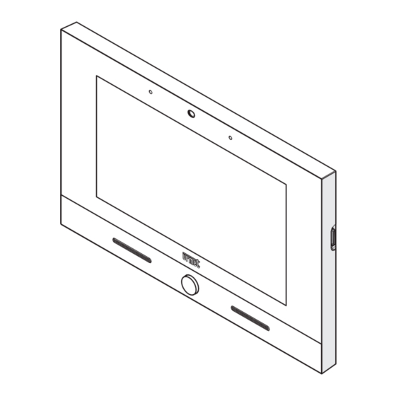
IP 7" VIDEO DOOR PHONE
7" IP-BEELDINTERCOM
Sch./Ref. 1761/31 (Bianco / White / Wit)
Sch./Ref. 1761/33 (Nero / Black / Zwart)
LIBRETTO INSTALLATORE RELATIVO ALLA DOMOTICA YOKIS
INSTALLER BOOKLET FOR THE YOKIS HOME AUTOMATION
INSTALLATIEHANDLEIDING VOOR HET GEDEELTE
HUISAUTOMATISERING
Advertisement
Chapters
Table of Contents

Related Manuals for urmet domus 1761/31


Summary of Contents for urmet domus 1761/31
- Page 1 Interactive Links VIDEOCITOFONO IP 7’’ IP 7” VIDEO DOOR PHONE 7” IP-BEELDINTERCOM Sch./Ref. 1761/31 (Bianco / White / Wit) Sch./Ref. 1761/33 (Nero / Black / Zwart) LIBRETTO INSTALLATORE RELATIVO ALLA DOMOTICA YOKIS INSTALLER BOOKLET FOR THE YOKIS HOME AUTOMATION INSTALLATIEHANDLEIDING VOOR HET GEDEELTE...
-
Page 2: Table Of Contents
Le prestazioni descritte nel seguente libretto fanno riferimento alla versione firmware 2.1.0_49_VER_7_8_0_ R7 del Videocitofono IP 1761/31 e /33. Interactive Links Nel documento sono presenti LINK INTERATTIVI per rendere la consultazione più rapida ed efficiente. ITALIANO SOMMARIO 1 CONFIGURAZIONE PULSANTI ......................3... -
Page 3: Configurazione Pulsanti
CONFIGURAZIONE PULSANTI L’utente finale avrà la possibilità di utilizzare fino ad un massimo di 12 pulsanti virtuali per comandare singoli punti di uscita oppure scenari: Questi pulsanti si distinguono in 2 gruppi: i primi 8 (Pulsanti Yokis) e gli ultimi 4 (Pulsanti Compositi). I Pulsanti Yokis Sono i primi 8 e sono in tutto e per tutto equivalenti agli 8 pulsanti di un telecomando Yokis modello TLC8CP. -
Page 4: Configurazione Diretta Dei Pulsanti Yokis
1.1.1 Configurazione Diretta dei Pulsanti Yokis Ogni Pulsante Yokis può essere configurato per comandare un singolo modulo di attuazione o più moduli (Scenario o Scenario di Centralizzazione), in Modalità Diretta o in Modalità Bus Radio. Si rimanda alla lettura del ‘Promemoria Radio’ Yokis per maggiori informazioni sulle possibilità a disposizione. - Page 5 Toccare il pulsante Yokis che si desidera configurare. Compare una videata dove è possibile impostare: — il NOME del pulsante (che vedrà poi l’utente), — l’ICONA del pulsante (che vedrà l’utente). Fatto ciò, toccare il pulsante ‘CONFIGURA’: comparirà la videata seguente, da cui è possibile fare le stesse configurazioni che normalmente possono essere fatte su di un pulsante di un telecomando Yokis: DS1761-015...
- Page 6 Prima di descrivere i singoli comandi nel dettaglio è bene dare qualche indicazione generale. Innanzitutto, toccando in alto a destra, compare un QR code: Il QR code può essere usato per accedere al manuale di configurazione ed ottenere così aiuto. La configurazione dei pulsanti è...
- Page 7 CREA CONNESSIONE Apre un sotto-menu orientato al ‘collegamento’ del pulsante ad uno o più ricevitori. Connetti (o disconnetti) E5 R1 Consente di ‘collegare’ logicamente il pulsante ad un ricevitore. In Modalità diretta si possono collegare uno o più ricevitori, fino ad un massimo di 4 (se si collega un quinto ricevitore, questo sostituirà...
- Page 8 REGOLA MODALITÀ E CENTRALIZZAZIONE DI LUCI O TAPPARELLE Per default i pulsanti Yokis funzionano in ‘Modalità diretta’. Comandando fino ad un max. di 4 ricevitori. Su di un Videocitofono è invece spesso utile utilizzare i Pulsanti in modalità Centralizzata: avere ad esempio un pulsante che chiude tutte le tapparelle, un altro che spegne tutte le luci, etc.
- Page 9 REGOLA FUNZIONE È infine possibile definire, per il pulsante, la modalità di funzionamento, tra le 4 possibili: - Commutazione (luci), Variazione/Spegnimento (dimmer), Salita/Arresto/Discesa (tapparella) - Accensione (luci), Salita&Arresto (tapparella) - Spegnimento (luci), Discesa&Arresto (tapparella) - Richiamo Memoria, Vai a posizione intermedia (tapparella) Il riferimento è...
-
Page 10: Configurazione Pulsanti Yokis Tramite Telecomando
— Inviare 23 ( E 23 ) per sbloccare la configurazione del modulo e attendere 3 lampeggi sul ricevitore. — Inviare 27 ( E 27 ) per commutare il modulo alla modalità timer e attendere 7 lampeggi sul ricevitore. — Inviare 26 ( E 26 ) per configurare la durata in minuti e attendere 6 lampeggi sul ricevitore. - Page 11 Inserire la Password (fissa: 1937) e confermare con ‘OK’. Si presenta la pagina seguente: Scegliere la terza voce di menu: ‘Importa i Pulsanti Yokis da un telecomando (o un altro Videocitofono)’. Partirà un Wizard che guida l’installatore al completamento della procedura di importazione: seguire le indicazioni del Wizard.
-
Page 12: Configurazione Mista Dei Pulsanti Yokis
Toccare il pulsante Yokis che si desidera configurare. Compare: L’icona in alto a destra indica che si tratta di un ‘Pulsante Importato’. È possibile impostare: — il NOME del pulsante (che vedrà poi l’utente), — l’ICONA del pulsante (che vedrà l’utente). È... - Page 13 Poi si potrebbe definire un Pulsante Composito (‘Sera’) che li richiama entrambi e consente quindi la chiusura di tutte le tapparelle e la contemporanea accensione delle sole luci di Sala e Cucina. Nel dettaglio è anche possibile definire che ‘prima’ vengano accese le luci e ‘dopo’ chiuse le tapparelle. Ed è...
- Page 14 Toccare il pulsante Composito che si desidera configurare. Compare una videata dove è possibile impostare: — il NOME del pulsante (che vedrà poi l’utente), — l’ICONA del pulsante (che vedrà l’utente). Fatto ciò, toccare il pulsante ‘CONFIGURA’: comparirà la videata seguente: DS1761-015...
- Page 15 SCEGLI I PULSANTI Consente di specificare quali Pulsanti Yokis sono ‘raggruppati’ sotto questo Pulsante Composito. Ovviamente è importante sceglierne almeno 2 per avere qualche effetto utile. RITARDO TRA I PULSANTI Consente di definire un eventuale ‘ritardo’ tra l’azionamento di un Pulsante Yokis ed il successivo, per creare degli Scenari temporizzati: DS1761-015...
- Page 16 ORDINE DEI TASTI Qui è possibile specificare se gli Azionamenti dei Pulsanti Yokis saranno eseguiti nell’ordine di default (dal primo all’ottavo) o nell’ordine inverso (dall’ottavo al primo). DS1761-015...
-
Page 17: Impaginazione Pulsanti
IMPAGINAZIONE PULSANTI I Pulsanti utilizzabili sono, complessivamente 12: 8 Yokis e 4 Compositi. Se l’utente finale non li usa tutti, è possibile ‘nascondere’ quelli non utilizzati. È inoltre possibile ‘spostare’ quelli di uso più frequente nella posizione desiderata. Dalla Pagina di Domotica Yokis, premere l’icona di Configurazione: Inserire la Password (fissa: 1937) e confermare con ‘OK’. -
Page 18: Associa Chiave Mifare
Deselezionare i Pulsanti che si intende nascondere (esempio Pulsante2). Per riposizionare un pulsante in un’altra posizione, trascinarlo con il dito nella posizione desiderata. Confermare con ‘OK’. ASSOCIA CHIAVE MIFARE Associa una chiave MIFARE ad un solo pulsante Yokis. E’ sufficiente scegliere il pulsante da associare alla chiave e, dopo aver dato conferma, passare la chiave sul lato sinistro del monitor in prossimità... -
Page 19: English
The features described in the following booklet refer to version: 2.1.0_49_VER_7_8_0_R7 of the IP 1761/31 and 1761/33 Video door phone. Interactive Links The document contains INTERACTIVE LINKS for faster and more efficient consultation. ENGLISH INDEX 1. BUTTONS CONFIGURATION ......................20 Yokis Buttons Configuration ......................20... -
Page 20: Buttons Configuration
BUTTONS CONFIGURATION The end user will be able to use up to a maximum of 12 virtual buttons to control individual outputs or scenarios: These buttons are divided in 2 groups: the first 8 (Yokis buttons) and the last 4 (Composite buttons). Yokis Buttons These are the first 8 buttons, perfectly equivalent to the 8 buttons in a Yokis remote control model TLC8CP. -
Page 21: Yokis Buttons Direct Configuration
1.1.1 Yokis Buttons Direct Configuration Each Yokis Button can be configured to control one or more activation modules (Scenario or Centralisation Scenario), either in Direct Mode or in Radio Bus Mode. Please refer to the Yokis Radio Quick Installation Guide for more information on the available options. From the Yokis Home Automation Page, press the Configuration icon: Enter the Password (fixed: 1937) and confirm with ‘OK’. - Page 22 Tap the Yokis button that you wish to configure. A screen page will open where you can set: — The button NAME (which the user will then see), — The button ICON (which the user will then see). After doing this, tap the 'CONFIGURE' button: you will see the following screen, where the same settings can be entered which can normally be entered via a Yokis remote control button: DS1761-015...
- Page 23 Before describing the individual controls in detail, we would like to provide some general indications. First of all, by tapping in the top right corner, a QR code is displayed: The QR code can be used to access the configuration guide for help. The buttons configuration procedure is entirely similar to that of the buttons on a Yokis 8-buttons remote control.
- Page 24 SET CONNECTION It opens a sub-menu designed to 'Connect' the button to one or more receivers. Connect (or disconnect) E5 R1 It can be used to ‘connect’ the button to a receiver. In the Direct mode, one or more receivers can be connected, up to a maximum of 4 (if a fifth receiver is connected, this will replace the fourth).
- Page 25 SET MODE AND CENTRALISATION OF LIGHTS OR SHUTTERS By default, the Yokis buttons operate in 'Direct Mode'. They control up to max 4 receivers. On a Video door phone, it is often useful to use the buttons in the Centralised mode: this means having one button that closes all the shutters, another that turns off all the lights, etc.
- Page 26 SET FUNCTION Finally, it is possible to select an operation mode for the button by choosing one of the following 4 options: - Toggle (lights), Dim/Off (dimmer), Up/Stop/Down (shutter) M 1 - On (lights), Up&Stop (shutter) M 3 - Off (lights), Down&Stop (shutter) M 4 - Memory , Go to position (shutter) M 2 Reference should be made to section ‘G –...
-
Page 27: Yokis Buttons Configuration Via Remote Control
— Send 23 ( E 23 ) to unlock the module configuration and wait to see 3 flashes on the receiver. — Send 27 ( E 27 ) to switch the module to the timer mode and wait to see 7 flashes on the receiver. —... - Page 28 Enter the Password (fixed: 1937) and confirm with ‘OK’. The following screen page is displayed: Choose the third menu item: ‘Import Yokis Buttons from a remote control (or another Video door phone)’. A Wizard will start to guide the installer through the importing procedure: follow the Wizard instructions. At the end of the import the following operations should be performed for each button: —...
-
Page 29: Yokis Buttons Mixed Configuration
An icon at the top right shows that it is an 'Imported Button'. It is possible to set: — The button NAME (which the user will then see), — The button ICON (which the user will then see). It is also possible to check the correct operation of the Button, by pressing the 'TEST' key. No changes can be made to correct the imported Button operation, unless the button is reset first. - Page 30 in detail, it is also possible to define that lights should be switched on 'first' and shutters should be closed 'next'. Additionally, you may want to control the rolling down of the shutters ‘after a certain time’, i.e. 2 minutes, from lights-on. Composite Buttons are typically Video door phone buttons and are therefore not described in the Yokis Radio Quick Installation Guide.
- Page 31 Tap the Composite button that you wish to configure. A screen page will open where you can set: — The button NAME (which the user will then see), — The button ICON (which the user will then see). Having done this, tap the ‘CONFIGURE’ button, the following screen will be displayed: DS1761-015...
- Page 32 CHOOSE BUTTONS This item can be used to specify which Yokis Buttons are included in this Composite Button. Clearly, it is important to choose at least 2 to obtain any effect. INTER-BUTTON DELAY It can be used to define a possible 'delay' between the activation of one Yokis Button and the next, to create timed Scenarios: DS1761-015...
- Page 33 ORDER OF SEQUENCE Here you can specify if the Yokis Buttons will be activated in their default order (from one to eight) or in reverse order (from the eight to one). DS1761-015...
-
Page 34: Buttons Layout
BUTTONS LAYOUT The Buttons to use are 12 in total: 8 Yokis and 4 Composite buttons. If they are not all used by the end user, the unused ones can be 'hidden'. It is also possible move the most frequently used ones to another required position. From the Yokis Home Automation Page, press the Configuration icon: Enter the Password (fixed: 1937) and confirm with ‘OK’. -
Page 35: Pair Mifare Key
Uncheck the buttons that you want to hide (e.g. Button2). To reposition a button, drag and drop it with your finger to the required position. Confirm with ‘OK’. PAIR MIFARE KEY Pair a MIFARE key to a single Yokis button. Simply select the button to be paired with the key and after confirming pass the key on the left side of the video door phone near the green dot shown on the key- button pairing confirmation window. -
Page 36: Nederlands
Alle handelsmerken die in dit document worden genoemd, zijn eigendom van hun respectieve eigenaren. Alle rechten voorbehouden. Hierbij verlenen wij toestemming voor de gedeeltelijke of gehele reproductie van dit document met uitsluitend als doel het gebruik van de IP-Beeldintercom 1761/31 of /33. DS1761-015... -
Page 37: Configuratie Van De Knoppen
CONFIGURATIE VAN DE KNOPPEN De eindgebruiker kan maximaal 12 virtuele knoppen gebruiken om afzonderlijke uitgangen of scenario's te bedienen: Deze toetsen worden onderverdeeld in 2 groepen: de eerste 8 (Yokis-knoppen) en de laatste 4 (Samengestelde knoppen) Yokis-knoppen Dit zijn de eerste 8 knoppen, die exact overeenkomen met de 8 knoppen van een Yokis-afstandsbediening model TLC8CP. -
Page 38: Directe Configuratie Van Yokis-Knoppen
'gekopieerd' naar de (virtuele) Yokis-knoppen van de beeldintercom. Tenslotte wordt de configuratie van de Yokis-knoppen voltooid via de beeldintercom. Op deze manier worden de voordelen van de oplossingen A en B met elkaar gecombineerd. 1.1.1 Directe configuratie van Yokis-knoppen Elke Yokis-knop kan worden geconfigureerd voor het bedienen van één of meer activeringsmodules (scenario of centraliseringscenario) in ofwel de Directe modus of in de Draadloze bus-modus Raadpleeg de Yokis Snelgids draadloze installatie voor meer informatie over de beschikbare opties. - Page 39 Tik op de Yokis-knop die u wilt configureren. Er verschijnt een venster waar u het volgende kunt instellen: — De knopNAAM (die de gebruiker dan kan zien), — Het knopPICTOGRAM (dat de gebruiker dan kan zien), Tik daarna op de knop 'CONFIGUREREN': u ziet het volgende scherm, waar dezelfde instellingen kunnen worden ingevoerd die normaal gesproken worden ingevoerd via een knop van de Yokis afstandsbediening: DS1761-015...
- Page 40 Alvorens de afzonderlijke commando's uitgebreid te beschrijven, willen we eerst wat algemene aanwijzingen geven. Ten eerst zal er door op rechtsboven te tikken, een QR-code verschijnen: De QR-code kan worden gebruikt om toegang te krijgen tot de configuratiegids voor hulp. De configuratieprocedure van de knoppen is exact hetzelfde als die voor de knoppen van de Yokis- afstandsbediening met 8 knoppen.
- Page 41 VERBINDING INSTELLEN Er verschijnt een submenu om de knop te 'Verbinden' met één of meer ontvangers Verbinden (of verbinding verbreken) E5 R1 Kan worden gebruikt om de knop te ‘verbinden’ met een ontvanger. In de Directe modus kunnen één of meer ontvangers worden aangesloten, tot maximaal 4 (als een vijfde ontvanger wordt aangesloten, vervangt deze de vierde).
- Page 42 MODUS EN CENTRALISERING VAN LICHTEN OF ROLLUIKEN INSTELLEN Standaard werken de Yokis-knoppen in 'Directe modus'. Ze bedienen maximaal 4 ontvangers. Op een beeldintercom is het vaak handig om de knoppen in de gecentraliseerde modus te gebruiken: dit betekent dat er één knop is die alle rolluiken sluit, en een andere die alle lichten uitschakelt, enz. Hiervoor gebruikt u Centraliseren op ‘Draadloze bus’.
- Page 43 Deze oplossing kan worden gebruikt om verschillende taken te 'combineren', zoals: het neerlaten van de rolluiken en gelijktijdig inschakelen van de lichten. Of het sluiten van de rolluiken en uitschakelen van de lichten. FUNCTIE INSTELLEN Tenslotte is het mogelijk om een bedrijfsmodus te selecteren voor de knop, door een van de volgende 4 opties te kiezen: - Schakelen (lichten), dimmen/uit (dimmer), omhoog/stop/omlaag (rolluik) - Aan (lichten), Omhoog &...
-
Page 44: Configuratie Van Yokis-Knoppen Via Afstandsbediening
Bijvoorbeeld als er een MTR2000ER relaismodule is 'verbonden' en u wilt een tijdsgeschakelde uitgang van 15 minuten hieraan koppelen (bijv. voor de tuinberegening), vervolgens: — Verstuur 23 ( E 23 ) om de moduleconfiguratie te ontgrendelen en wacht totdat u 3 knipperingen op de ontvanger waarneemt. - Page 45 Voer het wachtwoord in (altijd: 1937) en bevestig met ‘OK’. Het volgende scherm verschijnt: Kies het derde menu-item: ‘Yokis-knoppen van afstandsbediening (of andere beeldintercom) importeren’. Er wordt een Wizard gestart om de installateur door de importprocedure te leiden: volg de Wizard- instructies.
-
Page 46: Gemengde Configuratie Van Yokis-Knoppen
Tik op de Yokis-knop die u wilt testen. Het volgende verschijnt: Een symbool rechtsboven laat zien dat het een 'Geïmporteerde knop' is. Het volgende kan worden ingesteld: — De knopNAAM (die de gebruiker dan kan zien), — Het knopPICTOGRAM (dat de gebruiker dan kan zien), Het is ook mogelijk de correcte werking van de knop te testen door op de toets 'TEST' te drukken. - Page 47 Daarna kunt u een Samengestelde knop ('Avond') definiëren die beide commando's intrekt en derhalve het neerlaten van alle rolluiken bedient en tegelijkertijd de inschakeling van alle lichten in de woonkamer en in de keuken. Meer specifiek is het ook mogelijk om te definiëren dat de lichten 'eerst' moeten worden ingeschakeld en 'daarna' de rolluiken moeten worden gesloten.
- Page 48 Tik op de Samengestelde knop die u wilt configureren. Er verschijnt een venster waar u het volgende kunt instellen: — De knopNAAM (die de gebruiker dan kan zien), — Het knopPICTOGRAM (dat de gebruiker dan kan zien), Hierna tikt u op de knop ‘CONFIGUREREN’, waarna het volgende scherm verschijnt: DS1761-015...
- Page 49 KNOPPEN KIEZEN Dit item kan worden gebruikt om te specificeren uit welke Yokis-knoppen de Samengesteld knop moet worden opgebouwd. Het spreekt voor zich dat het belangrijk is om minimaal 2 knoppen te selecteren, om effect te hebben. INTERNE KNOPVERTRAGING Dit kan worden gebruikt om een mogelijke 'vertraging' te definiëren tussen de activering van een Yokis- knop en de volgende, om tijdsgeschakelde scenario's te creëren: DS1761-015...
- Page 50 VOLGORDE Hier kunt u specificeren of de Yokis-knoppen in hun standaard volgorde worden geactiveerd (van één tot acht) of in omgekeerde volgorde (van acht tot één). DS1761-015...
-
Page 51: Knopindeling
KNOPINDELING Er kunnen in totaal 12 knoppen worden gebruikt: 8 Yokis en 4 Samengestelde knoppen. Als ze niet allemaal door de eindgebruiker worden gebruikt, kunnen de ongebruikte knoppen ook worden 'verborgen'. Het is ook mogelijk om de meest gebruikte knoppen op een andere plaats te zetten. Vanuit de Yokis-huisautomatiseringspagina drukt u op het symbool Configuratie: Voer het wachtwoord in (altijd: 1937) en bevestig met ‘OK’. -
Page 52: Mifare-Sleutel Met Toets Verbinden
Vink de knoppen uit die u wilt verbergen (bijv. Knop2). Om een knop te verplaatsen, versleept u hem met uw vinger naar de gewenste positie en laat hem los. Bevestig met ‘OK’. MIFARE-SLEUTEL MET TOETS VERBINDEN Verbind een MIFARE-sleutel met één enkele Yokis-toets. Kies gewoon de toets die u met de sleutel wenst te verbinden en bevestig.
Need help?
Do you have a question about the 1761/31 and is the answer not in the manual?
Questions and answers