Advertisement
Quick Links
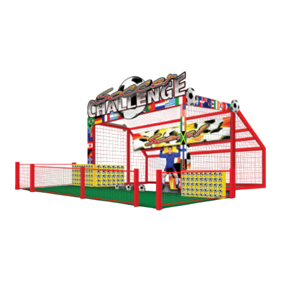
1. Introduction
BSR has simplified assembling the Football or Soccer Challenge™ by numbering the posts and sticking with only four types of
1.1
hardware. On the pages below is a section breakdown. The Goalie and Goal Cage must be assembled first. Next, assembling the
playfield. Lastly, put on the nets.
Bob's Space Racers® Inc. ©2018
Football/Soccer
Challenge™
Assembly Guide
Playfield
2
4
Playfield
3
Playfield
Figure 1.1
Bob's Space Racers® Inc. © 2018
427 Whac-A-Mole Way,
Holly Hill, Florida 32117
Phone - (386) 677-0761
Fax - (386) 677-0794
E-mail: tech@bobsspaceracers.com
Goal Cage
&
1
Goalie
P a g e
| 1
Advertisement

Subscribe to Our Youtube Channel
Related Manuals for Bob's Space Racers Football or Soccer Challenge


Summary of Contents for Bob's Space Racers Football or Soccer Challenge
- Page 1 1. Introduction BSR has simplified assembling the Football or Soccer Challenge™ by numbering the posts and sticking with only four types of hardware. On the pages below is a section breakdown. The Goalie and Goal Cage must be assembled first. Next, assembling the playfield.
- Page 2 2. Assemble First 2.1 Goalie Cage Back View LEFT SIDE RIGHT SIDE Figure 2.1 Bob’s Space Racers® Inc. ©2018 P a g e...
- Page 3 2.2 Goalie Secure to Bar 27 in Figure 2.1 above. Three ¼-20 x 1-inch bolts are used here Goalie Track Figure 2.2 Bob’s Space Racers® Inc. ©2018 P a g e...
- Page 4 3. Playfield 3.1 Right Side Figure 3.1 Bob’s Space Racers® Inc. ©2018 P a g e...
- Page 5 3.2 Left Side Figure 3.2 Bob’s Space Racers® Inc. ©2018 P a g e...
- Page 6 3.3 Front Goal Posts Come Pre-Assembled Note: These nets are pre-installed Figure 3.3 Bob’s Space Racers® Inc. ©2018 P a g e...
- Page 7 4. Net Installation Location Chart. Goalie Cage NET #4 NET #3 NET #6 Figure 4.1 Right Left Playfield Playfield NET #5 NET #6 NET #2 NET #1 NET #7 Figure 4.2 Figure 4.3 Bob’s Space Racers® Inc. ©2018 P a g e...
-
Page 8: Control Box Installation
5. Control Box Installation. Figure 5.1 Bob’s Space Racers® Inc. ©2018 P a g e... - Page 9 6. Each Number Corresponds to a Bolt Listed Below in the Chart Note: Each Bolt will have two washers and a nut when assembling. 3/8" X 3 1/2" 3/8" X 4 1/2" 3/8" X 5 1/2" 1/4-20 X 1" OLTS Table 6.1 Revision Date of Revision...
Need help?
Do you have a question about the Football or Soccer Challenge and is the answer not in the manual?
Questions and answers