Table of Contents
Advertisement
Quick Links
IP1851EN
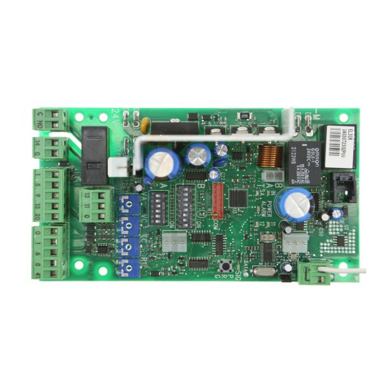
Ditec EL31R
Installation Manual for control panel for 24V automations with
built-in radio.
Motor
SBU
Safety switch
Transformer
F1
Power supply
www.ditecautomations.com
EL31R
-M
24V=
+M
B
A
IN
T
SA
B
ON
1
A
ON
1
24V~
SAFETY
C NO
14 0
www.ditecentrematic.com
ENC
JR1
11
12
POWER
COM
SIG
PRG
2 3 4 5 6 7 8
2 3 4 5 6
VA
VC
TC
R1
12
11
0
1 5 9 13 20
0 1 6 8 41
A
N
T
Limit switch
Limit switch
Advertisement
Table of Contents

Related Manuals for DITEC EL31R


Summary of Contents for DITEC EL31R
- Page 1 IP1851EN Ditec EL31R Installation Manual for control panel for 24V automations with built-in radio. EL31R Motor 24V= POWER 2 3 4 5 6 7 8 2 3 4 5 6 Safety switch 24V~ SAFETY Transformer Limit switch Limit switch C NO...
- Page 3 Index Subject Page General safety precautions EC declaration of conformity Technical specifications Applications Commands Self-controlled safety edge Sliding gates outputs and accessories Barriers outputs and accessories Settings Trimmers Sliding gates dip-switches Barriers dip-switches Jumper Signals Radio Working modes for sliding gates Start-up 10.1 Sliding gates start-up...
-
Page 4: General Safety Precautions
1. General safety precautions Failure to observe the information in this manual may result in minor personal injury or damage to equipment. Save these instructions for future reference. This installation manual is intended for qualified personnel only. Installation, electrical connections and adjustments must be performed in accordance with Good Working Methods and in compliance with the present standards. -
Page 5: Ec Declaration Of Conformity
2. EC Declaration of Conformity The manufacturer ASSA ABLOY ES AB, with headquarters in Lodjursgatan 10, SE-261 44 Land- skrona, Sweden, declares that the EL31R type control panel complies with the conditions of the following EC directives: EMC Directive 2004/108/EC Low Voltage Directive 2006/95/EC R&TTE Directive 1999/5/EC... - Page 6 4. Commands Command Function Description N.O. STEP-BY-STEP With DIP1A=OFF and TC<MAX, closing of the contact WITH AUTOMATIC activates an opening or closing operation in the following CLOSING sequence: opening-stop-closing-opening. NOTE: the stop is not permanent, but has the duration set with the TC trimmer. STEP-BY-STEP With DIP1A=OFF and TC=MAX, closing of the contact WITHOUT AUTOMATIC...
- Page 7 Command Function Description N.C. SAFETY SWITCH The SAFETY SWITCH contact is connected to the release system of the automation. Opening the release contact stops the operation. N.O. TRANSMITTER WARNING: the storage module must STORAGE AND CANCELLATION be inserted. Transmitter storage: - press the PRG key (the SIG LED turns on), - proceed with transmission from the transmitter to be stored (the SIG LED flashes),...
-
Page 8: Sliding Gates Outputs And Accessories
5. Sliding gates outputs and accessories Output Value - Accessories Description Accessories power supply. Power supply output for external accessories, including automa- 24 V 0.3 A tion status lamps. The control panel is fitted with a housing for a plug-in card, such as radio receivers, magnetic loops, etc. - Page 9 6. Barrier outputs and accessories Output Value - Accessories Description Accessories power supply. Power supply output for external accessories, including automa- 24 V 0,3 A tion status lamps. The control panel is fitted with a housing for a plug-in card, such as radio receivers, magnetic loops, etc.
- Page 10 Output Value - Accessories Description Lighting kit. 14 0 With DIP5A=ON, on with barrier closed, flashing with barrier operat- ing and off with barrier open. QIKLUX 24 V 300 mA max Electric block. 14 0 With DIP5A=ON it is activated with the barrier closed. QIKAFE 24 V 300 mA max Settings...
- Page 11 Sliding gates dip-switches DIP A Description DIP1A Command functions 1-5. Step-by-step Opening. NOTE: it also sets operating on the AUX plug-in card. DIP2A Selecting opening direction. Opening to the right. Opening to the left. The opening direction is intend- ed by viewing the automation from the side being examined.
- Page 12 Barrier dip-switches DIP A Description DIP1A Command functions 1-5. Step-by-step Opening. NOTE: it also sets operating on the AUX plug-in card. DIP2A Selecting opening direction. Opening to the right. Opening to the left. The opening direction is intend- ed by viewing the automation from the side being examined.
- Page 13 Jumper Jumper Description Built-in radio receiver Disabled Enabled Signals Flashing POWER Power supply on. Encoder not working or DIP5B se- ALARM lection is not consistent with the encoder actu- ally being or not being there. Current overload on flashing light output. Shortcircuiting of flashing light driver.
- Page 14 8. Radio The control panel is equipped with a radio receiver with a frequency of 433.92 MHz. The antenna consists of a rigid wire, 173 mm long, connected to the ANT clamp. It is possible to increase the range of the radio by connecting the antenna of the flashing lights, or by installing the tuned BIXAL antenna.
-
Page 15: Working Modes For Sliding Gates
Working modes for sliding gates The control panel can work in the following 3 modes: • automations with encoder (DIP5B=ON) and without stop limit switches, the automation stops on the mechanical stops; • automations with encoder (DIP5B=ON) and with stop limit switches, the automation stops after the stop limit switches have tripped;... - Page 16 10. Start-up 10.1 Starting the sliding gates WARNING The operations related to point 6 are performed without safeties. The trimmer can only be adjusted with the automation idle. The automation automatically slows when approaching the end stops or stop limit switches. After start-up the control panel receives a RESET and the first operation is performed at reduced speed (automation position acquisition).
- Page 17 10.2 Starting the barriers WARNING The operations related to point 6 are performed without safeties. The trimmer can only be adjusted with the automation idle. The automation automatically slows when approaching the end stops or stop limit switches. After start-up the control panel receives a RESET and the first operation is performed at reduced speed (automation position acquisition).
-
Page 18: Troubleshooting
11. Troubleshooting Problem Possible causes Operation The automation does not open or No power. Check that the control panel is close. (POWER ALARM LED off). powered correctly. Short circuited accessories. Disconnect all accessories from (POWER ALARM LED off). terminals 0-1 (a voltage of 24V= must be present) and reconnect them one at a time. - Page 19 The remote control has lim- The radio transmission is impeded Install the antenna outside. ited range and does not work by metal structures and reinforced with automation moving. concrete walls. Substitute the transmitter batter- ies.
-
Page 20: Application Example For Sliding Gates
12. Application example for sliding gates When using the control panel for sliding automation applica- tions: - Select the correct opening direction with DIP2A (Example 1). When using the <MAX 2 3 4 5 6 7 control panel for sliding gate ap- DIP2B=ON DIP1A=ON plications:... -
Page 21: Application Example For Barriers
13. Application example for barriers When using the control panel for <MAX DIP2B=ON 2 3 4 5 6 7 barrier applications: DIP5B=ON DIP1A=ON 2 3 4 5 6 - Select the correct opening direc- tion with DIP2A. Closing limit switch Opening limit switch C NO 14 0... - Page 22 15. Example of parallel automations JR1=NO JR2=CH1 2 3 4 5 6 7 2 3 4 5 6 7 DIP1A=ON DIP1A=ON DIP2A=ON 2 3 4 5 6 2 3 4 5 6 1 5 9 13 20 0 1 6 8 41 1 5 9 13 20 0 1 6 8 41 It is possible to command two automations [A] and [B] in parallel with the connections and settings...
- Page 24 ASSA ABLOY Entrance Systems AB Lodjursgatan 10 SE-261 44, Landskrona Sweden © ASSA ABLOY...
Need help?
Do you have a question about the EL31R and is the answer not in the manual?
Questions and answers