
Related Manuals for SystemAir CE 140 S-125


Summary of Contents for SystemAir CE 140 S-125
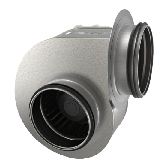
- Page 1 Installation, Operation and Maintenance instruction CE Centrifugal fan CT Centrifugal fan...
-
Page 2: Table Of Contents
Table of content 1 Introduction ............1 12.3 Wiring diagrams ........15 12.3.1 Wiring diagrams for AC fans .... 15 Product description ........1 12.3.2 Wiring diagrams for speed Intended use ..........1 controller for AC motors ....16 Document description........1 Product overview CE........ -
Page 3: Introduction
The procedures must be available and recommended as accessories. done by approved personnel only. Speak to Systemair for more information on how to install the product in different installation locations. Intended use The product is intended for transportation of clean air with a maximum temperature of 40–70 °C. -
Page 4: Product Overview
Note: The data on the name plate applies to “standard air” that is specified in the standard ISO5801. Use a mobile device to scan the scannable code and go to the Systemair documentation portal for more documentation and document translations. -
Page 5: Type Designation
230 V, 3–phase 400 V, 3–phase Product liability Safety Systemair is not liable for damages that the product causes Safety definitions in these conditions: • The product is incorrectly installed, operated or Warnings, cautions and notes are used to point out specially maintained. -
Page 6: Personal Protective Equipment
–10 and +30 °C. A stable ambient • Sound levels exceeding 70 dB(A) may occur depending temperature prevents damage from condensation. on model and size. Visit www.systemair.com for more de- tailed information about your product. • Keep the product in storage for maximum 1 year. -
Page 7: Installation
Use the fast clamps to attach the duct to the product. Systemair recommends to use FK fast clamps to attach – If you install the product outdoors, it is necessary to in- the duct to the product. The FK fast clamps are available stall a weather protection roof. - Page 8 If you install the product near a duct bend, do these guide rails to attach the flexible connections to the duct. steps to prevent vibrations, unwanted noise and de- Guide rails are not supplied by Systemair. creased air pressure: Measure the distance (A) between the product and Flexible connection USE is available as an accessory.
-
Page 9: Electrical Connection
The commissioning report is found at www.systemair.com. To connect the product to the power supply To do before the •... -
Page 10: Operation
Operation To start a product with an AC motor Set the installed safety switch in the ON position. Install the external speed controller. Refer to the instruc- tion manual for the installed speed controller. To stop the product Set the installed speed controller in the OFF position. Refer to the instruction manual for the installed speed controller. -
Page 11: To Clean The Product
• When you send an order for spare parts, include the serial number of the product. The serial number is found on the name plate. Troubleshooting Note: If you cannot find a solution to your problem in this section, speak to Systemair technical support. - Page 12 Problem Cause Solution The fan impeller is not correctly Speak to Systemair technical support. balanced. There is dirt on the fan impeller. Clean the fan impeller carefully. Refer 8.2 To clean the product page The fan impeller has damages or Speak to Systemair technical support.
- Page 13 This is not applicable for EC motors or 3–phase AC motors. There is blockage in the motor. Speak to Systemair technical support. Defective motor winding. If it is possible, measure the resistance to do a check of the motor winding.
-
Page 14: Disposal
Disposal 10.1 To disassemble and discard the parts of the product The product follows the WEEE directive. This symbol on the product or the packaging of the product shows that this Disconnect and disassemble the product in the opposite product is not domestic waste. The product must be recycled sequence of electrical connection and installation. -
Page 15: Warranty
12.1 Technical data overview Max. temperature of transported air, °C Max. ambient temperature, °C Refer to the data sheet in the online catalogue at www.systemair.com. Sound pressure, dB IP class Voltage, current, frequency, enclosure Refer to the name plate. Refer to 1.6 Name plate page 2... -
Page 16: Product Dimensions Ct Fans
ØA ØI CE 140 S-125, 140 L-125 CE 140 L-160, M-160 12.2.2 Product dimensions CT fans Note: If the unit of measure is not specified, the dimensions are given in millimetres. ØF CE 225–4 CE 250–4 CT 280–4 CT 315–4... -
Page 17: Wiring Diagrams
Green Brown Black Grey Green/Yellow 12.3.1 Wiring diagrams for AC fans CE fans 1–phase 230 V CE 140 S-125 CE 140 L-125 CE 140 L-160 CE 140 M-160 CT fans CT 200–4 CT 225–4 TK TK CT 250–4 CT 280–4 TK TK W2 U1 U2 V1 V2 W1 CT 315–4... -
Page 18: Controller For Ac Motors
12.3.2 Wiring diagrams for speed controller for AC motors Note: The selection of electrical accessories must be done in line with the technical parameters of the product. Manual 5-step transformer. RE 1,5 RE 3 RE 5 RE 7 Relay connection. There is always 230 V between ~ and N when the transformer knob is in one of the positions 1–5. Mains supply C. - Page 19 RTRE Manual 5-step transformer with motor protection. RTRE 1,5 RTRE 3 RTRE 5 RTRE 7 RTRE 12 Relay connection. There is always 230 V between ~ and N when the transformer knob is in one of the positions 1–5. Mains supply C.
- Page 20 Contact rating, maximum AC 250 V/2 A Mains supply, 1–phase 208...277 V, 50/60 Hz C. Motor with internal thermal contacts D. OFF/ON RTRD A 3-phase transformer that controls the fan speed by altering the supply voltage in five fixed steps. The steps are adjusted by using the control knob on the front of the unit.
- Page 21 RTRDU Manual 5–step transformer with motor protection — a 3–phase transformer that controls the fan speed by altering the supply voltage in five fixed steps. The steps are adjusted by using the control knob on the front of the unit. RTRDU FS FS TB TB...
-
Page 22: Accessory Overview
RSK: Back draft damper VBC: Water heating battery FK: Fast clamp CB and CBM: Electrical duct heaters SPI: Iris damper LDC: Silencer 10. Balance S supply air diffuser Note: For more information about accessories, refer to www.systemair.com or speak to Systemair technical support. -
Page 23: Accessory Overview
FGR/FFR: Filter cassette VBR: Water heating battery ISE: Flexible connection RB: Electrical duct heaters SRK: Volume control damper USE: Flexible connection 10. Balance S supply air diffuser Note: For more information about accessories, refer to www.systemair.com or speak to Systemair technical support. -
Page 24: Eu Declaration Of Conformity
EU Declaration of Conformity We, the manufacturer Manufacturer Systemair Sverige AB Address Industrivägen 3 739 30 Skinnskatteberg Sweden declare under our sole responsibility that the products Type/Model CE, CT Identification Serial numbers dating from 2022 and onwards fulfils the relevant provisions of following directives and... -
Page 25: Declaration Of Conformity
UK Declaration of Conformity We, the manufacturer Manufacturer Systemair Sverige AB Address Industrivägen 3 SE-73930 Skinskatteberg Sweden declare under our sole responsibility that the products Type/Model CE, CT Identification Serial numbers dating from 2022 and onwards fulfils the relevant provisions of following directives and... - Page 26 © Copyright Systemair AB All rights reserved Systemair AB reserves the rights to alter their products without notice. This also applies to products already ordered, as long as it does not affect the previously agreed specifications. Original instructions 2022-05-20...
Need help?
Do you have a question about the CE 140 S-125 and is the answer not in the manual?
Questions and answers