Table of Contents
Advertisement
Quick Links
Advertisement
Table of Contents

Related Manuals for Nuvico Easy View 2 CD Series


Summary of Contents for Nuvico Easy View 2 CD Series
- Page 1 All manuals and user guides at all-guides.com...
-
Page 2: Disclaimer
NUVICO. • NUVICO makes no warranties for damages resulting from corrupted or lost data due to a mistaken operation or malfunction of the cameras, peripheral devices, or unapproved/... -
Page 3: Warning And Caution
All manuals and user guides at all-guides.com Warning and Caution WARNING! TO REDUCE THE RISK OF FIRE OR ELECTRIC SHOCK, DO NOT EXPOSE THIS PRODUCT TO RAIN OR MOISTURE. DO NOT INSERT ANY METALLIC OBJECTS THROUGH THE VENTILATION GRILLS OR OPENINGS ON THE EQUIPMENT. CAUTION! The lightning flash with arrowhead symbol, within an equilateral triangle, is intended to alert the user to the presence of uninsulated “dangerous voltage”... -
Page 4: Fcc Compliance Statement
All manuals and user guides at all-guides.com FCC Compliance Statement FCC INFORMATION : THIS EQUIPMENT HAS BEEN TESTED AND FOUND TO COMPLY WITH THE LIMITS FOR A CLASS A DIGITAL DEVICE, PURSUANT TO PART 15 OF THE FCC RULES. THESE LIMITS ARE DESIGNED TO PROVIDE REASONABLE PROTECTION AGAINST HARMFUL INTERFERENCE WHEN THE EQUIPMENT IS OPERATED IN A COMMERCIAL ENVIRONMENT. -
Page 5: Important Safeguards
All manuals and user guides at all-guides.com Important Safeguards • Read these instructions. • Heed all warnings. • Follow all instructions. • Do not use this equipment near water. • Clean only with dry cloth. • Do not block any ventilation openings. Install in accordance with the manufacturer’s instructions. -
Page 6: Table Of Contents
All manuals and user guides at all-guides.com Table of Contents ..................... Disclaimer ..................Warning and Caution ................FCC Compliance Statement ................CE Compliance Statement .................. Important Safeguards ..................Table of Contents ..............Introduction / Available Models ..................Content Verification ..................Parts &... - Page 7 ..................5.4 SHARPNESS ..................5.5 LANGUAGE ..................5.6 EDIT TITLE ................5.7 FACTORY DEFAULT ............EZ-Coax™ (NUVICO Telemetry Control) ..............Technical Specifications | NTSC ..............Technical Specifications | NTSC ..............Technical Specifications | PAL ..............Technical Specifications | PAL ............
-
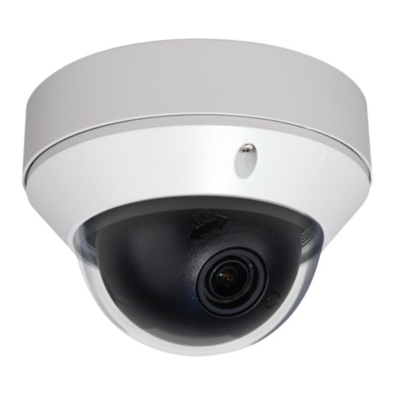
Page 8: Introduction / Available Models
All manuals and user guides at all-guides.com Introduction ABOUT THIS MANUAL Thank you for purchasing our EasyView™2 dome camera. Our EasyView™2 Dome Cameras are all equipped with high resolution 1/3” Interline transfer CCD Imager for enhanced low light sensitivity. Combined with our 2nd generation ‘Super Image Enhancer II’... -
Page 9: Content Verification
All manuals and user guides at all-guides.com Content Verification Before installing the camera, please make sure that all of the following items are included in the box. INDOOR ST Series & STD Series 1. EasyView™2 Dome Camera 2. Installation Manual 3. -
Page 10: Parts & Descriptions
All manuals and user guides at all-guides.com Parts & Descriptions Lens Power input Connctor 12VDC/24VAC Dual Voltage Video Output Connector - BNC Service Monitor Output Connector Model #: CA-SMC30 Camera Control Board Safety Wire Bubble Dome Cover Flush Mount Base Surface Mount Plate Assembly Screws Philips M4x9 (Indoor) -
Page 11: Camera Dimensions
All manuals and user guides at all-guides.com Camera Dimensions See the diagrams below for the exact dimensions for both the Flush Housing and the Surface Mount Housing. Dimensions Unit: mm Flush Mount Surface Mount (I) Indoor, (V) Vandalproof NOTE: The Surface Mount Base for all outdoor vandalproof EasyView™... -
Page 12: Base Installations
All manuals and user guides at all-guides.com Base Installations Remove the dome cover by loosening the 3 screws located at the Dome Cover Ring. EasyView™2 indoor domes use the standard philips screws, while vandal domes uses the torx screws. Use the Torx Wrench supplied. Surface Mount Using four ST4x30 screws provided, mount the surface mount plate to a strudy sur- face. -
Page 13: Mounting On Electrical Junction Box
All manuals and user guides at all-guides.com Mounting on Electrical Junction Box Designed for both flush mount or surface mount applications, pre-drilled mounting holes on EasyView™ dome accommodate various electrical junction boxes, making installation easy and less time consuming. When mounting the flush mount base, surface mount plate, or both together, use the pre-drilled holes marked with the symbol for proper installation. -
Page 14: Connecting To Monitors
All manuals and user guides at all-guides.com Connecting to Monitors Follow the diagram below to make proper connections to the CRT Monitor or the Service Monitor. • Power connection -12VDC/24VAC Dual Voltage(Auto polarity detection and protection) • All cameras are equipped with a service monitor output on the camera module. -
Page 15: Adjusting The Vari-Focal Dc Auto Iris Lens
All manuals and user guides at all-guides.com Adjusting the Vari-focal DC Auto Iris Lens Follow the instruction provided below to make any lens adjustments. Adjust Focus Adjust Angle for Field of View Zoom: Wide ^ - a Tele Focus: Far ^ - a Near Loosen the Zoom &... -
Page 16: Adjusting The 3-Axis Gimbal
All manuals and user guides at all-guides.com Adjusting the 3-Axis Gimbal The Gimbal mechanism yields maximum rotation and placement as shown below. Z-Axis: Rotation 355° Y-Axis: Tilting 85°/ 75° IR LED X-Axis: Panning 240° Rotation 355° Panning 240° Tilting 85° Tilting 75°... -
Page 17: Camera Osd Setup Controls
All manuals and user guides at all-guides.com Camera OSD Setup Controls Please use the directional keys located at the bottom of the Gimbal base to make the desired changes in the OSD menu. Directional Navigation Keys Down Key Right Key Enter Key Left Key Up Key... -
Page 18: Osd Menu Control & Navigation
All manuals and user guides at all-guides.com OSD Menu Controls & Navigation OSD MENU CONTROLS (On-Screen-Display) Enter Key - Used to access MAIN SETUP menu mode. Up / Down Key - Used to scroll through the desired sub-menu selection and to move the cursor up or down during the OSD menu. -
Page 19: Osd Menu Terms & Settings
All manuals and user guides at all-guides.com OSD Menu Terms & Settings 1. AE SETUP (Automatic Exposure) The AE SETUP is used to control the video output levels under different intensities in the lighting. 1.1 MODE: ALC (Automatic Level Control) The ALC mode and the camera will continuously monitor changes in the lighting intensity and automatically adjust the Iris to the most optimal level. -
Page 20: Max Agc
All manuals and user guides at all-guides.com OSD Menu Terms & Settings 1.5 MAX AGC (OFF, 8dB a ... a36dB) The AGC will compensate the gain levels automatically up to the pre-determined maximum. The MAX AGC limit can be set as low as 8dB, or as high as 36dB(MAX). The factory default limit is 22dB. -
Page 21: Wb Setup (White Balance)
All manuals and user guides at all-guides.com OSD Menu Terms & Settings 2. WB SETUP (White Balance) The WB SETUP is used to control the white balance under different illumination sources. Adjust this setting to calibrate the camera for correct color rendering. The factory default of ‘AWC AUTO’... -
Page 22: Control
All manuals and user guides at all-guides.com OSD Menu Terms & Settings 2.2 CONTROL - WB Mode Control (LOCK, AUTO, CRLS, 3200°K, 5400°K, R/B CTRL) • This field displays the current CONTROL status of the WB mode. In the AWC LOCK mode, the user may control the white balance after pointing the camera to the desired location. -
Page 23: Blc Setup (Back Light Compensation)
All manuals and user guides at all-guides.com OSD Menu Terms & Settings 3. BLC SETUP (Back Light Compensation) The BLC SETUP is used to control the various Back Light Compensation modes available in the EasyView™ 2 dome camera. BLC can assist in compensating for exposure problem associated with very bright backgrounds causing subjects to bloom or silhouette. -
Page 24: Bmb Mode Menu (Brightlight Masking Block)
All manuals and user guides at all-guides.com OSD Menu Terms & Settings 3.3 BMB Mode Menu (Brightlight Masking Block) To activate or deactivate specific areas to be masked by BMB, follow the simple instructions below 1. Select the BMB mode, then scroll down to AREA SEL and press the LEFT/RIGHTKey. 2. -
Page 25: Ir Adj
All manuals and user guides at all-guides.com OSD Menu Terms & Settings 4. IR ADJ Note: IR ADJ option is only available with the STD Series Day/Night IR LED model. IR LED Intensity This function is used to adjust the intensity of the IR LED. Too much IR reflection from a subject causes over-exposure on the most focused area causing ‘Hot Spots’... -
Page 26: Special
All manuals and user guides at all-guides.com OSD Menu Terms & Settings 5. SPECIAL The Special Setup is used to control the MOTION, PRIVACY MASK, DNR, SHARPNESS, LANGUAGE, EDIT TITLE, and FACTORY DEFAULT of the dome camera. 5.1 MD SETUP - Motion Detection •OPERATION: Select this function ON or OFF. -
Page 27: Pzm Set (Private Zone Masking)
All manuals and user guides at all-guides.com OSD Menu Terms & Settings 5.2 PZM SET (Private Zone Masking) The PZM is used to mask specific areas within the frame of the camera to be concealed. A total of 8 areas can be masked. To setup the Privacy Zone masks, follow the simple instructions below. -
Page 28: Dnr (Digital Noise Reduction)
All manuals and user guides at all-guides.com OSD Menu Terms & Settings 5.3 DNR - Digital Noise Reduction (OFF, LOW, HIGH) The DNR improves picture quality by filtering out signal noise associated with night-time recording. It compares pictures from a frame with the one previous and removes noise grains not present before. -
Page 29: Factory Default
All manuals and user guides at all-guides.com OSD Menu Terms & Settings 1. Select the DISPLAY, then change the setting to “ON” using the LEFT/RIGHT keys. 2. Scroll down to the bottom and input the desired custom title (10-digits MAX). A custom title may be entered by pressing the ENTER key while highlighting the desired letter, number, or symbol shown above. -
Page 30: Ez-Coax™ (Nuvico Telemetry Control)
EZ-Coax™ (NUVICO Telemetry Control) Model numbers with “-CX” attachment indicates cameras equipped with EZ-Coax™. EZ-Coax™ is the NUVICO up-the-coax telemetry control that grants access to the EasyView2 OSD menu using only the coax cable already running from the camera. Refer to the diagram below for a typical EZ-Coax™ transceiver connection configuration,... -
Page 31: Technical Specifications | Ntsc
All manuals and user guides at all-guides.com Technical Specifications | NTSC Technical Specifications CD-ST21N CD-STD21N Video Format NTSC NTSC Image Sensor 1/3” CCD 1/3” CCD Horizontal Resolution 580 TV Lines 580 TV Lines Day / Night Functionality Yes w/ ICR Lens Type (DC Auto Iris) Vari-focal 2.8mm-10mm Vari-focal 2.8mm-10mm... -
Page 32: Technical Specifications | Ntsc
All manuals and user guides at all-guides.com Technical Specifications | NTSC Technical Specifications CD-STD21N-L Video Format NTSC Image Sensor 1/3” CCD Horizontal Resolution 580 TV Lines Day / Night Functionality Yes w/ ICR Lens Type (DC Auto Iris) Vari-focal 2.8mm-10mm Angle of View 131.6°(W) ~ 35.6°(T) IR LED... -
Page 33: Technical Specifications | Pal
All manuals and user guides at all-guides.com Technical Specifications | PAL Technical Specifications CD-ST21PA CD-STD21PA Video Format APAL Image Sensor 1/3” CCD 1/3” CCD Horizontal Resolution 580 TV Lines 580 TV Lines Day / Night Functionality Yes w/ ICR Lens Type (DC Auto Iris) Vari-focal 2.8mm-10mm Vari-focal 2.8mm-10mm Angle of View... -
Page 34: Technical Specifications | Pal
All manuals and user guides at all-guides.com Technical Specifications | PAL Technical Specifications CD-STD21P-LA Video Format Image Sensor 1/3” CCD Horizontal Resolution 580 TV Lines Day / Night Functionality Yes w/ ICR Lens Type (DC Auto Iris) Vari-focal 2.8mm-10mm Angle of View 131.6°(W) ~ 35.6°(T) IR LED IR LED Distance... -
Page 35: Easyview™ Dome Camera Accessories
All manuals and user guides at all-guides.com EasyView™ Dome Camera Accessories The following are various mounting accesssories available for the EasyView series dome cameras. Indoor Wall Mount Universal Corner Mount Bracket | CV-WM | CA-CMB Ideal for indoor applications. Ideal for mounting camera on corners of a structure. -
Page 36: Fan & Heater Installation Instructions | Cv-Fh
All manuals and user guides at all-guides.com Fan & Heater Installation Instructions | CV-FH FEATURES This Fan and Heater assembly is designed for EasyView™ vandalproof dome camera. Assembly Accessories Assembly Screw Assembly Screw Philips M2.6x14 Philips M3x6 Q’ty: 1 Q’ty: 1 Length: 14 mm Length: 6 mm Thickness: 2.6 mm... -
Page 37: Indoor Wall Mount Installation Instructions | Cv-Wm
All manuals and user guides at all-guides.com Indoor Wall Mount Installation Instructions | CV-WM FEATURES This indoor wall mount is designed for EasyView™ dome camera . This mount can be directly to a wall or attached to a junction box (CA-JB). Assembly Accessories Assembly Screws Note: Mounting... -
Page 38: Outdoor Wall Mount Installation Instructions | Ca-Om
All manuals and user guides at all-guides.com Outdoor Wall Mount Installation Instructions | CA-OM FEATURES This outdoor wall mount is designed for EasyView™ dome camera and the EasyTrak™ MIni PTZ camera. This mount can be directly to a wall or attached to a junction box (CA-JB). Assembly Accessories Mounting Screw Anchors... - Page 39 All manuals and user guides at all-guides.com...
- Page 40 All manuals and user guides at all-guides.com 050600003600...
Need help?
Do you have a question about the Easy View 2 CD Series and is the answer not in the manual?
Questions and answers