Table of Contents

Related Manuals for StarTech.com VS321HDBTK


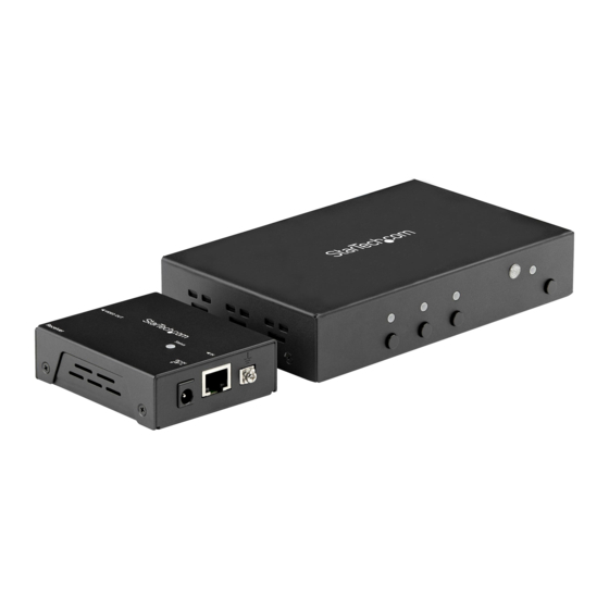
Summary of Contents for StarTech.com VS321HDBTK
- Page 1 Multi-Input HDMI® over HDBaseT Extender with Built-In Switch Actual product may vary from photos User Manual SKU#: VS321HDBTK For the latest information and specifications visit www.startech.com/VS321HDBTK Manual Revision: 09/12/2019...
-
Page 2: Compliance Statements
Industry Canada Statement This Class B digital apparatus complies with Canadian ICES-003. Cet appareil numérique de la classe [B] est conforme à la norme NMB-003 du Canada. CAN ICES-3 (B)/NMB-3(B) To view manuals, videos, drivers, downloads, technical drawings, and more visit www.startech.com/support... - Page 3 This manual may make reference to trademarks, registered trademarks, and other protected names and/or symbols of third-party companies not related in any way to StarTech.com. Where they occur these references are for illustrative purposes only and do not represent an endorsement of a product or service by StarTech.com, or an endorsement of the product(s) to which this manual...
-
Page 4: Safety Statements
• Montering av kabelavslutningar får inte göras när produkten och/eller elledningarna är strömförda. • Kablar (inklusive elkablar och laddningskablar) ska dras och placeras på så sätt att risk för snubblingsolyckor och andra olyckor kan undvikas. To view manuals, videos, drivers, downloads, technical drawings, and more visit www.startech.com/support... -
Page 5: Table Of Contents
Mode Switch ............................... 9 EDID Settings .............................. 9 Standby Mode ............................10 Remote Control ............................11 Input Selection Buttons .......................... 12 Manual Operation with Serial Control Port ..................12 To view manuals, videos, drivers, downloads, technical drawings, and more visit www.startech.com/support... -
Page 6: Product Diagram
• Indicates the status of the Transmitter Status LED Indicator • Select an active HDMI Input Port Input Selection Buttons • Enter or exit Standby Mode Standby Button To view manuals, videos, drivers, downloads, technical drawings, and more visit www.startech.com/support... -
Page 7: Transmitter Rear View
• Connect a Grounding Wire to prevent a System Ground ground loop. • Connect the Receiver via CAT5e/6 Cable Video Link Output Port • Indicates the EDID Copy status EDID LED Indicator To view manuals, videos, drivers, downloads, technical drawings, and more visit www.startech.com/support... -
Page 8: Receiver Front View
Receiver Front View Port Function • Connect an HDMI Display Device HDMI Output Source To view manuals, videos, drivers, downloads, technical drawings, and more visit www.startech.com/support... -
Page 9: Receiver Rear View
(located on the top of the Receiver) • Connect a Grounding Wire to prevent a System Ground ground loop. • Connect the Transmitter via CAT5e/6 Video Link Input Port Cable To view manuals, videos, drivers, downloads, technical drawings, and more visit www.startech.com/support... -
Page 10: Requirements
For applications using specialized Grounding Wires: • Loosen the Screw(s) all the way and insert the Screw(s) • through the Grounding Wire ends before retightening into the Transmitter and Receiver. To view manuals, videos, drivers, downloads, technical drawings, and more visit www.startech.com/support... - Page 11 HDMI Source Devices. Control) Connect the RJ11 to RS232 (Optional - for Serial Adapter to the Serial Control Port on the Transmitter and to a Serial Port on your Computer. To view manuals, videos, drivers, downloads, technical drawings, and more visit www.startech.com/support...
-
Page 12: (Optional) Mounting
Holes in the bottom of the Receiver. Insert two Screws through the Mounting Bracket and into the Receiver. Mount the Receiver to the desired Mounting Surface using the appropriate Mounting Hardware (ex. Wood Screws). To view manuals, videos, drivers, downloads, technical drawings, and more visit www.startech.com/support... -
Page 13: Operation
HDBaseT is linked Solid blue EDID LED Indicator LED Behavior Status Flashing two times EDID copy Flashing three times (long flash - Auto EDID short flash - short flash) To view manuals, videos, drivers, downloads, technical drawings, and more visit www.startech.com/support... -
Page 14: Mode Switch
Auto select a priority HDMI Source Priority (HDMI Input 1, 2, then 3) Auto select the last connected Auto HDMI Source Select the HDMI Source using the Switch Input Selection Buttons To view manuals, videos, drivers, downloads, technical drawings, and more visit www.startech.com/support... -
Page 15: Edid Settings
Transmitter and Receiver go into a low power mode. To enter Standby Mode: Press and Hold the Standby • Button for 3 seconds. To exit Standby Mode: Press and Release the Standby • Button. To view manuals, videos, drivers, downloads, technical drawings, and more visit www.startech.com/support... -
Page 16: Remote Control
Remote Control The Remote Control can be used to remotely select your HDMI Source Device and to change the Standby Mode settings. The Remote Control operates through line-of-sight. Always point the Remote Control directly at the infrared sensor on the Transmitter, with no objects obstructing the signal path. -
Page 17: Input Selection Buttons
Open a third-party Terminal Software to communicate through the Serial Control Port and use the on-screen commands, displayed on the next page, to operate and configure the Transmitter and Receiver. To view manuals, videos, drivers, downloads, technical drawings, and more visit www.startech.com/support... - Page 18 7. Dolby E-AC3 7.1 ch 8. DTS 5.1 ch 9. DTS HD 5.1 ch 10. DTS HD 7.1 ch 11. MPEG4 AAC 5.1 ch 12. 5.1 ch combination 13. 7.1 ch combination To view manuals, videos, drivers, downloads, technical drawings, and more visit www.startech.com/support...
- Page 19 0- Reset as null(Always on) 1~16 - Valid ID IT=n Set terminal interface n: 0 - Human 167 - Machine LCK=n Lock / Unlock device n: 0 - Unlock 167 - Lock To view manuals, videos, drivers, downloads, technical drawings, and more visit www.startech.com/support...
- Page 20 Limitation of Liability In no event shall the liability of StarTech.com Ltd. and StarTech.com USA LLP (or their officers, directors, employees or agents) for any damages (whether direct or indirect, special, punitive, incidental, consequential, or otherwise), loss of profits, loss of business, or any pecuniary loss, arising out of or related to the use of the product exceed the actual price paid for the product.
- Page 21 StarTech.com is an ISO 9001 Registered manufacturer of connectivity and technology parts. StarTech.com was founded in 1985 and has operations in the United States, Canada, the United Kingdom and Taiwan servicing a worldwide market.
Need help?
Do you have a question about the VS321HDBTK and is the answer not in the manual?
Questions and answers