
Subscribe to Our Youtube Channel
Related Manuals for LifeFitness G3


Summary of Contents for LifeFitness G3
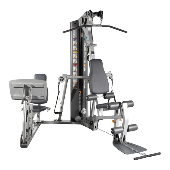
- Page 1 LEG PRESS ADAPTER KIT FOR G3 GYM SYSTEM WARNING: Read and follow all directions for each step to ensure proper assembly of this product. USER’S GUIDE G3-GLPA-101 Revision: 07/17/08...
- Page 2 9. Children must not be allowed near this machine. Supervise teenagers. Note: In our continuing effort to improve our products, specifications are subject to change. ©2006 Life Fitness, a division of Brunswick Corporation. All rights reserved. www.lifefitness.com...
- Page 3 MPORTANT OTES Thank you for purchasing the Life Fitness G3 Leg Press Adapter Kit. Please read these instruc- tions thoroughly and keep them for future reference. This product must be assembled on a flat, level surface to assure its proper function. DO NOT securely tighten any frame connections until the entire frame has been assembled, unless otherwise stated.
- Page 4 3/8” WASHER STEP SPACER 1-11/16’LG 3/8” LOCKNUT CABLE L CLIP Note: The LEG PRESS ATTACHMENT(GLP) must be assembled before connecting it to the Lift Fitness G3 GYM SYSTEMS DISCARD! WEIGHT STACK CABLE IGURE • Remove the WEIGHT STACK CABLE as shown in FIGURE 1. Discard the cable..
- Page 5 3/8 X 1-3/4” 9 IGURE • Screw the long threaded end of the new WEIGHT STACK CABLE (3) into the end of the WEIGHT PLATE SHAFT. See FIGURE 2. • Route the WEIGHT STACK CABLE (3) around the pulley in the BOOM PLATES as shown in FIG- URE 2.
- Page 6 IGURE • Screw the threaded end of LEG PRESS CABLE (4) to the PULLEY BRACKET (2) as shown in FIGURE 3.
- Page 7 IGURE • If not already installed, slide one 2” SQ. COVER CAP (6) over the FRONT LEG (1) as shown in FIGURE 4. 3/8” LOCKNUT 3/8 X 3-3/4” BOLT • Remove the 3/8 X 3-3/4” BOLT and 3/8” LOCK NUT from the BASE PLATE as shown in FIGURE 5.
- Page 8 11 3/8 X 4” IGURE • SECURELY assemble the LEG PRESS ADAPTOR (1) to the G3 Gym System using two 3/8 X 4” BOLTS (11), five 3/8” WASHERS (7), one previously removed 3/8” LOCK NUT and one 3/8” LOCK NUT (8) as shown in FIGURE 6.
- Page 9 10 3/8 X 2-3/4” IGURE • SECURELY attach the GLP LEG PRESS to the LEG PRESS ADAPTOR (1) using two 3/8” X 2- 3/4” BOLTS (10), two 3/8” WASHERS (7), and two 3/8” LOCK NUTS (8). See FIGURE 8. SEAT FRAME BRACKET IGURE 3/8 X 1-3/4”...
- Page 10 SEAT FRAME BRACKET 3/8” LOCK NUT IGURE 3/8 X 4-3/4” • SECURELY attach the BRACKET (from GLP LEG PRESS) to the SEAT FRAME using two 3/8” X 4-3/4” BOLTS (12), two 3/8” WASHERS (7), and two 3/8” LOCK NUTS (8). See FIGURE 10. 3/8 X 1-3/4”...
- Page 11 IGURE SEAT FRAME 3/8” LOCK NUT • Carefully route the LEG PRESS CABLE (4) around one 3-1/2” PULLEY (5) and SECURELY assemble the 3-1/2” PULLEY (5) to the SEAT FRAME using one 3/8 X 4-3/4” BOLT (12), two STEP SPACERS 1-19/32 (14), and one 3/8” LOCK NUT (8) as shown in FIGURE 12. Make sure the CABLE is in the grooves of all the pulleys.
- Page 12 SEAT FRAME 3/8” LOCK NUT 3/8 X 4-3/4” IGURE • SECURELY assemble the swivel end of the LEG PRESS CABLE (4) to the SEAT FRAME using one 3/8 X 4-3/4” BOLT (12), two STEP SPACERS 1-11/16”(15) and one 3/8”LOCK NUT (8). NOTE: SECURELY tighten, then back nut off 1/4 turn ABLE OUTING...
- Page 13 WEIGHT SELECTOR PIN and perform several repititions at the leg press station.This will relax the cable system and prevent the HEAD PLATE from lifting up. • If further CABLE ADJUSTMENT is needed, reference the G3 GYM SYSTEM assembly instruc- tions.
Need help?
Do you have a question about the G3 and is the answer not in the manual?
Questions and answers