
Related Manuals for Eaton Crouse-Hinds MTL F890


Summary of Contents for Eaton Crouse-Hinds MTL F890
- Page 1 Instruction manual March 2022 MTL fieldbus networks INM F890 Rev 1 MTL F890 8 Segment Redundant Fieldbus Power Supply for use with non-proprietary cabled systems...
- Page 2 THIS PAGE IS LEFT INTENTIONALLY BLANK INM F890 Rev 1...
-
Page 3: Table Of Contents
CONTENTS OVERVIEW . . . . . . . . . . . . . . . . . . . . . . . . . . . . . . . . . . . . . . . . . . . . . . . . . . . . . . . . . . . . . . . . . . . . . . . . 1 DESCRIPTION . -
Page 4: Overview
MTL F890 - 8 Segment Redundant Fieldbus Power Supply for use with the non-proprietary cabled systems Figure 1 - F890-PS OVERVIEW The F890 redundant fieldbus power supply is designed to provide redundant power for eight (8) Foundation fieldbus H1 segments. Pluggable connectors are provided on the F890-CA module carrier for connection to the eight segments as well as the eight Host H1 ports. -
Page 5: Components And Accessories
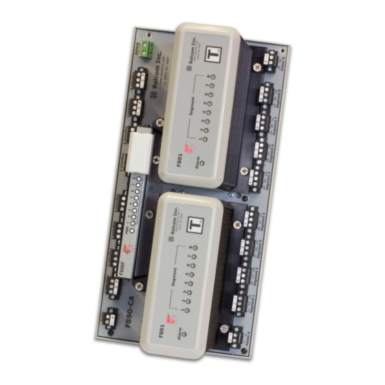
segment is automatically maintained when single or redundant Power Modules are fitted. The F890-CA carrier is equipped with connectors that will accept an F809F diagnostic module. The module continuously monitors the performance of each of the eight fieldbus segments, providing information on the network health. Each Power Module has indicator LEDs to show both its status and that of the eight segments under power. - Page 6 Figure 2 - F890-CA Carrier Only units produced after date code 0726 include the Diagnostic Segment connectors. The Shield Ground Option is available on revision E.0 and later units. INM F890 Rev 1...
-
Page 7: Mechanical
MECHANICAL 4 .1 Mounting Orientation The F890-CA carriers are designed for mounting on a vertically aligned DIN-rail on a vertical surface. This method of mounting ensures optimum heat dissipation from the Power Modules. 4 .2 Enclosure Requirements 4 .2 .1 General Requirements The assembly may be mounted in hazardous (classified) areas –... -
Page 8: Removal From Din-Rail
Press the carrier onto the DIN-rail and rotate each of the DIN clamp screws clockwise until the tab tightens against the DIN-rail. The clamping tabs can be seen through the Inspect clamps holes when they are in the correct position. 4 .4 Removal from DIN-rail The Power Modules must be removed from the carrier to obtain access to the DIN-... -
Page 9: Dc Power Requirements
The DC power, Alarm and Field Segment connectors are pluggable and available in a screw terminal version (-xS) or a spring clamp version (-xC). See Figures 5a & 5b. The terminals can accept the following conductor sizes: Type Conductor size Screw terminals (-PS) 0.14 to 2.5mm Spring clamp terminals (-PC) -
Page 10: Power A And Power B
5 .2 Power A and Power B Power A supplies Power Module A and Power B supplies Power Module B. Each module provides DC power to all eight segments - see Figure 4. DC supply connections are as follows: Power A Power B Pin No. -
Page 11: Final Segment Connections
ALARM F8xx-Cx ALARM F8xx-Cx Figure 6 - “Daisy chaining” alarm contacts 5 .4 Host Connections Connectors are provided to permit direct connection via AKB336 cables to Yokogawa ALF111 cards. Four connectors are fitted to provide the following connections. Pin No . Connection Pin No . -
Page 12: Cable Screen / Ground Connections
Segment 3 - Segment 7 - Segment 4 + Segment 8 + Segment 4 S Segment 8 S Segment 4 - Segment 8 - 5 .6 Cable Screen / Ground Connections For revision E .0 or higher units – Provisions have been made to facilitate tying the 8 screens together and bringing them to the common Screen Ground terminal 53. -
Page 13: Diagnostic Segment Connectors
5 .8 Diagnostic Segment Connectors Two Diagnostic Segment connectors are available for use in conjunction with the optional F809F Diagnostic Module. These connectors are only available on units with date codes after 0726. Please see the Installation Manual for the F809F for further information. -
Page 14: Fm Control Drawings
FM CONTROL DRAWINGS INM F890 Rev 1... - Page 15 HAZARDOUS (CLASSIFIED) LOCATION WARNING: Class I, Division 2, Groups A, B, C, D, T4 EXPLOSION HAZARD - DO NOT DISCONNECT Class I, Zone 2, IIC T4 EQUIPMENT UNLESS POWER HAS BEEN SWITCHED -40C <= Tamb <= 65C OFF OR THE AREA IS KNOWN TO BE NON-HAZARDOUS. -40C <= Tamb <= 50C (F802 total load >...
-
Page 16: Atex & Ukca Safety Information
FM Special Conditions of Use 1. The F801/F802 Fieldbus Supply Modules and Carriers shall be installed in compliance with the enclosure, mounting, spacing and segregation requirements of the ultimate application, including a tool removable cover. 2. When installed in hazardous (classified) locations, a warning label must be prominently affixed near the unit(s) which warns that the cables or Fieldbus Supply Modules must not be removed or inserted unless the area is known to be non- hazardous. -
Page 17: Inspection And Maintenance
Specific Conditions of Safe Use: 1. The apparatus is to be installed in an enclosure which maintains a minimum ingress protection rating of IP54 and meets the enclosure requirements of EN 60079-0 and EN 60079-15 as appropriate for the installation. 9 .3 Inspection and maintenance a) Inspection and maintenance should be carried out in accordance with European,... - Page 18 THIS PAGE IS LEFT INTENTIONALLY BLANK INM F890 Rev 1...
- Page 19 AUSTRALIA NORWAY Eaton Electrical (Australia) Pty Ltd, Norex AS 10 Kent Road, Mascot, New South Wales, 2020, Australia Fekjan 7c, Postboks 147 , N-1378 Nesbru, Norway Tel: +61 1300 308 374 Fax: +61 1300 308 463 E-mail: mtlsalesanz@eaton.com Tel: +47 66 77 43 80 Fax: +47 66 84 55 33 E-mail: info@norex.no...
Need help?
Do you have a question about the Crouse-Hinds MTL F890 and is the answer not in the manual?
Questions and answers