
Subscribe to Our Youtube Channel
Related Manuals for Fronius Selectiva 4.0 2040


Summary of Contents for Fronius Selectiva 4.0 2040
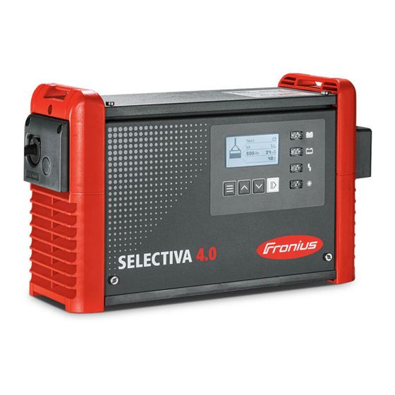
- Page 1 Operating Instructions Selectiva 4.0 2 - 3 kW EN-US Operating instructions 42,0426,0357,EA 008-10052022...
-
Page 3: Table Of Contents
Table of contents Power categories General 2 kW 3 kW Safety Instructions General Environmental conditions Grid connection Dangers due to Grid and Charging Current Danger due to Acids, Gases, and Vapors General information on working with batteries Personal Protection and Protection of Others Safety Measures in Normal Operation EMC device classifications EMC Measures... - Page 4 Additional functions General options Reset settings USB mode Status codes Options Safety 3 kW electrolyte circulation External start/stop Temperature-controlled charging LED strip Air filter Wall and floor bracket "Mobile" set Option box Mounting plate Remote control system Gateway Link Gateway Technical data Selectiva 2 kW Selectiva 3 kW...
-
Page 5: Power Categories
Power categories General The kW specification for the power categories refers to the housing design and is not directly related to the actual device power. 2 kW Selectiva 2040 / 2050 / 2060 / 2070 4020 / 4035 3 kW Selectiva 2080 / 2100 / 2120 4045 / 4060... -
Page 6: Safety Instructions
Safety Instructions General The device has been manufactured using state-of-the-art technology and ac- cording to recognized safety standards. If used incorrectly or misused, however, it can cause injury or death to the operator or a third party damage to the device and other material assets belonging to the operating company inefficient operation of the equipment All persons involved in the commissioning, operation, maintenance, and servicing... -
Page 7: Dangers Due To Grid And Charging Current
IMPORTANT! Ensure secure grounding of the grid connection. Dangers due to Work with battery charging systems poses a number of dangers, such as: Grid and Char- electrical hazard due to grid and charging current. ging Current hazardous electromagnetic fields that may pose a risk of death for individu- als with pacemakers. -
Page 8: Personal Protection And Protection Of Others
Personal Protec- Keep persons, especially children, away from the device and working area during tion and Protec- operation. If persons are in the vicinity, however: tion of Others inform them of any dangers (hazardous acids and gases, risk due to grid and charging current, etc.) provide suitable protective equipment Before leaving the working area, ensure that no personal injury or property dam-... -
Page 9: Data Backup
Data backup The user is responsible for backing up any changes made to the factory settings. The manufacturer accepts no liability for any deleted personal settings. Maintenance Check the mains plug, mains cable, charging lead, and charging terminals for damage before each commissioning. If dirt accumulates on the device, clean the surface of the device housing with a soft cloth and only with solvent-free cleaning agents. -
Page 10: Copyright
Copyright Copyright of these Operating Instructions remains with the manufacturer. Text and illustrations were accurate at the time of printing. Fronius reserves the right to make changes. The contents of the Operating Instructions shall not provide the basis for any claims whatsoever on the part of the purchaser. If you... -
Page 11: General Information
General information Explanation of DANGER! Safety Instruc- tions Indicates an immediate danger. ▶ Death or serious injury may result if appropriate precautions are not taken. WARNING! Indicates a possibly dangerous situation. ▶ Death or serious injury may result if appropriate precautions are not taken. CAUTION! Indicates a situation where damage or injury could occur. -
Page 12: Grid Connection
WARNING! Danger from unsuitable batteries connected to the battery charger. Serious personal injury and property damage as a result of escaping gases, igni- tion or explosion may result. ▶ Only connect batteries to the battery charger which are suitable for the bat- tery charger in terms of their type, voltage and capacity and which corres- pond to the settings on the battery charger. -
Page 13: Charging Cables
Charging cables WARNING! Danger due to charging cables lying around. This can result in severe personal injury and damage to property. Personnel can get caught or trip on unplugged, loose cables ▶ Lay charging cables so that no one can trip over them or get caught on them. WARNING! Danger if the active charging process is interrupted by disconnecting the char- ging plug. -
Page 14: Warning Notices On The Device
AC max. DC nom. DC max. IP21 Protective class I Fronius International GmbH Froniusstraße 1 4643 Pettenbach Austria Dispose of old devices in accordance with safety rules and not in nor- mal domestic waste. Keep potential sources of ignition such as fire, sparks, and open flames away from the battery. -
Page 15: Warning Notices Inside The Device
Warning notices WARNING! inside the device Danger of electric shock. This may result in serious injuries or death. ▶ The housing may only be opened by service technicians trained by the manu- facturer. ▶ Before working with the housing open, the device must be disconnected from the grid. - Page 16 The permissible operating position of the device is horizontal. The ambient air surrounding the device must be kept free from battery acid va- pors as far as possible. Mounting the device directly above the battery to be charged should therefore be avoided. Cooling air The device must be set up so that cooling air can flow through the housing open- ings provided unhindered.
-
Page 17: Wall And Floor Mounting
Wall and floor WARNING! mounting Danger from incorrectly performed work and falling equipment. This can result in severe personal injury and damage to property. ▶ The mounting must only be carried out by trained and qualified personnel. ▶ Follow the safety rules in the Operating Instructions of the battery charger. Depending on the substrate, different dowels and screws are required. - Page 18 341 (13.43) 110 (4.33) 38 (1.5) 123,5 (4.86) 91,5 (3.6) 182 (7.17) 220 (8.66) 123 (4.84) 11 (.43) 266 (10.47) 2 kW (B1) mm (in.) 8.5 (.33)
- Page 19 110 (4.33) 417 (16.42) 38 (1.5) 123,5 (4.86) 182 (7.17) 123 (4.84) 38 (1.5) 220 (8.66) 40 (1.57) 89,5 (3.52) 11 (.43) 342 (13.46) 3 kW (C1) mm (in.) 8,5 (.33)
-
Page 20: Operating Controls And Connections
Operating controls and connections Operating con- trols and con- nections Function USB port The USB port supports a device update and the recording of the charging parameters during the charging process via USB thumb drive. Position for options - External start/stop option - Temperature-controlled charging option (-) Charging cable (+) Charging cable... -
Page 21: Pin Assignment For 2 Kw Optional Plug
Function Control panel LED strip option Lights up in the appropriate col- ors depending on the state of charge, according to the indic- ators explained in the "Control panel" section Cover for optional plug and charging cables The optional plug and the char- ging cables are only accessible by removing the cover (9). - Page 22 Plug Function Plug Function code code Dete Detect wire white C2 G CAN 2GND wire brown C1 G CAN 1GND 13 V 13 V wire white wire brown Power Sup- Remote Control wire Remote Control wire 1 Option Box wire Option Box wire brown white...
-
Page 23: Pin Assignment For 3 Kw Optional Plug
Pin assignment 14-pin optional plug inside the hous- Plug Plug Plug for 3 kW optional Code Code plug Dete C2 G C1 G 13V O C1 L C2 L C1 H C2 H - St + St... - Page 24 Plug Function Plug Function code code Status 1 Dete Detect wire white Status 2 C2 G CAN 2GND wire brown C1 G CAN 1GND 13 V 13 V wire white wire brown Power Sup- Remote Control wire Remote Control wire Option Box wire Option Box wire brown...
-
Page 25: Control Panel
Control panel Function Display Display of the current charging parameters. Display of settings. "Menu" button Select the desired menu. Return to the higher-level selection. "Up/Down" buttons Select the desired menu item. Set the desired value. "Pause/Start" button Pause and resume the charging process. Confirm a menu item or setting. - Page 26 Flashes briefly every 3s: The device outputs a warning. Charging paramet- ers are unfavorable, but charging continues. The display alternately shows the corresponding status code and the state of charge. "Charge" indicator (yellow) Lights up: during charging. Flashes: when the charge has been interrupted. "Battery is charged"...
-
Page 27: Charging The Battery
Charging the battery Starting for the When the battery charger is connected to the grid for the first time, the device is first time in SETUP mode. In this mode, the following basic settings must be made or confirmed: Language (English, German, French, ...) Date, time and time zone Charging cable length and charging cable cross-section Type of battery, curve, number of cells and charging time or battery capacity... -
Page 28: Charging Process
Use the "Up/Down" buttons to set the appropriate charging cable length. Confirm with the "Pause/Start" button. The battery charger is configured with the correct charging cable length ac- cording to the order. An incorrectly set charging cable length can have a negative effect on the charging process! Use the "Up/Down"... - Page 29 WARNING! Danger due to incorrect type of battery and incorrect charging settings. This can result in severe personal injury and damage to property. ▶ Before starting the charging process, make sure that the correct type of bat- tery is set on the battery charger. ▶...
-
Page 30: Interrupting The Charging Process
The battery symbol indicates the current state of charge. The more bars are dis- played, the further the charging process has progressed. As soon as the battery is fully charged, a minute counter appears (figure on the right). This counts the minutes since the end of charging and makes it easier to judge which battery has cooled down the most when using several battery chargers. -
Page 31: Ending The Charging Process
As long as a battery is connected to the battery charger, the charging process can only be interrupted and resumed by pressing the "Pause/Start" button. It is only possible to change the display modes with the "Menu" button, as described in the "Display"... - Page 32 Disconnect the charging plug. When the charging contacts are open, the automatic open-circuit detection en- sures that the charging contacts are voltage-free.
-
Page 33: Display
Display Overview of dis- The device has the following display modes: play modes Function Standard mode In standard mode, the display shows the charging parameters. Statistics mode Visualizes the frequency of the operating states of the device and shows the total number of charges, as well as an overview of the abso- lute and average Ah delivered and energy consumed per charge. -
Page 34: Menu Selection
In standard mode, the display shows the battery charger parameters: Type of battery (e.g., Pb-WET) Charging characteristic (e.g., IUI) Nominal voltage (e.g., 48 V) Capacity (e.g., 300 Ah) Weekday, date and time The battery charger parameters are individually adjustable. Detailed information can be found in the "Configuration mode"... -
Page 35: History Mode
The display of the consumed energy is intended as a guide value and may deviate from the actual amount of energy by up to 5% at the rated power. The deviation may be higher at lower power. History mode History mode provides information regarding the parameters of all stored char- ging processes. -
Page 36: Configuration Mode
Symbol with number Error issued, with code for the corresponding status code. Detailed in- formation can be found in the "Status codes" section. Button symbol with check mark Charge was correctly ended with the "Pause/Start" button. Button symbol with cross Charge was ended without pressing the "Pause/Start"... - Page 37 General options: Language Contrast Time (hh:mm:ss) Time zone Daylight saving time/standard time Date (dd:mm:yy) Charging cable length (m) Charging cable cross-section (mm AC current consumption Unit for temperature values Code for entering the configuration menu activated/deactivated. Time interval for the parameters logged on the USB thumb drive (s). Reset statistics Reset history Reset Settings...
- Page 38 Confirm the entry with the "Pause/Start" button. The selection of the main menu items for configuration mode appears. When selecting a menu item, you may be prompted to read the Operating In- structions. Confirm this prompt by pressing the "Pause/Start" button again.
-
Page 39: Settings
"RI" curve - the "Ah" section is replaced by a setting option for the "Charging time". Both the start and end can be set for the charging time. If required, the start time can be deselected; then the charging time is based exclusively on the spe- cified end of charge following a manual charge start. -
Page 40: Electrolyte Circulation
The individual selection options are explained in detail below. Electrolyte cir- Electrolyte circulation "Air Pump"(not culation available with the Selectiva 220 V ver- sion): The sequential control of the electro- lyte circulation takes place via the bat- tery charger control unit. Several se- lection options are available for this purpose. -
Page 41: Temperature-Controlled Charging
Program ON 1 OFF 1 Repeat ON 2 OFF 2 30 min 25 min 5 min 25 min 3 min 10 min 3 min 20 min 3 min 12 min 3 min 12 min 5 min 10 min 5 min 20 min 2,5 min 7,5 min... -
Page 42: Equalizing Charge
If a curve is selected that requires an external temperature sensor, a mes- sage appears. Confirm the message by pressing the "Pause/Start" button. Equalizing Equalising charge charge No equalizing charge takes place. delay If the battery remains connected to the battery charger for the duration of the set equalizing charge delay ("equalize charge delay"), a special form of charging takes place. -
Page 43: Delay
Delay delay charge start delay Delay time (minutes) between the activation time of the charge start and the actual charge start. charge end delay Delay time (minutes) between the signaled end of charge (e.g. green indicat- or) and the actual end of charge. at mains failure restart charging If this option is activated, the charging process is automatically restarted after a fault in the electrical network as soon as the electrical network is... - Page 44 "Day setting 1-5": The day settings allow up to 5 different charge start time profiles to be defined, with the following setting op- tions: Symbol for curve 1: Time window within which curve 1 should be started (e.g.: 0:00-6:00) Stop: Time window within which no char- ging should take place (e.g.: 6:00-20:00)
-
Page 45: Special Charges
"Year setting": It is possible to assign a week set- ting to several calendar periods (e.g. 1.1. - 7.1.). When the calendar function is activ- ated, a calendar symbol (here with the number "4" as the current date) ap- pears in the display. Special charges Special Charges The "Special Charges"... -
Page 46: Special Function - Opportunity Charging
Special function Special function - Opportunity Charge - opportunity charging In order to extend the operating inter- val of the battery, it is possible, for ex- ample, to recharge the battery during a break in operation. The following curve settings are pos- sible: "Curve"... -
Page 47: Additional Functions
If problems occur with the DC connec- tion during the charging process, status code 17 is set when Check DC- Connection is active. A connection problem can occur, for example, if the charging contacts are worn or dirty. Additional func- Detailed explanation of the "Additional functions"... - Page 48 When "OFF" is set, the refill request does not have to be confirmed. Option Section Option Section 1 Setting options: CAN1 (option box) Cool Bat Guide Easy (Fronius variant only) Option Section 2 (3 kW only) Setting options: CAN2 (option box) Air-Puls (EUW)
-
Page 49: General Options
at mains failure restart charging If this option is activated, the charging process is automatically restarted after a fault in the electrical network as soon as the electrical network is available again. General options Detailed explanation of the "General options" menu item in configuration mode. Select the "General options"... -
Page 50: Reset Settings
The minimum and maximum values differ for the different device classes. The minimum value is ap- prox. 25% of the maximum nomin- al current of the device concerned. Temperature: Temperature in °C/°F Code: Code entry required/not required to enter configuration mode ("Code ON/ OFF") USB Logging Time: Time interval for the charging... -
Page 51: Usb Mode
32 Gigabyte maximum No multiple partitioning I-SPoT-VIEWER software (www.fronius.com/i-spot) supports the visualiza- tion and evaluation of the data on the USB thumb drive. Only plug in the USB thumb drive when no charging process is taking place or the charging process has been interrupted. -
Page 52: Status Codes
The logged data is saved in the same way as for the "Download", but as "csv" files rather than in the I-SPoT VIEWER format. (Automatically created folder structure for the ".csv" files: * Fronius\<Device serial number>\Charges\<yyyymmdd>\<hhmmss.csv>) Save events. Events are saved on the USB thumb drive. - Page 53 If an error message appears on the display and the error cannot be rectified in- dependently: Note down the displayed status code: e.g., "Statecode (31)". Note the configuration of the device. Contact your authorized Service Partner. If the device is in an error state, a freely defined text can be displayed, which can contain the contact details of the distributor, for example.
- Page 54 (57) Message time limit exceeded (58) Login failed Status codes in the event of a gateway error Cause / Remedy (101) CAN Connect setting is active and no CAN connection could be estab- lished to the gateway for at least 2 minutes. (102) Gateway has no connection to the back-end.
- Page 55 (528) High charge relay switched off during load operation (530) Communication problem (532) Microcontroller error (e.g., division by 0) (533) Reference voltage out of tolerance (534) Startup problem (535) PFC overcurrent (536) Phaseshifter or PFC faulty Status codes in the event of an error in the secondary circuit Cause / Remedy (520) Secondary temperature sensor defective (521) Secondary overtemperature...
- Page 56 (547) Load/save settings failed (548) Load/save curve settings failed (549) Charge could not be continued after a power failure (550) Time not set (551) Hardware change detected (552) Configuration memory block invalid (553) Primary update failed (554) Master-slave communication faulty (555) Incorrect device software (557) Interruption of the InterLock communication (558) The second device, which is connected via the InterLock, has an error...
-
Page 57: Options
Options Safety In order to connect optional components, it may be necessary to open the hous- ing. Observe the following warnings: WARNING! Danger of electric shock. This may result in serious injuries or death. ▶ The housing must never be opened by anyone other than a service technician trained by the manufacturer. - Page 58 NOTE! Danger due to non-compliance with the permissible mains voltage tolerance. Malfunctions and damage to property may result. ▶ For the electrolyte circulation option, a limited mains voltage tolerance of 207 V to 250 V applies compared to the battery charger. The electrolyte circulation option delivers air into the battery via specially de- signed capillary tubes.
-
Page 59: External Start/Stop
mm (in.) 464 (18.27) 110 (4.33) External start/ The external start/stop option prevents spark formation at the charging plug if it stop is disconnected during charging. Special contacts inside the charging plug re- gister a disconnection from the charging socket. These contacts are leading in comparison to the main contacts. -
Page 60: Air Filter
Air filter In dusty environments, the air filter prevents contamination of the inside of the device. This prevents any reduction in performance or other impairment of the device. Detailed information can be found in the corresponding User Information. Cleaning interval as required (manufacturer's recommendation: monthly) Wall and floor The robust wall and floor bracket with integrated cable holder ensures safe in- bracket... -
Page 61: Remote Control System
mm (in.) 482 (18.98) 115 (4.53) 425 (16.73) 428 (16.85) 456 (17.95) 462 (18.19) 415 (16.34) 418 (16.46) 446 (17.56) 3 kW (C1) 452 (17.80) Remote control The remote control system allows full operation of the device from a distance of system up to 30 m (98 ft., 5.1 in.). -
Page 62: Technical Data
Technical data Selectiva 2 kW WARNING! An electric shock due to a residual current can be fatal. Only use a type B residual current circuit breaker for the grid connection of the device. ~ 230 V, ± 15% Mains voltage Mains frequency 50/60 Hz max. -
Page 63: Selectiva 3 Kw
Device-specific Max. AC Max. AC Nominal Max. Weight data current power voltage charging current 2040 2kW 7.9 A 1540 W 24 V 40 A 5.8 kg (12.79 lb.) 2050 2kW 9.9 A 1930 W 24 V 50 A 6.1 kg (13.45 lb.) 2060 2kW 12.0 A... - Page 64 Relative humidity max. 85% Maximum altitude above sea level 2000 m (6561 ft.) Mark of conformity According to rating plate Product standard EN62477-1 The device may be operated on grids that are grounded at the neutral point. The thermal rating of the automatic circuit breaker must not exceed 30,000 A Interface to a 230/400 V and 50 Hz public grid.
Need help?
Do you have a question about the Selectiva 4.0 2040 and is the answer not in the manual?
Questions and answers