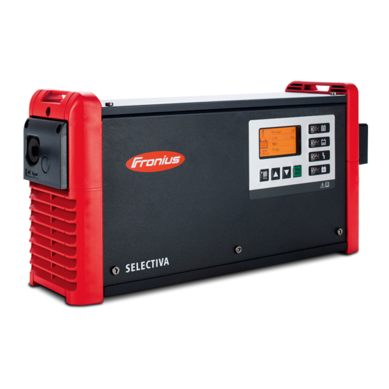
Fronius Selectiva 2040 2kW Operating Instructions Manual
Battery charging system
Hide thumbs
Also See for Selectiva 2040 2kW:
- Operating instructions manual (46 pages) ,
- Service manual (64 pages)
Table of Contents
Advertisement
Quick Links
/
Perfect Charging
/ Perfect Welding / Solar Energy
Selectiva 2040 2kW
Selectiva 2050 2kW
Selectiva 2060 2kW
Selectiva 2070 2kW
Selectiva 2080 3kW
Selectiva 2100 3kW
Selectiva 2120 3kW
Selectiva 4020 2kW
Selectiva 4035 2kW
Selectiva 4045 3kW
Selectiva 4060 3kW
42,0426,0226,EN 005-21022019
Operating Instructions
Battery charging system
Advertisement
Table of Contents


Need help?
Do you have a question about the Selectiva 2040 2kW and is the answer not in the manual?
Questions and answers