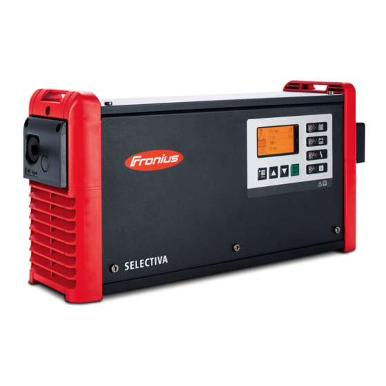
Fronius Selectiva 2040 2kW Service Manual
Battery charging system
Hide thumbs
Also See for Selectiva 2040 2kW:
- Operating instructions manual (46 pages) ,
- Operating instructions manual (60 pages)

Subscribe to Our Youtube Channel
Related Manuals for Fronius Selectiva 2040 2kW


Summary of Contents for Fronius Selectiva 2040 2kW
- Page 1 Perfect Charging / Perfect Welding / Solar Energy Service manual Selectiva 2040 2kW Selectiva 2050 2kW Battery charging system Selectiva 2060 2kW Selectiva 2070 2kW Selectiva 4020 2kW Selectiva 4035 2kW 42,0426,0264,EN 013-22082018...
-
Page 3: Table Of Contents
Contents General information Foreword and safety instructions ....................... Safety..............................Protective measures against ESD ......................Fronius Technical Support ........................Ordering spare parts ..........................Service manual contents........................Tools and measuring devices ....................... Changing components .......................... Safety inspection........................... Appendix ............................... Tools and measuring devices ........................ - Page 4 Safety Inspections Safety Inspections............................Safety inspection........................... Responsibility............................Area of application ..........................Inspection staff qualifications ........................ Measuring instruments.......................... Visual inspections ............................General ..............................Mains supply and connecting lines ....................... Housing and covers ..........................Adjustment and display devices......................Rating plate and warning stickers ......................Electrical tests............................
-
Page 5: General Information
General information... -
Page 7: Foreword And Safety Instructions
Please contact your national Fronius Technical Support team with any fault analysis que- Support ries. Ordering spare Please contact your national Fronius Technical Support team to order spare parts or to parts consult on fault analysis queries. Service manual Each chapter in the service manual deals with one complete topic. Use each chapter as a contents self-contained source of information. -
Page 8: Safety Inspection
Please also be aware of the requirements and standards relevant to your country, as the measured values or steps taken during the tests may vary. Should there be no relevant requirements and standards in your country, Fronius recom- mends that this test should still be carried out. -
Page 9: Tools And Measuring Devices
Tools and measuring devices General "Tools and measuring devices" offers an overview and description of all equipment needed to service the device professionally. This equipment includes: Tools required Measuring and testing equipment Ancillary materials Tools required Torx screwdriver, TX20 Torx screwdriver, TX25 Slotted screwdriver, 3 mm Slotted screwdriver, 6.5 mm Cross-head screwdriver PH2... -
Page 10: Function Overview
Warning notices A number of safety symbols can be seen on the charger's rating plate. The safety sym- on the device bols must not be removed or painted over. Selectiva xxxx www.fronius.com Part No.: 4,010,xxx Ser. No.: xxxxxxxx xxxxxxxx 1~ NPE 230V 50/60Hz AC nom. -
Page 11: Warning Notices Inside The Device
Warning notices WARNING! An electric shock can be fatal. The housing must never be opened inside the device by anyone other than a service technician trained by the manufacturer. The de- vice must be disconnected from the mains before starting any work with the hous- ing open. -
Page 12: Control Panel
Control panel Function Display Displays the current charging parameters Displays settings "Menu" key Selects the desired menu Selects the appropriate symbol to return to the previous display Up/down keys Select the desired menu item Set the desired value Stop/Start key For interrupting and resuming the charging process Confirms a menu item or setting "Battery cooled down"... - Page 13 "Charge" indicator (yellow) On: During charging Flashes: If charging has been interrupted "Battery charged" indicator (green) On steady: Charging ended. Flashes every second: Charging ended. The water refill indicator has also tripped.
-
Page 15: Error Location Aid
Error location aid... -
Page 17: Service Codes
Service codes Safety WARNING! An electric shock can be fatal. Before opening the device: Unplug the device from the mains Disconnect the device from the battery Using a suitable measuring device, ensure that electrically charged compo- nents (e.g. capacitors) are fully discharged Restrict access to the working area Take steps to ensure the metallic surfaces of the device cannot be touched Suitable protective clothing and/or equipment must be worn when carrying... - Page 18 Cause: Buttons not working Remedy: Check wiring Replace the display Replace power module Status codes caused by external factors: Cause: Mains undervoltage or overvoltage Remedy: Check whether the mains voltage is within the permitted range Replace power module Cause: External temperature sensor faulty Remedy: Check wiring and temperature sensor Replace power module...
- Page 19 Cause: Battery too cold (external temperature sensor only) Remedy: Check battery and if necessary, place in a suitable environment Check device settings (check limit values) Replace power module Cause: Cell fault detected (RI characteristic) Remedy: Check battery - measure voltage of individual cells > faulty battery Check battery for parallel loads - change characteristic if necessary Replace power module Cause: Battery is connected with reverse polarity...
- Page 20 Status codes in the event of a device fault / primary circuit: Cause: Primary temperature sensor faulty Remedy: AC reset (restart device) Replace power module Cause: Primary overtemperature Remedy: Check device location Check ambient temperature Clean fan Replace power module Cause: Ventilator current outside the tolerance Remedy: Clean fan...
- Page 21 Cause: Reference voltage outside the tolerance Remedy: Software update Replace power module Cause: Start-up error Remedy: Disconnect device from mains for 5 mins Software update Replace power module Cause: PFC overcurrent Remedy: AC reset (restart device) Software update Replace power module Cause: Phase shifter or PFC faulty Remedy: AC reset (restart device)
- Page 22 Cause: Secondary SELV communication not working Remedy: AC reset (restart device) Software update Replace power module Cause: EEPROM faulty / access not working Remedy: AC reset (restart device) Replace power module Cause: Microcontroller - fault (e.g.: division by 0) Remedy: AC reset (restart device) Software update Replace power module...
-
Page 23: Customer Service
Resets device to factory setting Software update Replace power module Customer service IMPORTANT! Contact your Fronius dealer or a Fronius-trained service technician if an error appears frequently or all the time an error appears that is not listed in the tables... -
Page 25: Changing Components
Changing components... -
Page 27: General
General Safety WARNING! An electric shock can be fatal. Before opening the device: Turn the main device switch to the OFF position Disconnect the device from the mains and the battery Put up an easy-to-understand warning sign to stop anybody inadvertently switching it back on again Using a suitable measuring instrument, check to make sure that electrically charged components (e.g. -
Page 28: Opening The Device
Opening the device Opening the Se- lectiva NOTE! Remove the LED diffuser strips (1), if present Undo the two 4x10 TX20 screws (2) Undo the four 4x10 TX20 screws (3) and remove the housing cover (4) - Page 29 Disconnect the display (5) and LED strips (6), if present. Bend the groun- ding lug (7) upwards. Undo the two 4x10 TX20 screws (8) and remove the front of the housing (9) Remove the insulating sheet (10) (10)
-
Page 30: Replacing The Display
Replacing the display Replacing the Removing the graphic display: graphic display Remove the front of the housing (see "Opening the device") Undo the three 4x9 TX20 tapping screws (1) Take the graphic display out of the dis- play spacer frame Ensure that the insulating sheet (2) between the display and front panel is not removed... -
Page 31: Replacing The Mains Cable
Replacing the mains cable Replacing the Removing the mains cable: mains cable Remove the two 4x20 TX20 screws (1) and AC connecting plate (2) Unplug the mains cable (3) from the power module (L1) (PE) Remove the strain-relief device by pressing on the upper and lower lugs (4) and unthreading from the AC connection plate... - Page 32 Open the cover on the strain-relief de- vice (5) by pressing on the sides (6) and remove the mains cable (7). Installing the mains cable: Insert the mains cable (7) into the strain-relief device (6) and close the cover of the strain-relief device (5) with a firm push.
- Page 33 Plug the mains cable (3) into the power module (L1) (PE) Insert the AC connection plate (2) and secure it with the two 4x20 TX20 screws (1). [1.5 Nm]...
-
Page 34: Replacing The Charging Lead
Replacing the charging lead Replacing the Removing the charging lead: charging lead Remove the two 4x20 TX20 screws (1) and remove the DC connection plate (2). Remove the 4x20 TX20 screw (3) and remove the strain-relief device (4) Undo the two M8 (size 13) hexagon nuts (5) Remove the charging lead (6). - Page 35 Installing the charging lead: Thread the new charging lead (10) to the M8 bolts (9) and tighten the nuts (5) by hand. Bolt placement: M8 bolt (9) Cable lug of the charging lead (8) M8 brass washer (7) M8 lock washer (6) M8 hexagon nut (5) WARNING! When fitting the strain-relief device, ensure that...
-
Page 36: Replacing The Fan
Replacing the fan Replacing the axi- Removing the axial fan: al fan Remove the top screw (1) that connects the device frame to the de- vice casing (see the "Opening the de- vice" section) Remove the device frame (mains cable side), then undo the 5x10 TX25 screw (2), push the latches together (3), and lift and remove the device frame (4) - Page 37 Installing the axial fan: Click the fan (6) into the fan holder (7). WARNING! Be careful not to press on the rotor. NOTE! Note the rotational direc- tion of the fan. NOTE! Spin the fan blade to en- sure that the fan spins easily. WARNING! Ensure the fan cable is positioned correctly Click the fan holder (7) including the...
-
Page 38: Changing The Internal Battery
Changing the internal battery Changing the in- Removing the battery: ternal battery Remove the housing (see "Opening the housing") (1) (2) Push the battery locking device (1) to the left and remove the battery (2). Installing the battery: Install the battery (2) with the correct polarity and ensure that the locking de- (1) (2) vice (1) snaps into place. -
Page 39: Replacing The Power Module
Replacing the power module Replacing the Removing a power module: power module Remove the housing (see "Opening the device") Remove the mains cable including the side panel (see "Replacing the fan") Remove the fan including the fan hol- der (see "Replacing the fan") Remove two 5x8 TX25 screws (3) next to the charging leads. - Page 40 Fitting a power module: WARNING! The power module must not be taken out by the elec- trolytic capacitors WARNING! The power module must only be pulled or pushed in at the heat sink end Slide the power module (5) in towards the left.
-
Page 41: Closing The Device
Closing the device Closing the Se- Fit the insulating sheet (10) lectiva (10) Fit the front of the housing (9) and two 4x10 TX20 screws (8) [2,5 Nm] Reconnect the display (5) and LED strips (6), if present. Bend the groun- ding lug (7) into position... - Page 42 Fit the housing cover (4) and four 4x10 TX20 screws (3) [2,5 Nm] Fit two 4x10 TX20 screws (2) [2,5 Nm] NOTE! Insert the LED diffusor strips (1), if present, by pressing on them...
-
Page 43: Safety Inspections
Safety Inspections... -
Page 45: Safety Inspections
Please also be aware of the requirements and standards relevant to your country, as the measured values or steps taken during the tests may vary. Should there be no relevant requirements and standards in your country, Fronius recom- mends that this test should still be carried out. - Page 46 Insulation resistance The measuring voltage value shown on the measuring device must be at least the same as the rated voltage to earth of the device to be tested, however it must be no less than 500 V DC voltage. The measuring current must be at least 1 mA (this corresponds to a load resistance of 0.5 M).
-
Page 47: Visual Inspections
Visual inspections General The following must be visually inspected without any further dismantling of the device. Ob- vious defects in any safety-related device components are unacceptable. Defects that could pose a risk during the visual inspection must also be recorded. Any defects that could cause other hazards must be repaired immediately or restrictions placed on the further use of the system until repairs have been effected. -
Page 48: Electrical Tests
Electrical tests Ground conduc- The device to be tested must be safely isolated from the AC mains supply. The mains tor resistance lead (L1, N, PE) must not be connected. Follow the safety rules. The device to be tested must be safely isolated from the battery. The charging leads must not be connected. - Page 49 The main switch must be switched on. With nominal (DC) battery charging system voltages 500 V the test voltage of the measuring device is 500 V for all measurements *). The insulation resistance must not fall below the following values *): Measurement Measurement value ...
-
Page 50: Ground Conductor Current
WARNING! An electric shock can be fatal. Capacitors can charge during the in- sulation resistance measurement. After carrying out the insulation resistance measurement, check that all tested potentials are de-energised before continuing with the safety inspection. Alternatively, the capacitors can be discharged by short-circuiting the tested potentials or via the discharge function on the insulation tester. - Page 51 1 Measuring device 2 Battery charging system 8 Isolated setup of test piece Example: measuring ground conductor current th- 9 Measuring line rough ground conductor directly on the battery char- ging system Differential current method - Ground conductor current measured using an ammeter on the N and L conductors 1 Measuring device 2 Battery charging system...
-
Page 52: Contact Current
Contact current The following points must be observed during the contact current measurement: Do not perform the measurement until the ground conductor current measurement has been carried out successfully The device must be in charge mode The measurement is taken between a grounded point and the conductive part that can be touched and that is not connected to the ground conductor. -
Page 53: Function Tests
Function tests General In the event a repair is needed, the Service menu is required to: Recover the serial number Perform function tests Acknowledge status code 551 (which is shown after a power module replacement) If a Z power module is installed, a hardware change is detected and the error "551 - hardware change detected"... -
Page 54: Function Tests In The Service Menu
If the serial number does not match the checksum, an "X" is displayed next to "Sa- ve" and it must be entered again If the serial number matches the checksum, the Service menu is displayed. The Service menu comprises two subme- nus: Device tests Options tests... - Page 55 The Service menu comprises two subme- nus: Device tests Options tests "Device tests" consists of three tests: Fan Test Current Test (charging current measu- rement) Voltage Test (output voltage measure- ment) Fan Test: To start the fan test, the Fan item must be set to "ON".
-
Page 56: Other Function Tests In The Service Menu
A tick appears next to the menu item once the test has been completed Measuring the output voltage: Stop short-circuiting the charging leads The device must be operated in open circuit Prepare the output voltage measure- ment Voltage Test "ON" Info: the output voltage is displayed for checking purposes A tick appears next to the menu item once... -
Page 57: Mains Power On/Off Equipment
Mains power on/ Evidence of proper operation must be provided by measurement or visual inspection. off equipment AC and DC disconnection inspection (performed under no load) AC disconnection battery charging system must switch off DC disconnection battery charging system must stop charging Switch on AC and DC The correct operation of the indicators and controls must be checked. -
Page 58: Documentation
Any device that fails a test must be clearly marked as unsafe and the operator in- formed. The device may no longer be used. The test record for the "Safety inspection" is available on the Fronius Partnerweb. -
Page 59: Appendix
Appendix... -
Page 60: Circuit Diagrams: Selectiva 1~ 2Kw
Circuit diagrams: Selectiva 1~ 2kW... - Page 64 Fronius Worldwide - www.fronius.com/addresses Fronius International GmbH Froniusplatz 1 A-4600 Wels E-Mail: perfect.charging@fronius.com http://www.fronius.com Under http://www.fronius.com/addresses you will find all addresses of our sales branches and partner firms!
Need help?
Do you have a question about the Selectiva 2040 2kW and is the answer not in the manual?
Questions and answers