Table of Contents
Advertisement
Quick Links
Advertisement
Table of Contents

Related Manuals for turck NCLS Series


Summary of Contents for turck NCLS Series
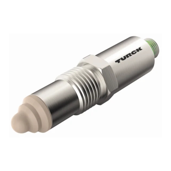
- Page 1 Your Global Automation Partner NCLS… Limit Level Sensor Instructions for Use...
- Page 2 Hans Turck GmbH & Co. KG | T +49 208 4952-0 | F +49 208 4952-264 | more@turck.com | www.turck.com...
-
Page 3: Table Of Contents
Installing the welding adapter.................... 13 Connection............................ 14 Wiring diagrams ...................... 14 Commissioning .......................... 15 Operation ............................ 16 LEDs.......................... 16 Setting .............................. 17 10 Troubleshooting .......................... 18 11 Maintenance............................ 19 12 Repair.............................. 19 12.1 Returning devices...................... 19 13 Disposal .............................. 19 14 Technical data ........................... 20 15 Turck subsidiaries — contact information .................. 22 V01.01 | 2022/06... - Page 4 Contents Hans Turck GmbH & Co. KG | T +49 208 4952-0 | F +49 208 4952-264 | more@turck.com | www.turck.com...
-
Page 5: About These Instructions
This symbol denotes actions that the user must carry out. RESULTS OF ACTION This symbol denotes relevant results of actions. Other documents Besides this document, the following material can be found on the Internet at www.turck.com: Data sheet Declarations of conformity (current versions) Commissioning manual IO-Link devices... -
Page 6: Notes On The Product
CAD files in numerous export formats. The contact details of Turck subsidiaries worldwide can be found on p. [} 22]. Hans Turck GmbH & Co. KG | T +49 208 4952-0 | F +49 208 4952-264 | more@turck.com | www.turck.com... -
Page 7: For Your Safety
The product is designed according to state-of-the-art technology. However, residual risks still exist. Observe the following warnings and safety notices to prevent damage to persons and property. Turck accepts no liability for damage caused by failure to observe these warning and safety notices. -
Page 8: Product Description
IO-Link interface, thus enabling direct access to the process values and parameters of the device during normal operation. The device can only be parameterized via IO-Link. Hans Turck GmbH & Co. KG | T +49 208 4952-0 | F +49 208 4952-264 | more@turck.com | www.turck.com... -
Page 9: Technical Accessories
Technical accessories 4.5.1 Mounting accessories Dimension drawing Type Description NCLS-WA0 100004429 Process adapter, cylindrical welding sleeve without control bore for capacitive NCLS limit level sensors, 20 [0.79] suitable for hygienic applications, material 316L, max. Ø 30 [1.18] temperature 140 °C Ø 16 [0.63] G1/2 34 [1.34] NCLS-WA1... -
Page 10: Connection Accessories
Connection cable, M12 female connector, straight, 4-pin, stainless steel coupling nut, cable length: 2 m, jacket material: TPE, gray; temperature range: -40… +105 °C Hans Turck GmbH & Co. KG | T +49 208 4952-0 | F +49 208 4952-264 | more@turck.com | www.turck.com... -
Page 11: Installing
„ Always mount the sensor with the process adapter. „ Only use a Turck process adapter for the process connection. A Turck process adapter must be used for the process connection. The process adapter is avail- able as a clamp adapter, welding adapter or screw-in adapter. -
Page 12: Mounting The Sensor With The Process Adapter
Install the leakage hole (A) so that it is clearly visible. When using vertical cables, the leak- age hole must face downward. Hans Turck GmbH & Co. KG | T +49 208 4952-0 | F +49 208 4952-264 | more@turck.com | www.turck.com... -
Page 13: Installing The Welding Adapter
5.3.1 Installing the welding adapter „ Proceed as follows to attach the welding sleeve: Fig. 5: Attach the welding sleeve „ If necessary, screw in an auxiliary tool to prevent damage from heat on the welding sleeve. „ Carry out the welding as shown in the following figure. Allow for a reasonable time between the welding seams in order to avoid heat damage. -
Page 14: Connection
Connect the device as shown in the wiring diagram. Wiring diagrams out 2: switch out 1: switch/IO-Link – Fig. 7: Pin assignment Fig. 8: Wiring diagram Hans Turck GmbH & Co. KG | T +49 208 4952-0 | F +49 208 4952-264 | more@turck.com | www.turck.com... -
Page 15: Commissioning
Commissioning After connecting and switching on the power supply, the device is automatically ready for op- eration. V01.01 | 2022/06... -
Page 16: Operation
The switching state of output 2 (OUT2) cannot be indicated via an LED. Green flashing Process value within the set hysteresis Hans Turck GmbH & Co. KG | T +49 208 4952-0 | F +49 208 4952-264 | more@turck.com | www.turck.com... -
Page 17: Setting
Setting The device can only be parameterized via IO-Link. The following settings are possible for each output: Output type: PNP, NPN, push-pull Output function: NO contact (NO), NC contact (NC), pulse width modulation (PWM) Switching hysteresis (at least 2 %) Time delay for the switching signal Parameter setting via IO-Link is explained in the IO-Link commissioning manual. -
Page 18: Troubleshooting
If there are no faults, there is a device malfunction. In this case, decommission the device and replace it with a new device of the same type. Hans Turck GmbH & Co. KG | T +49 208 4952-0 | F +49 208 4952-264 | more@turck.com | www.turck.com... -
Page 19: Maintenance
Observe our return acceptance conditions when returning the device to Turck. 12.1 Returning devices Returns to Turck can only be accepted if the device has been equipped with a Decontamination declaration enclosed. The decontamination declaration can be downloaded from https://www.turck.de/en/retoure-service-6079.php and must be completely filled in, and affixed securely and weather-proof to the outside of the packaging. -
Page 20: Technical Data
COM 2/38.4 kbps Process data width 16-bit Measured value information 14 bit Switching point information 2 bit Frame type Contained in SIDI GSDML Hans Turck GmbH & Co. KG | T +49 208 4952-0 | F +49 208 4952-264 | more@turck.com | www.turck.com... - Page 21 NCLS-30-UP6X-H1141 NCLS-30-UN6X-H1141 Mechanical data Design Threaded barrel, G ½” Dimensions 94.8 × 22 × 22 mm Housing material Stainless steel 1.4404 (AISI 316L) Material (in direct contact with Plastic, PEEK media) Max. tightening torque of 20 Nm housing nuts Process connection G ½”...
-
Page 22: Turck Subsidiaries - Contact Information
Turck Banner Malaysia Sdn Bhd Unit A-23A-08, Tower A, Pinnacle Petaling Jaya, Jalan Utara C, 46200 Petaling Jaya Selangor www.turckbanner.my Hans Turck GmbH & Co. KG | T +49 208 4952-0 | F +49 208 4952-264 | more@turck.com | www.turck.com... - Page 23 Mexico Turck Comercial, S. de RL de CV Blvd. Campestre No. 100, Parque Industrial SERVER, C.P. 25350 Arteaga, Coahuila www.turck.com.mx Netherlands Turck B. V. Ruiterlaan 7, NL-8019 BN Zwolle www.turck.nl Austria Turck GmbH Graumanngasse 7/A5-1, A-1150 Wien www.turck.at Poland TURCK sp.z.o.o.
- Page 24 Over 30 subsidiaries and over 60 representations worldwide! 100021577 | 2022/06 100021577 www.turck.com...
Need help?
Do you have a question about the NCLS Series and is the answer not in the manual?
Questions and answers