Table of Contents
Advertisement
Quick Links
Advertisement
Table of Contents

Related Manuals for ETS NORD EOZ-1


Summary of Contents for ETS NORD EOZ-1
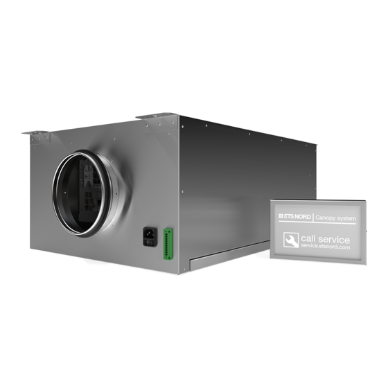
- Page 1 NORDcanopy EOZ – External Ozone Cleaning System Installation Guide...
-
Page 2: Table Of Contents
® NORDcanopy | EOZ installation guide Table of contents Safety notes Installation flowchart 1. Check the product shipment 2. System overview 3. Mount the EOZ 4. Install the Control Panel 5. Electrical Installation 6. Measure and adjust airflow 7. Setting Ozone Module addresses Control Panel display messages Facts about ozone Limited warranty of device... -
Page 3: Safety Notes
• External Ozone Cleaning System uses high voltage to create an electric charge that generates ozone (O₃). Ozone significantly reduces odor, grease, mold and bacteria. ETS NORD AS disclaims any liability in the case that the product is not used in accordance with the manufacturer’s instructions contained in this manual. -
Page 4: Check The Product Shipment
® NORDcanopy | EOZ installation guide 1. Check the product shipment Check that the parcel contains all components listed below and that there is no visible damage. Notify both the freight forwarder and supplier immediately of any damage or missing components. Before installing the device read through the entire instruction material. -
Page 5: System Overview
® NORDcanopy | EOZ installation guide 2. System overview The Ozone Modules within the EOZ chassis produce ozone gas. Ozone (O ) is a very effective oxidant, and when mixed into a kitchen exhaust airstream it breaks down grease and odor particles to water vapor, carbon dioxide and dry minerals, all natural products of oxidation which exit the exhaust system. - Page 6 Voltage Max power Model quantity (mm) (mm) (mm) (kg) (V, Hz) EOZ-1 230/50 EOZ-2 230/50 Ød 12,5 NOTE! Installation may only be carried out by specialist and authorized persons in accordance with local , regional, national standards and regulations. www.etsnord.com...
-
Page 7: Mount The Eoz
® NORDcanopy | EOZ installation guide 3. Mount the EOZ The EOZ unit may be installed in any convenient location in the kitchen space, ideally with easy access to supply air and within 3m of the canopy connection to the exhaust duct. Keep in mind, however, that all duct installation materials between the outlet of the EOZ unit and the main exhaust duct, including screws, rivets and the connecting flange, must be stainless steel (AISI 316). - Page 8 ® NORDcanopy | EOZ installation guide Connect to the ventilation ducts After the EOZ unit has been securely attached to the ceiling, connect the supply air and exhaust air ducts. Note: Materials for the supply air side may be chosen at the discretion of the installer. However, all materials used between the outlet of the EOZ unit and the main exhaust duct, including screws, rivets and the connecting flange, must be stainless steel (AISI 316).
- Page 9 ® NORDcanopy | EOZ installation guide Connect the pressure measurement hose to the exhaust duct NOTE! This hose must be connected between the EOZ unit and main exhaust duct for proper operation. Begin by installing the measurement nozzle onto the exhaust duct or canopy exhaust chamber with a stainless steel rivet or sheet metal screw.
- Page 10 ® NORDcanopy | EOZ installation guide Finally, secure the hose to the duct using adhesive cable tie mounts and cable ties that can found in the EOZ packaging. . NOTE! Be careful not to tighten the cable ties to strongly to ensure that the airflow through the hose is not blocked.
-
Page 11: Install The Control Panel
® NORDcanopy | EOZ installation guide 4. Install the Control Panel Control Panel overview 1 - Anchor points for wall mounts 2 - Data cable bushings 3 - RJ-45 connector Disassembly the control panel Choose a visible and easily accessible location in the kitchen suitable for mounting the Control Panel. - Page 12 ® NORDcanopy | EOZ installation guide Mounting the backplate Before mounting the backplate apply an even strip of waterproof silicone along the rear of the backplate as pictured below. Fasten the backplate to the wall with its cable cutout facing downward, preferably at eye level but not higher than 180 cm from the floor.
-
Page 13: Electrical Installation
® NORDcanopy | EOZ installation guide 5. Electrical Installation NOTE! Electrical installation must be performed by an authorized electrician and follow local, regional and national standards and regulations. The EOZ 3.1 External Ozone Cleaning System must be interlocked with the exhaust system, so that when the exhaust ventilation is not running, no electrical power is supplied to the ozone system. - Page 14 ® NORDcanopy | EOZ installation guide Connecting the main electrical supply Control Panel power cables may be fed through rear wall. Connect the 230V supply cable to the power supply terminals L, N and PE, as shown in the diagram. 230V supply cable Power supply EOZ is supplied with a power cable that can be found inside the packaging.
- Page 15 ® NORDcanopy | EOZ installation guide Control Panel and EOZ data wiring There are three cables that must be connected to the Control Panel. Data cable (3x0,25mm2) for communication between Control Panel and EOZ unit, I/O cable (5x0,5mm²) for connecting to the building automation and LAN cable to access the Control Panel via internet.
- Page 16 3x0,25 mm 3x0,25 mm Control Panel EOZ-2 EOZ-1 nr. 1 EOZ-1 nr. 2 Thus, each A, B+ and C data wire leading in from devices of any EOZ in the chain should share the same terminal screw in its respective connector.
- Page 17 ® NORDcanopy | EOZ installation guide Control panel and I/O cable wiring Next, install the I/O data cable for your building automation system or for future upgrades rout the I/O cable to the junction box. PLC / Building automation Control panel Junction box Connect the five (5) terminals DI1, DI2, DO1, DO2 and COM+ and mark the other ends of the wires within the junction box with their corresponding terminal assignments.
- Page 18 ® NORDcanopy | EOZ installation guide Control panel LAN cable wiring Finally, connect the EOZ system to the local area network, connect the LAN cable to the Control Panel by unplugging the existing short LAN jumper cable inside and connect your LAN cable straight to the port on the board as seen below.
-
Page 19: Measure And Adjust Airflow
Confirm that the system airflow and pressures fall within the following specifications: Operational airflow Pressure difference Pressure drop Model (l/s) (Pa) (Pa) EOZ-1 EOZ-2 Images are for illustrative purposes. RDT-59-0322 We reserve the right to make changes. -
Page 20: Setting Ozone Module Addresses
All Ozone Modules connected to the same Control Panel must be set to a unique device address. The Ozone Module(s) inside of an EOZ chassis have been set at the factory to the following specifications: EOZ-1: Device address is “3” EOZ-2: Device addresses are “1” and “2”... - Page 21 ® NORDcanopy | EOZ installation guide Disconnect cables inside the EOZ Disconnect both the data and power cables from the Ozone Modules inside the EOZ chassis. Remove the OZ module and disconnect the pressure measurement hose Remove the pressure measurement hose from the data connection side. Images are for illustrative purposes.
- Page 22 ® NORDcanopy | EOZ installation guide Next, while supporting each Ozone Module, release its four (4) clamps that fasten it in place. While carefully lowering the module, locate and disconnect the pressure measurement hose from the inside the 100mm exhaust hole.
- Page 23 ® NORDcanopy | EOZ installation guide Assign unique addresses to OZ modules For this procedure a narrow 2mm flat-head screwdriver will be needed. All Ozone Modules connected to a single Control Panel must have a unique device address. Example: Ozone Module one (Address 1): Ozone Module thirteen (Address 13): Switch 1x = 1 Switch 1x = 3...
- Page 24 ® NORDcanopy | EOZ installation guide Next, note the location of each of the pressure nozzles inside the EOZ chassis, and connect the short hoses to their nearest ozone modules as shown below. Cable connections Carefully reinstall all data connectors inside the EOZ chassis to the Ozone Module data and power supply sockets.
- Page 25 ® NORDcanopy | EOZ installation guide Reinstall the bottom panel Finally, reinstall the EOZ bottom panel and secure it with its two (2) clamps. Ensure the panel is sitting flush and is airtight. Remember to reapply power to the unit for operation. Images are for illustrative purposes.
-
Page 26: Control Panel Display Messages
NOTE! Cooking in the kitchen may continue when Control Panel alarm is active as long as there is no sign of ozone. Still service is required and information must be provided to ETS NORD representative or nearest authorized service company www.etsnord.com... -
Page 27: Facts About Ozone
• The new device is covered by a 2-year warranty against defects and manufacturing defects, if: - the initial commissioning of the device has been performed by an authorized partner of ETS NORD AS - the equipment is serviced every 12 months after commissioning - specified components (eg ozone generating equipment) have been replaced as required •... - Page 28 ETS NORD AS Address: Peterburi tee 53 11415 Tallinn Estonia Phone: +372 680 7360 info@etsnord.ee www.etsnord.ee ETS NORD Finland Address: Pakkasraitti 4 04360 Tuusula Finland Phone: +358 401 842 842 info@etsnord.fi www.etsnord.fi ETS NORD Sweden Address: Järsjögatan 7 69235 Kumla...
Need help?
Do you have a question about the EOZ-1 and is the answer not in the manual?
Questions and answers