Table of Contents
Advertisement
Quick Links
Advertisement
Table of Contents

Subscribe to Our Youtube Channel
Related Manuals for Ecler HMA120


Summary of Contents for Ecler HMA120
- Page 1 HMA120 AMPLIFIER Self-powered Media Mixer USER MANUAL 50-0262-0104 HMA120 EN...
-
Page 2: Table Of Contents
INDEX IMPORTANT REMARK......................3 IMPORTANT SAFETY INSTRUCTIONS ................3 IMPORTANT NOTE ........................5 INTRODUCTION ........................5 4.1. Main features: ..........................6 INSTALLATION.......................... 7 AUDIO INPUTS .......................... 8 6.1. MIC1, MIC2/LINE Inputs ......................8 6.2. LINE1, LINE2, LINE3 Inputs ....................9 6.3. -
Page 3: Important Remark
IMPORTANT REMARK The lightning flash with arrowhead symbol, within an equilateral triangle, is intended to alert the user to the presence of uninsulated “dangerous voltage” within the product’s enclosure that may be of sufficient magnitude to constitute a risk of electric shock to persons. The exclamation point within an equilateral triangle is intended to alert the user to the presence of important operating and maintenance (servicing) instructions in the literature accompanying the appliance. - Page 4 9. Do not defeat the safety purpose of the polarized or grounding type plug. A polarized plug has two blades with one wider than the other. A grounding type plug has two blades and a third grounding prong. The wide blade or the third prong are provided for your safety.
-
Page 5: Important Note
5 audio input channels and additional functions to select sound sources and adjust volume from external wall control panels. The HMA120 is a compact professional solution for sound systems when the end user is not necessarily an audio equipment expert since it offers a simple set-up and use. -
Page 6: Main Features
4.1. Main features: • 1 balanced microphone input mixable with the selected music program (MIC1) • 1 balanced microphone/line input mixable with the selected music program (MIC2/LINE) • 3 line inputs for music sources • Integrated audio player (supporting mp3 format) with ports for USB storage media and SD CARD •... -
Page 7: Installation
(micro, line…). This may cause the system to oscillate, damaging the amplifier and speakers. The HMA120 can be installed on a tabletop, in a standard width rack (19") or in a half- width rack (9.5"). Both rack installation options are possible using the available rack installation accessories (kit of 2 brackets (2UHRMKIT), not supplied). -
Page 8: Audio Inputs
AUDIO INPUTS The HMA120 input channels support two types of audio signals: • Microphones (MIC1, MIC2): they have balanced Euroblock connectors for a level between -20dBV and -50dBV, with a back panel control (ADJ) to adjust its sensitivity • Line level signals: they have a stereo unbalanced connection on double RCA connector (or minijack, only LINE 3, duplicated on front panel). -
Page 9: Line1, Line2, Line3 Inputs
6.2. LINE1, LINE2, LINE3 Inputs These 3 inputs for music sources cannot work simultaneously. You need to select one of them (or the integrated audio player, considered as a fourth music source) using the selection keys on the front panel. These keys are provided with backlight to indicate the active source at any time. - Page 10 • Repeat tracks/folders key, REPEAT (12): o By default (LED off), the device plays back all the tracks in infinite loop mode o The first press activates the repetition of the current track (continuously lit LED) o The second press activates the repetition of the current folder (flashing LED) o A third press returns to the default mode (LED off) o Random play key, RANDOM (13)
-
Page 11: Outputs
70V or 100V line transformers, and whose total required power is not greater than the rated power supplied by the HMA120. In this case, use the 0V and 70V or 0V and 100V terminals of the OUTPUT section on the back panel The AUX OUT (38) provides a -6dBV signal level, which is an unamplified copy of the signal delivered to the OUTPUT terminals. -
Page 12: Powering And Operating
POWERING AND OPERATING 9.1. Switching on the unit This is done directly by using the ON/OFF switch (26) on the back panel, lighting up the front ON LED indicator (1). In a complete audio installation, it is important to start up the equipment in the following sequence: sound sources, mixer, equalizers, active filters and finally power amplifiers. -
Page 13: Auto Stand-By Function
You can enable the automatic switching to low power mode using the dedicated switch located on the left side of the unit. When activated, the HMA120 enters the low power mode after detecting the absence of audio signals at the inputs for a period of 2 minutes or more, returning back to normal operating mode upon detecting a valid input signal. -
Page 14: Diagrams And Function List
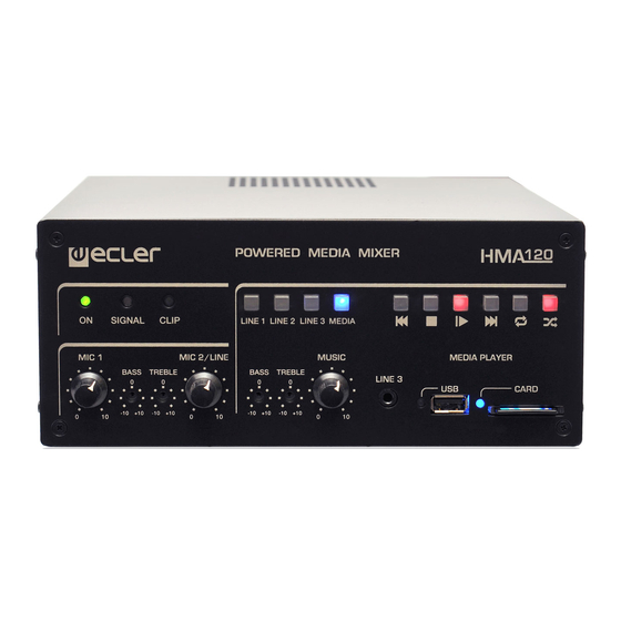
DIAGRAMS and FUNCTION LIST 10.1. Device Front Panel 1 Operating LED indicator, ON 13 Random play key, RANDOM 2 Input signal presence 14 Connector for SD/SDHC indicator light, SP memory cards 3 Signal clipping LED indicator, 15 SD/SDHC memory card LED CLIP indicator 4 Line input selector, LINE1... -
Page 15: Device Rear Panel
10.2. Device Rear Panel 26 Power switch, ON/OFF 34 Input sensitivity adjustment, ADJ 27 Mains socket 35 Micro input, MIC1 28 Fuse holder 36 Input sensitivity adjustment, ADJ 29 Amplified high impedance output 37 Micro/Line input, MIC2 / (LINE) 70V/100V 38 Auxiliary output, AUX 30 Amplified low impedance output 39 RJ-45 connector, REMOTE... -
Page 16: Configuration Diagram
CONFIGURATION DIAGRAM JUMPERS FACTORY ADJUST Phantom: Mic/Line Selector Autoplay Phantom Mic/Line Phantom Mic/Line MIC2 MIC1 off on line Autoplay Auto play... -
Page 17: Block Diagram
BLOCK DIAGRAM... -
Page 18: Technical Characteristics
TECHNICAL CHARACTERISTICS HMA120 Power output (4Ω, 8Ω, 70V & 100V steps) @ 1% THD 110 WRMS @ 4Ω 84 WRMS @ 8Ω 110 WRMS @ 70V @ 41Ω 110 WRMS @ 100V @ 85Ω PEAK 140 WRMS @ 4Ω 105 WRMS @ 8Ω... - Page 19 Mute Configuration Normally open Indicators Signal Present (Trigger level) -35 dB Clip Powers On Auto Standby (Trigger time) after 2 minutes without input signal Supply Mains voltage 115V/230V. Voltage changed internally (NOT BY SWITCH) Power consumption pink noise, 1/8 power @ 4ohm 43 VA / 29W pink noise, 1/3 power @ 4ohm 90 VA / 65W...
- Page 20 NEEC AUDIO BARCELONA S.L. reserves the right to make changes or improvements in the design or manufacturing that may affect these product specifications. For technical queries contact your supplier, distributor or complete the contact form on our website, Support / Technical requests. Motors, 166‐168 08038 Barcelona ‐ Spain ‐ (+34) 932238403 | information@ecler.com www.ecler.com...
Need help?
Do you have a question about the HMA120 and is the answer not in the manual?
Questions and answers