Table of Contents
Advertisement
Advertisement
Table of Contents

Related Manuals for Ecler LPA6000


Summary of Contents for Ecler LPA6000
- Page 1 USER MANUAL MANUAL DE INSTRUCCIONES NOTICE D’EMPLOI BEDIENUNGSANLEITUNG...
-
Page 3: Table Of Contents
6.1. Connection diagram 6.2. Technical characteristics 6.3. Block diagram 6.4. Function list 6.5. Function diagram All numbers subject to variation due to production tolerances. ECLER S.A. reserves the right to make changes or improvements in manufacturing or design which may affect specifications. -
Page 4: Important Note
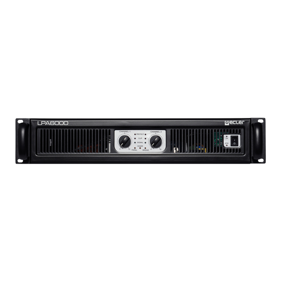
There are no user or serviceable parts inside the amplifier. 2. INTRODUCTION The LPA range of amplifiers offers the classical and acknowledged professional reliability of Ecler amplifiers with a new aesthetic style and at an affordable price. The range consists of 3 stereo models of 320, 500 and 760W RMS per channel over 4Ω. -
Page 5: Installation
3. INSTALLATION 3.1. Placement, mounting, cooling All LPA amplifier models are presented in standard 19” rack format and are 2 units high. It is important that the amplifier, as a heat source, is not placed next to other equipment nor exposed to high temperatures. -
Page 6: Limiter Circuit
The LED indicator “XOVER” on the front panel lights up when this function is activated via the switch on the rear panel (15). 3.5. Limiter circuit This provides additional protection and is always activated on amplifiers in the LPA series. This “ANTICLIP” circuit constantly analyzes the harmonic distortion produced by the excessive clipping of the signal in the amplifier output, and reduces the input level automatically to keep the level of distortion below 0.5% approximately. -
Page 7: Indicators
CAUTION: If these indicators remain permanently switched on, even when all signal input and output cables have been disconnected from the amplifier, this could be a sign of a malfunction which should be analyzed by the official Ecler technical support service. •... -
Page 8: Diagrams
6. DIAGRAMS 6. DIAGRAMAS 6. SCHÉMAS 6. DIAGRAMME 6.1. Connection diagram 6.1. Diagrama de conexión 6.1. Schéma de connexion 6.1. Anschlußdiagramm... -
Page 9: Technical Characteristics
6.2. Technical characteristics 6.2. Características técnicas 6.2. Caractéristiques techniques 6.2. Technische daten LPA6000 LPA10000 LPA16000 POWER 20-20kHz 1% THD 320 WRMS 500 WRMS 760 WRMS 4Ω S tereo 210 WRMS 330 WRMS 450 WRMS 8Ω Stereo 640 WRMS 1000 WRMS 1520 WRMS 8Ω... -
Page 10: Block Diagram
6.3. Block diagram 6.3. Diagrama de bloques 6.3. Blocs de diagrammes 6.3. Blockschatbild... -
Page 11: Function List
6.4. Function list 6.4. Lista de funciones 1. Input attenuator 1. Atenuador de entrada 2. Protection indicator, PROTECT 2. Indicador de funcionamiento de protecciones, PROTECT 3. Clip indicator, CLIP 3. Indicador de recorte, CLIP 4. Signal present indicator, SIGNAL 4. Indicador de presencia de señal en la entrada, SIGNAL 5. -
Page 12: Function Diagram
6.5. Function diagram 6.5. Diagrama de funciones 6.5. Schéma de fonctionnement 6.5. Funktionsübersicht... - Page 13 ECLER Laboratorio de electro-acústica S.A. Motors 166-168, 08038 Barcelona, Spain INTERNET http://www.ecler.com E-mail: info@ecler.es 50.0228.01.00...