Table of Contents
Advertisement
Quick Links
Advertisement
Table of Contents

Subscribe to Our Youtube Channel
Summary of Contents for Ecler HSA2-400ES
- Page 1 HSA2-400ES AMPLIFIER High Impedance Stereo Amplifier USER MANUAL...
-
Page 2: Table Of Contents
INDEX IMPORTANT REMARK ......................3 IMPORTANT SAFETY INSTRUCTIONS ................3 IMPORTANT NOTE ........................ 5 INTRODUCTION ........................5 4.1. Main features ..........................5 INSTALLATION ........................6 5.1. Placement, mounting, cooling ....................6 5.2. Mains connection ........................6 5.3. Input signal connections ......................7 5.4. -
Page 3: Important Remark
1. IMPORTANT REMARK The lightning flash with arrowhead symbol, within an equilateral triangle, is intended to alert the user to the presence of uninsulated “dangerous voltage” within the product’s enclosure that may be of sufficient magnitude to constitute a risk of electric shock to persons. The exclamation point within an equilateral triangle is intended to alert the user to the presence of important operating and maintenance (servicing) instructions in the literature accompanying the appliance. - Page 4 8. Do not install near any heat sources such as radiators, heat registers, stoves, or other apparatus (including amplifiers) that produce heat. 9. Do not defeat the safety purpose of the polarized or grounding type plug. A polarized plug has two blades with one wider than the other. A grounding type plug has two blades and a third grounding prong.
-
Page 5: Important Note
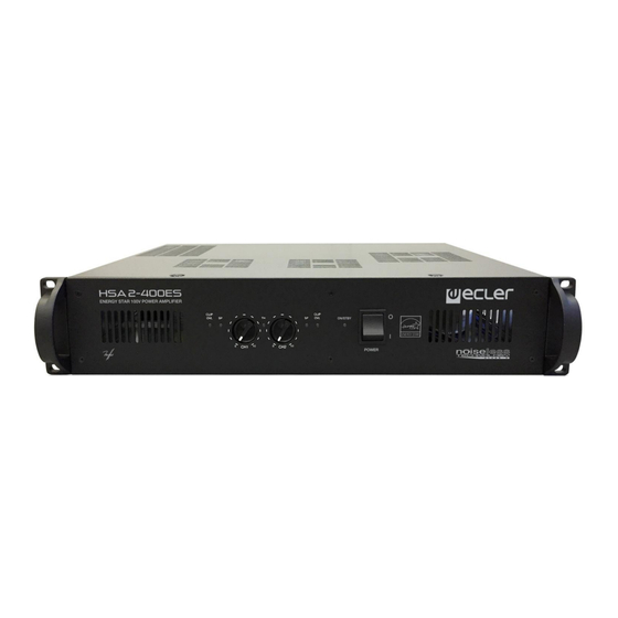
Ecler HSA2-400ES comes with a 3-year warranty. 4. INTRODUCTION The HSA2-400ES is a stereo amplifier with both high and low impedance outputs, offering the proven professional reliability of Ecler amplifiers at an affordable price. It uses very high-performance technology, auto standby and convection cooling, with height of 2 rack units. -
Page 6: Installation
Switchable operation at low impedance (8/4Ω) and high impedance (70/100 V, for speakers with high-impedance transformer) Accepts 8, or 4Ω loads (1 or 2 speakers (8Ω) in parallel) when operating at low impedance 5. INSTALLATION 5.1. Placement, mounting, cooling All HSA amplifier models are presented in standard 19”... -
Page 7: Input Signal Connections
5.3. Input signal connections The signal input connectors are of XLR-3 and EUROBLOCK (15, 16, 17, 18) and electronically balanced. The pin assignment is as follows: XLR-3 EUROBLOCK Hot or direct signal > Pin 2 Cold or phase inverted signal >... -
Page 8: Energy Saving Mode
5.5. Energy saving mode With the Auto Standby mode (switch) enabled, the amplifier activates the automatic circuit, switching to energy saving / low consumption mode when an absence of audio signal is detected at the inputs of the unit. This process occurs in a period of time ≤ to 120 seconds, automatically recovering the normal working regime when the signal reappears. -
Page 9: Output Connections
5.7. Output connections The output section on the rear panel features Euroblock connectors. In STEREO mode, each channel takes the signal from its corresponding input (OUTPUT CH1 from INPUT CH1 and OUTPUT CH2 from INPUT CH2). In MONO/BRIDGE mode, the signal is taken from INPUT CH1 only. If you need to operate the amplifier in BRIDGED mode, you should place the “ST/MONO”... -
Page 10: Operation And Usage
Once inserted, they cannot be removed with bare fingers, for this purpose, a small screwdriver is needed. 6.3. Indicators HSA2-400ES amplifiers include a simple yet effective indication system. CLIP/STBY indicators show the absence of loudspeaker output signal. These indicators may light up for following reasons: 1. -
Page 11: Cleaning
In any case, should these indicators light permanently, this is a sign of malfunction and the causes should be investigated. The CLIP/STBY indicators light up just before the actual clipping threshold at the loudspeaker output is reached. The clip detection circuit considers supply voltage oscillations, so that a dependable clip reading is achieved, even when operating with unstable mains voltage. -
Page 12: Function Diagram
8. FUNCTION DIAGRAM 9. FUNCTION LIST 1. CLIP/STBY indicator CH 1 2. SIGNAL PRESENT indicator CH 1 3. Input attenuator CH 1 4. SIGNAL PRESENT indicator CH 2 5. CLIP/STBY indicator CH 2 6. Input attenuator CH 2 7. THERMAL protection indication 8. -
Page 13: Technical Characteristics
10. TECHNICAL CHARACTERISTICS HSA2-400ES POWER @ 1KHz 1% THD 100V output 1 Channel @ 25 450 WRMS All Channels @ 25 400 WRMS Low Z output: 1 Channel @ 4 390 WRMS 1 Channel @ 8 280 WRMS All Channels @ 4... -
Page 14: Block Diagram
11. BLOCK DIAGRAM... -
Page 15: Configuration Diagram
12. CONFIGURATION DIAGRAM... - Page 16 NEEC AUDIO BARCELONA S.L. reserves the right to make changes or improvements in the design or manufacturing that may affect these product specifications. Motors, 166‐168 08038 Barcelona ‐ Spain ‐ (+34) 932238403 | information@ecler.com www.ecler.com...


Need help?
Do you have a question about the HSA2-400ES and is the answer not in the manual?
Questions and answers