Advertisement
Available languages
Available languages
Quick Links
Advertisement

Related Manuals for TMC Reef Pump Compact 500


Summary of Contents for TMC Reef Pump Compact 500
-
Page 1: Table Of Contents
Reef Pump Compact ALL MODELS Instructions Instruções Instrucciones Anweisungen 26 Instructies Istruzioni Instructions... - Page 2 Model 1500 2500 5000 10000 Modelo/ Modelo/Modell/Model-/Modello/ Modèle Code 1385 1387 1389 1392 1395 Flow rate 500l/h 1500l/h 2500l/h 5000l/h 10000l/h Taxa de fluxo/Tasa de flujo / Fließrate/Stroom/Portata/ Débit Max. power 110W Potência máx./Potencia Max./Max. Leistung/Max. Kracht/Potenza min./Puissance Max. Voltage Voltagem/ Voltaje/Spannung/Spanning/Voltaggio/ Tension PSU Voltage 100-240V 50/60Hz...
-
Page 5: Instructions
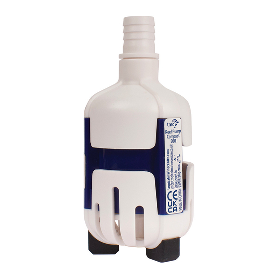
INSTRUCTIONS FOR INSTALLATION AND USE Important Safety Information - Please Read Carefully Caution: Do not use any power supply other than the one supplied with your genuine Reef Pump Compact. The use of a different power supply will invalidate the guarantee. Caution: The Reef Pump Compact controller is not waterproof and therefore must not be mounted above the aquarium or sump, or in any position where it may accidentally fall into water or be splashed by water. - Page 6 PARTS LIST Reef Pump Compact 500 and 1500 Pump strainer/Pump base Pump inlet Pump outlet Pump cover Pump impeller Pump body Reef Pump Compact Pump feet 2500, 5000 and 10000 Power supply unit (PSU) Hosetails Controller Locknut...
- Page 7 INSTALLATION 1. Install the feet in the holes on the underside of the pump body and attach a hosetail as required. 2. Install and secure the Reef Pump Compact controller in a suitable location where it can be easily accessed and adjusted e.g. on the side or back of your aquarium cabinet, but ensuring it is NOT mounted above the aquarium or sump, or in any position where it may accidentally fall into water or be splashed by water.
- Page 8 OPERATION OF THE DC CONTROLLER : 500 and 1500 LEVEL DISPLAY 01: Min. power 10: Max. power CONSTANT STREAM MODE FEED MODE Variable Speed Control With 10 different speed settings to allow precise adjustment of water flow and optimum performance. When the Reef Pump Compact is switched on, the LCD screen on the controller will display To increase the speed of the pump press the INTENSITY button until you reach the required level (maximum level will be displayed on the LCD screen as...
- Page 9 Troubleshooting LED Error Codes E1: Software protection active • Check motor & check controller E2: Hardware protection active • Check motor & check controller E4: Under voltage detected • Check PSU E5: Over voltage detected • Check PSU E6: Open circuit protection active • Check all connection cables and powercord to ensure all are undamaged and connections are correct • If the above are ok, check the motor E7: Impeller is jammed or broken or pump is operating dry •...
- Page 10 Troubleshooting LED Error Codes LED 1 and 2 are flashing: Hardware protection active • Check motor & check controller LED 1 and 4 are flashing: Over voltage detected • Check PSU LED 1 and 5 are flashing: Under voltage detected • Check PSU LED 2 and 3 are flashing: Software protection active •...
- Page 11 2. The impeller should be regularly checked for signs of degradation and replaced as necessary. NOTE: The impeller is not covered under the guarantee. 3. Impellers and a range of other spare parts are available from your local TMC stockist. TROUBLE-SHOOTING If the pump fails to operate: •...
-
Page 12: Instruções
INSTRUÇÕES DE INSTALAÇÃO E USO Informações importantes de segurança - Leia com atenção Cuidado: Não use nenhuma fonte de alimentação diferente da fornecida com a sua Reef Pump Compact original. O uso de uma fonte de alimentação diferente anulará a garantia. Cuidado: O controlador da Reef Pump Compact não é... - Page 13 Reef Pump Compact LISTA DE PEÇAS 500 a 1500 Filtro da bomba Entrada da bomba Saída da bomba Tampa da bomba Rotor da bomba Reef Pump Compact Corpo da bomba 2500, 5000 a 10000 Pés da bomba Fonte de alimentação (PSU) Conectores de mangueira Controlador Contraporca...
- Page 14 INSTALAÇÃO 1. Instale os pés nos orifícios da parte inferior do corpo da bomba e prenda uma mangueira conforme o necessário. 2. Instale e prenda o controlador da Reef Pump Compact num local adequado onde possa ter um fácil acesso e ajustado, por exemplo, na lateral ou traseira do móvel do aquário, mas garantindo que NÃO esteja montado acima do aquário ou reservatório, ou em qualquer posição onde possa acidentalmente cair ou ser molhado com água.
- Page 15 FUNCIONAMENTO DO CONTROLADOR DC : 500 e 1500 MOSTRADOR DE INTENSIDADE 01: Potência mínima 10: Potência máxima MODO DE TRANSMISSÃO CONSTANTE MODO ALIMENTAÇÃO Controlo de variação de velocidade Com 10 configurações de velocidade diferentes para permitir o ajuste preciso do fluxo da água e um desempenho ideal. Quando a Reef Pump Compact é...
- Page 16 Resolução de problemas de códigos de erro de LED E1: Proteção de software ativa • Verifique o motor e o controlador E2: Proteção de hardware ativa • Verifique o motor e o controlador E4: Subtensão detetada • Verifique PSU E5: Sobretensão detetada • Verifique PSU E6: Proteção de circuito aberto ativa •...
- Page 17 Resolução de problemas de códigos de erro de LED LEDs 1 e 2 piscam: proteção de hardware ativa • Verifique o motor e o controlador LEDs 1 e 4 piscam: sobretensão detetada • Verifique PSU LEDs 1 e 5 piscam: Subtensão detetada • Verifique PSU LEDs 2 e 3 piscam: proteção de software ativa •...
- Page 18 2. O rotor deve ser verificado regularmente quando há sinais de degradação e substituído conforme necessário. NOTA: O rotor não está coberto pela garantia. 3. Rotores e uma variedade de outras peças de reposição estão disponíveis na sua loja TMC mais próxima. SOLUÇÃO DE PROBLEMAS Se a bomba não funcionar:...
-
Page 19: Instrucciones
INSTRUCCIONES DE INSTALACIÓN Y USO Información de seguridad importante: Lea atentamente Precaución: No utilice ninguna fuente de alimentación que no sea la suministrada con su Reef Pump Compact original. El uso de una fuente de alimentación diferente anulará la garantía. Precaución: El controlador de la Reef Pump Compact no es resistente al agua y, por lo tanto, no debe montarse sobre el acuario o el sumidero, ni en ninguna posición en la que pueda caer accidentalmente o ser golpeado por el agua. - Page 20 Reef Pump Compact LISTA DE PIEZAS 500 y 1500 Filtro de la bomba Entrada de la bomba Salida de la bomba Tapa de la bomba Rotor de la bomba Reef Pump Compact Cuerpo de la bomba 2500, 5000 y 10000 Pies de la bomba Fuente de alimentación (PSU) Conectores de manguera...
- Page 21 INSTALACIÓN 1. Instale los pies en los orificios en la parte inferior del cuerpo de la bomba y conecte una manguera según sea necesario. 2. Instale y asegure que el controlador de la Reef Pump Compact en un lugar adecuado donde se pueda acceder y ajustar fácilmente, por ejemplo, en el costado o en la parte posterior de lo mueble del acuario, pero asegurándose de que NO esté...
- Page 22 FUNCIONAMIENTO DEL CONTROLADOR DC : 500 e 1500 PANTALLA DE INTENSIDAD 01: Potencia mínima 10: Potencia máxima MODO DE TRANSMISIÓN CONSTANTE MODO ALIMENTACIÓN Control de variación de velocidad Con 10 configuraciones de velocidad diferentes para permitir un ajuste preciso del flujo de agua y un rendimiento óptimo. Cuando se enciende la Reef Pump Compact, la pantalla LCD del controlador muestra...
- Page 23 Solución de problemas de códigos de error de LED E1: protección de software activa • Revise el motor y revise el controlador E2: protección de hardware activa • Revise el motor y revise el controlador E4: se detectó subtensión • Verificar PSU E5: se detectó...
- Page 24 Solución de problemas de códigos de error de LED LED 1 y 2 parpadean: protección de hardware activa • Revise el motor y revise el controlador LED 1 y 4 parpadean: se detectó sobretensión • Verificar PSU LED 1 y 5 parpadean: se detectó subtensión • Verificar PSU LED 2 y 3 parpadean: protección de software activa •...
- Page 25 NOTA: El eje del rotor de la bomba no se puede quitar. 2. Los rotores y una variedad de otras piezas de repuesto están disponibles en su tienda TMC más cercana. 3. NOTA: El rotor no está cubierto por la garantía.
-
Page 26: Anweisungen
ANWEISUNGEN FÜR INSTALLATION UND GEBRAUCH Wichtige Sicherheitsinformationen - Bitte sorgfältig lesen Achtung: Verwenden Sie kein anderes Netzteil als das mit Ihrer Original Reef Pump Compact gelieferte. Bei Verwendung eines anderen Netzteils ungültig sich die Garantie. Achtung: Der Reef Pump Compact Controller ist nicht wasserdicht und darf daher nicht über dem Aquarium oder Sumpf oder an einer Stelle montiert werden, an der er versehentlich ins Wasser fallen oder mit Wasser bespritzt werden könnte. - Page 27 Reef Pump Compact 500 und 1500 EINZELTEILE Pumpensieb Pumpeneingang Pumpenausgang Pumpendeckel Pumpenlaufrad Reef Pump Compact Pumpenkörper 2500, 5000 und 10000 Pumpen Füße Netzteil (PSU) Schlauchadapter Controller Kontermutter...
- Page 28 ANSCHLUSS 1. Installieren Sie die Füße in den Löchern an der Unterseite des Pumpenkörpers und befestigen Sie nach Bedarf einen Schlauchadapter. 2. Installieren und sichern Sie den Reef Pump Contact Controller an einem geeigneten Ort, an dem er leicht zugänglich und einstellbar ist, z. an der Seite oder Rückseite Ihres Aquarienschranks, aber stellen Sie sicher, dass es NICHT über dem Aquarium oder Sumpf oder an einer Stelle montiert wird, an der es versehentlich ins Wasser fallen oder mit Wasser bespritzt werden kann.
- Page 29 BETRIEB DES DC-CONTROLLERS : 500 und 1500 LEVEL-ANZEIGE 01: mind. Energie 10: max. Energie KONSTANT-STREAM-MODUS ZUFUHRMODUS Variable Geschwindigkeitsregelung Mit 10 verschiedenen Geschwindigkeitseinstellungen für eine präzise Einstellung des Wasserflusses und optimale Leistung. Wenn die Reef Pump Compact eingeschaltet ist, wird der der LCD-Bildschirm des Controllers gezeigt. Um die Geschwindigkeit der Pumpe zu erhöhen, drücken Sie die INTENSITY-Taste, bis Sie die gewünschte Stufe erreicht haben (maximale Stufe wird auf dem LCD-Bildschirm angezeigt als Um die Intensität zu verringern, halten Sie die Intensitätstaste gedrückt, um die gewünschte Geschwindigkeit zu erreichen.
- Page 30 Fehlerbehebung bei LED-Fehlercodes E1: Softwareschutz akti • Motor prüfen und Steuerung prüfen E2: Hardwareschutz akti • Motor prüfen & Steuerung prüfen E4: Unterspannung erkann • Netzteil prüfen E5: Überspannung erkann • Netzteil prüfen E6: Drahtbruch Schutz akti • Überprüfen Sie alle Verbindungskabel und Netzkabel, um sicherzustellen, dass alle unbeschädigt sind und alle Verbindungen korrekt sind •...
- Page 31 Fehlerbehebung bei LED-Fehlercodes LED 1 und 2 blinken: Hardwareschutz akti • Motor prüfen & Steuerung prüfen LED 1 und 4 blinken: Überspannung erkann • Netzteil prüfen LED 1 und 5 blinken: Unterspannung erkann • Netzteil prüfen LED 2 und 3 blinken: Softwareschutz akti • Motor prüfen und Steuerung prüfen LED 3 und 4 blinken: Drahtbruch Schutz akti •...
- Page 32 2. Das Laufrad sollte regelmäßig auf Anzeichen von Verschleiß überprüft und bei Bedarf ersetzt werden. HINWEIS: Das Laufrad fällt nicht unter die Garantie. 3. Laufräder und eine Reihe anderer Ersatzteile sind bei Ihrem örtlichen TMC-Händler erhältlich. FEHLERBEHEBUNG Wenn die Pumpe nicht funktioniert: •...
-
Page 33: Instructies
INSTRUCTIES VOOR INSTALLATIE EN GEBRUIK Belangrijke veiligheidsinformatie - lees deze zorgvuldig Waarschuwing: Gebruik alleen de voedingseenheid die wordt meegeleverd met uw originele Reef Pump Compact. Bij het gebruik van een andere voedingseenheid verliest de garantie zijn geldigheid. Waarschuwing: De Reef Pump Compact-controller is niet waterdicht en mag daarom niet worden geïnstalleerd boven het aquarium of de pompbak of op een andere plaats waar deze per ongeluk in het water kan vallen of geraakt kan worden door spetters van (aquarium) water. - Page 34 Reef Pump Compact 500 en 1500 LIJST VAN ONDERDELEN Pompzeef Pompinlaat Pompuitlaat Pompafdekking Pomprotor Reef Pump Compact 2500, 5000 en 10000 Pomplichaam Pomp voeten Voedingseenheid (PSU) Slanguiteinden Controller Borgmoer...
- Page 35 INSTALLATIE 1. Installeer de poten in de gaten aan de onderkant van het pomplichaam en bevestig een slanguiteinde van het slanguiteinde zoals aangegeven. 2. Installeer en bevestig de controller voor de Reef Pump Compact op een geschikte plaats waar deze gemakkelijk te bereiken is en afgesteld kan worden, bijvoorbeeld aan de zijkant of achterkant van uw aquariumkast.
- Page 36 WERKING VAN DE GELIJKSTROOMCONTROLLER : 500 en 1500 SCHERM 01: Min. vermogen 10: Max. vermogen CONSTANTE STREAMMODUS VOEDINGSMODUS Toerentalregeling Met 10 verschillende toerentallen kunt u het debiet en de prestatie van de pomp nauwkeurig afstellen. Wanneer de Reef Pump Compact is switched on, wordt ingeschakeld, wordt op het LCD-scherm van de controller weergegeven U kunt het toerental van de pomp verhogen door op INTENSITY te drukken totdat u de gewenste waarde bereikt (maximumwaarde wordt weergegeven op het LCD-scherm als Om te verlagen, blijf op de intensiteitsknop drukken om de gewenste snelheid te bereiken.
- Page 37 Problemen met LED-foutcodes oplossen E1: Softwarebeveiliging actief • Controleer motor & controleer controller E2: Hardware beveiliging actief • Controleer motor & controleer controller E4: Onderspanning gedetecteerd • Controleer PSU E5: Overspanning gedetecteerd • Controleer PSU E6: Open circuit beveiliging actief • Controleer alle aansluitkabels en netsnoer om er zeker van te zijn dat ze allemaal onbeschadigd zijn en dat de aansluitingen correct zijn •...
- Page 38 Problemen met LED-foutcodes oplossen LED 1 en 2 knipperen: Hardware beveiliging actief • Controleer motor & controleer controller LED 1 en 4 knipperen: Overspanning gedetecteerd • Controleer PSU LED 1 en 5 knipperen: Onderspanning gedetecteerd • Controleer PSU LED 2 en 3 knipperen: Softwarebeveiliging actief • Controleer motor & controleer controller LED 3 en 4 knipperen: Open circuit beveiliging actief •...
- Page 39 2. De rotor moet regelmatig worden gecontroleerd op tekenen van slijtage en zo nodig vervangen worden. Opmerking: De rotor valt niet onder de garantie. 3. Rotors, en andere reserveonderdelen zijn verkrijgbaar bij uw plaatselijke TMC leverancier. PROBLEMEN OPLOSSEN Als de pomp niet werkt: •...
-
Page 40: Istruzioni
ISTRUZIONI PER L'INSTALLAZIONE E L'USO Informazioni importanti per la sicurezza - Leggere attentamente Attenzione: Non utilizzare un alimentatore elettrico diverso da quello fornito con la pompa Reef Pump Compact originale. L’uso di un alimentatore elettrico diverso renderà nulla la garanzia. Attenzione: L’unità... - Page 41 Reef Pump Compact 500 e 1500 ELENCO COMPONENTI Filtro Aspirazione pompa Mandata pompa Calotta Girante Reef Pump Compact Corpo pompa 2500, 5000 e 10000 Piedini Alimentatore elettrico (PSU) Raccordo per tubo di gomma Unità di controllo Dado di sicurezza...
- Page 42 INSTALLAZIONE 1. Montare i piedini nei fori sul lato inferiore del corpo della pompa e fissare il raccordo per tubo di gomma. 2. Montare e fissare l’unità di controllo della pompa Reef Pump Compact in un sede idonea che permetta di accedervi e regolarla facilmente, per esempio sul fianco o sul retro dell’armadio dell’acquario, ma assicurandosi che NON risulti montata al di sopra dell’acquario o della vasca di stoccaggio, né...
- Page 43 FUNZIONAMENTO DELL’UNITÀ DI CONTROLLO IN CORRENTE CONTINUA 500 e 1500 SCHERM 01: Min. vermogen 10: Max. vermogen MODALITÁ FLUSSO COSTANTE MODALITÁ ALIMENTAZIONE Controllo a velocità variabile Con 10 impostazioni di velocità diverse per consentire una regolazione precisa del flusso idrico e prestazioni ottimali.
- Page 44 Risoluzione dei problemi relativi ai LED E1: Software protection active • Controllare motore e unità di controllo E2: Protezione hardware attiva • Controllare motore e unità di controllo E4: Under voltage detected • Controllare alimentatore elettrico E5: Over voltage detected • Controllare alimentatore elettrico E6: Protezione del circuito elettrico aperto attiva •...
- Page 45 Risoluzione dei problemi relativi ai LED LED 1 e 2 lampeggiano: protezione hardware attiva • Controllare motore e unità di controllo LED 1 e 4 lampeggiano: Over voltage detected • Controllare alimentatore elettrico LED 1 e 5 lampeggiano: Under voltage detected • Controllare alimentatore elettrico LED 2 e 3 lampeggiano: Software protection active •...
- Page 46 2. La girante deve essere controllata periodicamente per individuarne eventuali segni di usura e, se necessario, sostituita. Nota: La girante è esclusa dalla garanzia. 3. Le giranti e un assortimento di altre parti di ricambio sono disponibili presso il vostro distributore TMC di zona. RISOLUZIONE DEI PROBLEMI Se la pompa non funziona: •...
-
Page 47: Instructions
INSTRUCTIONS D'INSTALLATION ET D'UTILISATION Informations de sécurité importantes - Veuillez lire attentivement Attention: N'utilisez pas d'alimentation autre que celle fournie avec votre Reef Pump Compact d'origine. L'utilisation d'une alimentation différente annulera la garantie. Attention: le contrôleur de la Reef Pump Compact n'est pas étanche et ne doit donc pas être monté au-dessus de l'aquarium ou du réservoir, ou dans une position où... - Page 48 Reef Pump Compact 500 et 1500 LISTE DES PIÈCES Crépine de pompe Entrée de la pompe Sortie de pompe Couvercle de pompe Rotor de pompe Reef Pump Compact 2500, 5000 et 10000 Corps de pompe Pieds de pompe Alimentation (PSU) Connecteurs de tuyau Unité...
- Page 49 INSTALLATION 1. Installez les pieds dans les trous au bas du corps de la pompe et fixez un connecteur de tuyau au besoin. 2. Installez et fixez le contrôleur de la Reef Pump Compact (modèle à débit variable uniquement) dans un endroit approprié où il peut être facilement accessible et ajusté, par exemple sur le côté...
- Page 50 FONCTIONNEMENT DU CONTRÔLEUR DC : 500 et 1500 ÉCRAN D'AFFICHAGE DE L'INTENSITÉ 01: Puissance minimale 10: Puissance maximale MODE DE TRANSMISSION CONSTANTE MODE D'ALIMENTATION Contrôle de variation de vitesse Avec 10 réglages de vitesse différents pour permettre un réglage précis du débit d'eau et des performances optimales.
- Page 51 Dépannage des codes d'erreur LED E1: Protection logicielle active • Vérifier le moteur et vérifier le contrôleur E2: protection matérielle active • Vérifier le moteur et le contrôleur E4: Sous-tension détectée • Vérifiez PSU E5: surtension détectée • Vérifier PSU E6: protection contre les circuits ouverts active •...
- Page 52 Dépannage des codes d'erreur LED Les LED 1 et 2 clignotent: protection matérielle active • Vérifier le moteur et le contrôleur Les LED 1 et 4 clignotent: surtension détectée • Vérifier PSU Les LED 1 et 5 clignotent: Sous-tension détectée • Vérifiez PSU Les LED 2 et 3 clignotent: Protection logicielle active •...
- Page 53 2. Le rotor doit être vérifié régulièrement pour détecter tout signe de dégradation et remplacé si nécessaire. REMARQUE: Le rotor n'est pas couvert par la garantie. 3. Les rotors et une variété d'autres pièces de rechange sont disponibles dans votre magasin TMC le plus proche RÉSOLUTION DES PROBLÈMES Si la pompe ne fonctionne pas: •...
- Page 56 tropicalmarinecentre.com info@tropicalmarinecentre.co.uk Iberia Solesbridge Lane Rua Cidade de Paris 6 Chorleywood Parque Industrial do Arneiro Hertfordshire WD3 5SX 2660-456 São Julião do Tojal England Portugal Call +351 (0) 219 739 140 Call +44 (0) 1923 284151...
Need help?
Do you have a question about the Reef Pump Compact 500 and is the answer not in the manual?
Questions and answers